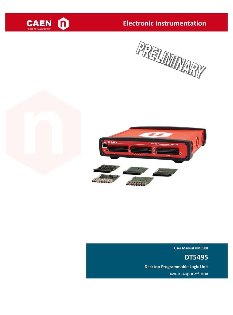
Caen V2495 User manual

CAEN
Tools for Discovery
n
Electronic Instrumentation
User Manual UM5175
V2495/VX2495
VME Programmable Logic Unit
Rev. 1 - October 11th, 2018

Purpose of this Manual
This document contains the full hardware and software description of the V2495/VX2495 VME Programmable Logic
Unit.
Change Document Record
Date
Revision
Changes
August 01st, 2016
00
Initial release
October 11th, 2018
01
Removed “Coming Soon” from the User Firmware FW2495SC in Tab.
1.2. Corrected caption in Fig. 10.1. Removed Subsect. “CAENComm
Demo” and added Subsect. PLULib Library in Sect. Software Tools.
Updated Sect. Reference Documents, Sect. Flash Configuration
(0x8500-0x8AFF) , Sect. Introduction, Chap. 12.
Symbols, Abbreviated Terms and Notation
AM
Address Modifier
FPGA
Field Programmable Gate Array
GA
Geographical Address
GDG
Gate and Delay Generator
LB
Local Bus
LBM
Local Bus Master
LBS
Local Bus Slave
LED
Light Emitting Diode
MFPGA
Main FPGA
SPI
Serial Peripheral Interface
SW
Switch
UFPGA
User FPGA
USB
Universal Serial Bus
VBA
VME Base Address
VME
Versa Module Europa
Reference Documents
[RD1] GD2512 –CAENUpgrader QuickStart Guide
[RD2] UM3181 –V1495 General Purpose VME Board
[RD3] A967 Adapter for P50E –068S 68 Pin Connectors
[RD4] UM6510 –CAEN PLULib Library User Manual
All documents can be downloaded at: http://www.caen.it/csite/LibrarySearch.jsp

CAEN S.p.A.
Via Vetraia, 11 55049 Viareggio (LU) - ITALY
Tel. +39.0584.388.398 Fax +39.0584.388.959
www.caen.it
© CAEN SpA –2018
Disclaimer
None of the parts of this manual may be reproduced in any form or by any means, electronic, mechanical, recording, or
otherwise, without the prior written permission of CAEN SpA.
The information contained herein has been carefully checked and is believed to be accurate; however, no responsibility
is assumed for inaccuracies. CAEN SpA reserves the right to modify its products specifications without giving any
notice; for up to date information please visit www.caen.it.
MADE IN ITALY: We stress the fact that all the boards are made in Italy because in this globalized world, where getting
the lowest possible price for products sometimes translates into poor pay and working conditions for the people who
make them, at least you know that who made your board was reasonably paid and worked in a safe environment. (this
obviously applies only to the boards marked "MADE IN ITALY", we cannot attest to the manufacturing process of "third
party" boards).

CAEN
Electronic Instrumentation
UM5175 –V2495/VX2495 User Manual rev. 1
4
Index
Purpose of this Manual .........................................................................................................................................2
Change Document Record...................................................................................................................................2
Symbols, Abbreviated Terms and Notation ....................................................................................................... 2
Reference Documents...........................................................................................................................................2
Index ........................................................................................................................................4
List of Figures.........................................................................................................................5
List of Tables..........................................................................................................................6
Safety Notices.........................................................................................................................7
1Introduction.....................................................................................................................8
2Block Diagram ..............................................................................................................10
3Main Components and Interconnections..................................................................11
3.1 USB Interface............................................................................................................................................12
3.2 VME Interface........................................................................................................................................... 12
3.3 Main FPGA................................................................................................................................................12
3.4 User FPGA................................................................................................................................................12
3.5 Gate and Delay Generator......................................................................................................................12
3.6 Clock Distribution .....................................................................................................................................12
4Front Panel Connectors, LEDs and Labels ..............................................................13
5Internal Connectors and LEDs...................................................................................16
6Technical Specifications.............................................................................................19
7Getting Started with V2495 .........................................................................................21
7.1 Shipping Content......................................................................................................................................21
7.2 Mezzanine Boards Installation ............................................................................................................... 22
7.3 Front Panel Connector Cabling.............................................................................................................. 23
7.4 Setting the VME Base Address..............................................................................................................24
7.5 Selecting the User FPGA Firmware......................................................................................................24
7.6 Power-on Configuration Sequence........................................................................................................25
Boot Mode Selection......................................................................................................................................................25
8Driver and Software Installation.................................................................................26
8.1 Drivers........................................................................................................................................................26
Direct USB Driver............................................................................................................................................................26
VME Access......................................................................................................................................................................29
8.2 Software Tools..........................................................................................................................................30
CAENUpgrader.................................................................................................................................................................30
PLULib Library.................................................................................................................................................................33
9Communication Interfaces..........................................................................................34
9.1 VME Bus....................................................................................................................................................34
9.2 USB............................................................................................................................................................ 34
9.3 Address Map.............................................................................................................................................35
User FPGA Data Access (0x0000-0x0FFF)................................................................................................................35
User FPGA Register Access (0x1000-0x7FFF).........................................................................................................35
VME Interface Registers (0x8000-0x80FF)................................................................................................................36
VME Control Register.....................................................................................................................................................36
VME Interrupt Level Register .......................................................................................................................................36
VME Interrupt Status ID Register................................................................................................................................36
Scratch Register..............................................................................................................................................................36
VME Base Address Register ........................................................................................................................................36
Configuration ROM (0x8100-0x81FF).........................................................................................................................37
Configuration and Status Registers (0x8200-0x83FF)...........................................................................................38
MFPGA Firmware Revision Register..........................................................................................................................38
Software Reset Register................................................................................................................................................38
Scratch Register..............................................................................................................................................................38
Flash Configuration (0x8500-0x8AFF)........................................................................................................................38
Internal Scratch SRAM(0x8C00-0x8FFF)...................................................................................................................38
10 Firmware Development................................................................................................39

CAEN
Electronic Instrumentation
UM5175 –V2495/VX2495 User Manual rev. 1
5
10.1 Introduction................................................................................................................................................ 39
10.2 User FPGA I/O ports................................................................................................................................40
10.3 Local Bus Interface .................................................................................................................................. 43
10.4 Gate and Delay Controller ......................................................................................................................45
General Description........................................................................................................................................................45
Register Description.......................................................................................................................................................46
Example Procedures......................................................................................................................................................47
10.5 Porting V1495 to V2495..........................................................................................................................48
11 Demo Firmware ............................................................................................................49
11.1 Introduction................................................................................................................................................ 49
11.2 Demo Structure ........................................................................................................................................ 49
11.3 Demo Setup..............................................................................................................................................49
11.4 Gate Pattern Demo Description.............................................................................................................50
Introduction......................................................................................................................................................................50
Register Map ....................................................................................................................................................................50
Register Description.......................................................................................................................................................50
11.5 Pattern Recorder Demo Description ..................................................................................................... 53
Introduction......................................................................................................................................................................53
Register Map ....................................................................................................................................................................53
Register Description.......................................................................................................................................................53
11.6 DAC Demo Description...........................................................................................................................55
Introduction......................................................................................................................................................................55
Register Map ....................................................................................................................................................................55
Register Description.......................................................................................................................................................55
11.7 Gate and Delay Demo Description........................................................................................................ 57
Introduction......................................................................................................................................................................57
Register Map ....................................................................................................................................................................57
Register Description.......................................................................................................................................................57
12 Software Development ................................................................................................60
13 CAEN Support...............................................................................................................61
13.1 Returns and Repairs................................................................................................................................61
13.2 Technical Support Service...................................................................................................................... 61
List of Figures
Fig. 2.1: Block diagram......................................................................................................................................................................10
Fig. 3.1: Main components and interconnections...........................................................................................................................11
Fig. 3.2: The UFPGA and GDG interface........................................................................................................................................12
Fig. 4.1: Front panels view................................................................................................................................................................13
Fig. 5.1: On-board internal connectors and LEDs..........................................................................................................................16
Fig. 7.1: V2495 motherboard with mezzanine boards...................................................................................................................22
Fig. 7.2: Multi-pin connector pin assignment..................................................................................................................................23
Fig. 7.3: CAEN A967 Cable Adapter................................................................................................................................................23
Fig. 7.4: Base Address on-board rotary switches ..........................................................................................................................24
Fig. 7.5: User Firmware rotary switch..............................................................................................................................................24
Fig. 7.6: Boot mode jumper for the Main FPGA.............................................................................................................................25
Fig. 8.1: V2495 hardware detection.................................................................................................................................................26
Fig. 8.2: USB driver manual installation: Step1..............................................................................................................................27
Fig. 8.3: USB driver manual installation: Step2..............................................................................................................................27
Fig. 8.4: USB driver manual installation: Step3..............................................................................................................................28
Fig. 8.5: USB driver manual installation: Step4..............................................................................................................................28
Fig. 8.6: USB driver manual installation: Step5..............................................................................................................................29
Fig. 8.7: CAENUpgrader Get Firmware Release menu................................................................................................................30
Fig. 8.8: CAENUpgrader MFPGA Upgrade Firmware menu........................................................................................................31
Fig. 8.9: CAENUpgrader UFPGA flash memory image menu......................................................................................................32
Fig. 8.10: CAENUpgrader UFPGA Upgrade Firmware menu......................................................................................................32
Fig. 8.11: CAEN PLULib Demo application prompt.......................................................................................................................33
Fig. 10.1: Simplified scheme related to Tab. 10.5..........................................................................................................................41
Fig. 10.2: Local bus signals at a write access (x8BADF00D is written on register x1800) ......................................................43
Fig. 10.3: Local bus signal at a read access (x8BADF00D is read from register x1800).........................................................43
Fig. 10.4: Prefetch mechanism.........................................................................................................................................................44
Fig. 10.5: Gate and Delay parameters representation..................................................................................................................45

CAEN
Electronic Instrumentation
UM5175 –V2495/VX2495 User Manual rev. 1
6
List of Tables
Tab. 1.1: Comparison table between V1495 and V2495 ................................................................................................................8
Tab. 1.2: Table of models and related items.....................................................................................................................................9
Tab. 6.1: V2495/VX2495 specifications table.................................................................................................................................19
Tab. 6.2: A395A Mezzanine specifications table............................................................................................................................19
Tab. 6.3: A395B Mezzanine specifications table............................................................................................................................20
Tab. 6.4: A395C Mezzanine specifications table ...........................................................................................................................20
Tab. 6.5: A395D Mezzanine specifications table ...........................................................................................................................20
Tab. 6.6: A395E Mezzanine specifications table............................................................................................................................20
Tab. 9.1: V2495 register address map ............................................................................................................................................35
Tab. 9.2: VME interface registers.....................................................................................................................................................36
Tab. 9.3: ROM Address Map of the V2495.....................................................................................................................................37
Tab. 9.4: CSR registers .....................................................................................................................................................................38
Tab. 10.1: Clock ports description table..........................................................................................................................................40
Tab. 10.2: Mainboard Robinson-Nugent connector description table.........................................................................................40
Tab. 10.3: LEMO G ports description table.....................................................................................................................................40
Tab. 10.4: Expansion I/O ports description table...........................................................................................................................41
Tab. 10.5: A395D mapping................................................................................................................................................................41
Tab. 10.6: LED ports description table ............................................................................................................................................42
Tab. 10.7: Gate and Delay Generator ports description table......................................................................................................42
Tab. 10.8: Local Bus ports description table...................................................................................................................................42
Tab. 10.9: Main parameters of the Gate and Delay Generator....................................................................................................45
Tab. 10.10: Local Bus registers description for the Gate and Delay Generator configuration ................................................46

CAEN
Electronic Instrumentation
UM5175 –V2495/VX2495 User Manual rev. 1
7
Safety Notices
CAUTION: this product may need proper cooling.
USING V2495 WITH MEZZANINE BOARDS MAY REQUIRE CRATES WITH
FORCED COOLING AIR FLOW SINCE OVERHEATING MAY DAMAGE THE
MODULE (refer to Chap. 6)
CAUTION: this product needs proper handling.
V2495 DOES NOT SUPPORT LIVE INSERTION (HOT SWAP)!
TAKE CARE OF REMOVING OR INSERTING THE BOARD WHEN THE VME
CRATE IS POWERED OFF!
CAEN provides the specific document “Precautions for Handling, Storage and
Installation”, available in the documentation tab of the product’s web page. The user is
required to read this manual before using CAEN equipment.

CAEN
Electronic Instrumentation
UM5175 –V2495/VX2495 User Manual rev. 1
8
1Introduction
The V2495 is a general-purpose programmable FPGA and I/O unit
housed in a 1-unit wide VME 6U module. The board is a suitable
solution for the implementation of digital functions such as
Coincidence, Trigger Logic, Gate and Delay Generator,
Input/Output Register and more.
The programmable architecture is based on the User FPGA
(hereafter UFPGA). The UFPGA is directly interfaced to the front
panel I/Os and to an onboard Gate and Delay Generator, that
allows to delay and gate up to 32 signals. A second FPGA, the
Main FPGA (hereafter MFPGA), is responsible for USB and VME
interface management. The MFPGA communicates with the
UFPGA through an internal local bus.
The presence of three expansion slots interfaced to the UFPGA
allows to extend the channel interface of the V2495 by adding up
to three independent mezzanine boards. Five mezzanine board
types are available: A395A, A395B, A395C, A395D, A395E (see
Tab. 1.2). The V2495 can reach a maximum of 194 I/O channels.
The board can be controlled and programmed through either the
VME or the USB interface. The CAENUpgrader software tool is
provided to upload the FPGA firmware. An onboard dedicated
JTAG connector allows for in-system JTAG configuration and
debugging (e.g. using Altera SignalTap).
The V2495 can be considered as an evolution of CAEN V1495
board with which it bears several analogies (e.g. the front panel
connectors have the same function and nomenclature with
respect to the V1495). In addition, it provides enhanced logic
resources, features and interfaces.
The following Tab. 1.1 is a comparison table between the two
modules.
V1495
V2495
User FPGA
Altera Cyclone EPI1C20, 20k LEs
Altera Cyclone V GX, 50k LEs
Front Panel I/O
Sections A and B (2 x 68-pin Robinson Nugent connector; 32 input channel each)
Section C (1 x 68-pin Robinson Nugent connector; 32 output channels)
Section G (2 X LEMO connector; input/output channels)
On-board Delay
Generator
4 Delay lines
32 Gate and Delay lines
Local Bus
16-bit 50 MHz parallel interface
VME Bus
Addressing spaces: A24, A32
Data transfer modes: D16, D32, BLT32
Geographical addressing (VX2495)
USB Interface
Not Supported
USB2.0
Mezzanine
Boards
A395A, A395B, A395C, A395D, A395E
Tab. 1.1: Comparison table between V1495 and V2495

CAEN
Electronic Instrumentation
UM5175 –V2495/VX2495 User Manual rev. 1
9
Tab. 1.2 lists the board models, the firmware and hardware related products as well as the ordering option
information.
Board Models
Description
Product Code
V2495
VME64 Programmable Logic Unit
WV2495XAAAAA
VX2495
VME64X Programmable Logic Unit
WVX2495XAAAA
User Firmware
Description
Product Code
FW2495SC
Channel Latching Scaler for V2495
WFW2495SCXAA
Related Products
Description
Product Code
A2818
A2818 –PCI Optical Link (Rhos compliant)
WA2818XAAAAA
A3818A
A3818A –PCIe 1 Optical Link
WA3818AXAAAA
A3818B
A3818B –PCIe 2 Optical Link
WA3818BXAAAA
A3818C
A3818C –PCIe 4 Optical Link
WA3818CXAAAA
V1718
V1718 - VME-USB 2.0 Bridge
WV1718XAAAAA
V1718LC
V1718LC - VME-USB 2.0 Bridge (Rohs Compliant)
WV1718LCXAAA
VX1718
VX1718 - VME-USB 2.0 Bridge
WVX1718XAAAA
VX1718LC
VX1718LC - VME-USB 2.0 Bridge (Rohs Compliant)
WV1718LCXAAA
V2718
V2718 - VME-PCI Bridge
WV2718XAAAAA
V2718LC
V2718LC - VME-PCI Bridge (Rohs compliant)
WV2718LCXAAA
VX2718
VX2718 - VME-PCI Bridge
WVX2718XAAAA
VX2718LC
VX2718LC - VME-PCI Bridge
WVX2718LCXAA
V2718LC KIT
V2718KITLC - VME-PCI Bridge (V2718) + PCI Optical Link (A2818) +
Optical Fibre 5m duplex (AY2705) (Rohs)
WK2718LCXAAA
V2718 KIT
V2718KIT - VME-PCI Bridge (V2718) + PCI OpticalLink (A2818) + Optical
Fibre 5m duplex (AY2705)
WK2718XAAAAA
V2718 KIT-B
V2718KITB - VME-PCI Bridge (V2718) + PCIe Optical Link (A3818A) +
Optical Fibre 5m duplex (AY2705)
WK2718XBAAAA
VX2718LC KIT
VX2718KITLC - VME-PCI Bridge (VX2718) + PCI Optical Link (A2818) +
Optical Fibre 5m duplex (AY2705) (Rohs)
WKX2718LCXAA
VX2718 KIT
VX2718KIT - VME-PCI Bridge (VX2718) + PCI OpticalLink (A2818) +
Optical Fibre 5m duplex (AY2705)
WKX2718XAAAA
VX2718 KIT-B
VX2718KITB - VME-PCI Bridge (VX2718) + PCIe Optical Link (A3818A) +
Optical Fibre 5m duplex (AY2705)
WKX2718XBAAA
Accessories
Description
Product Code
A395A
32 LVDS/ECL/PECL input channels
WA395XAAAAAA
A395B
32 LVDS output channels
WA395XBAAAAA
A395C
32 ECL output channels
WA395XCAAAAA
A395D
8 NIM/TTL input/output channels
WA395XDAAAAA
A395E
8 Channel 16Bit ±5V DAC
WA395XEAAAAA
A967
32 Channel Cable Adapter (1x32 to 2x16)
WA967XAAAAAA
Tab. 1.2: Table of models and related items
⁽*⁾ Paid firmware; unlocking license needed. Please, refer to the FW2495SC web page for details.

CAEN
Electronic Instrumentation
UM5175 –V2495/VX2495 User Manual rev. 1
10
2Block Diagram
A
B
C
32
32
32
32
32
32
USER
PROGRAMMABLE
FPGA
(UFPGA)
MAIN FPGA
(MFPGA)
16 bit
VME BUS
LOCAL
BUS
G
Gate and Delay
Generator
D
E
F
USB
32
Fig. 2.1: Block diagram

CAEN
Electronic Instrumentation
UM5175 –V2495/VX2495 User Manual rev. 1
11
3Main Components and Interconnections
User
FPGA
(Cyclone V GX)
Main
FPGA
(Cyclone V E)
Gate and Delay
Generator
Local Bus
(16-bit@50MHz)
USB
PHY
VME BUS (P1/P2)
FLASH
FLASH
FLASH
A PORT (IN) /
D PORT (IN/OUT)
B PORT (IN) /
E PORT (IN/OUT)
C PORT (OUT) /
F PORT (IN/OUT)
USB
G PORT (IN/OUT)
JTAG
JTAG
P1
P2
USER FW
SELECTOR
50 MHz
50 MHz
50 MHz
AD9520
VME BASE ADDRESS
SELECTORS
Fig. 3.1: Main components and interconnections

CAEN
Electronic Instrumentation
UM5175 –V2495/VX2495 User Manual rev. 1
12
3.1 USB Interface
The V2495 is equipped with a USB2.0 interface. The USB physical layer is managed by a high-speed (480 Mb/s)
transceiver controlled by the Main FPGA.
3.2 VME Interface
The P1 and P2 are the standard VME connectors both interfaced with the Main FPGA.
3.3 Main FPGA
The MFPGA (Altera Cyclone V E) manages the VME and USB interfaces and the connection with the UFPGA through a
proprietary 16-bit@50 MHz local bus. The MFPGA has a dedicated external flash memory for configuration purposes. It
also pilots the flash memories dedicated to loading the firmware on the UFPGA and on the GDG.
3.4 User FPGA
The User FPGA (Altera Cyclone V GX) manages the I/O peripherals (A/D, B/E, G, C/F ports) and communicates with the
GDG. A dedicated external flash memory can store a set of firmware images to be loaded on the User FPGA. A
dedicated JTAG connector allows to program the UFPGA “on-the-fly” for fast firmware prototyping and debugging.
3.5 Gate and Delay Generator
The V2495 hosts a Gate and Delay Generator (see Fig. 3.2) able to provide up to 32 gated and delayed signals (“delayed
signals”) triggered by 32 inputs (“start signals”). The gate width and delay value are user programmable. The GDG is an
external component implemented in a Xilinx Spartan-6 FPGA. It is connected through a serial bus (SPI) to the User
FPGA for gate and delay register programming (refer to Sect. Gate and Delay Controller for detailed information). The
GDG configuration is stored in a dedicated flash memory. The GDG firmware cannot be modified by the user.
User FPGA Gate and Delay
Generator
32
32
Start signals
Delayed signals
Start[i]
Delayed[i]
Td Tg
Fig. 3.2: The UFPGA and GDG interface.
3.6 Clock Distribution
Each FPGA receives the same 50-MHz system clock generated by a common on-board oscillator.

CAEN
Electronic Instrumentation
UM5175 –V2495/VX2495 User Manual rev. 1
13
4Front Panel Connectors, LEDs and Labels
USB PORT
VME DATA ACKNOWLEDGE LED
CONFIGURATION LED
‘A’ CONNECTOR (32-ch input only)
USB ACTIVITY LED
USER CONFIGURATION LEDs ‘B’ CONNECTOR (32-ch input only)
‘C’ CONNECTOR (32-ch output only)
G0, G1 CONNECTORS
(Input/Output selectable)
Fig. 4.1: Front panels view
V2495 and VX2495 have the same front panel and connectors.

CAEN
Electronic Instrumentation
UM5175 –V2495/VX2495 User Manual rev. 1
14
USB PORT
FUNCTION
MiniUSB connector to communicate with the
V2495 by USB link for board configuration and
firmware upgrade.
ELECTRICAL SPECS
N.A.
MECHANICAL SPECS
Series: miniUSB connectors.
Type: SD-54819-026 (B-type).
Manufacturer: Molex Inc.
CABLES
A 1-m USB standard cable is included
with the V2495 (USB A-type to
miniUSB B-type).
USB LED (GREEN): driven by the Main PFGA, this LED lights up if a USB read/write access to the board is performed.
DTACK LED
FUNCTION
This LED lights up whenever a VME read/write
access to the board is performed.
COLOR
Green.
A, B, C CONNECTORS
FUNCTION
Motherboard I/O 34+34 pin connectors:
-A/B are inputs
-C is an output
ELECTRICAL SPECS
See Tab. 6.1.
MECHANICAL SPECS
Series: 80-0009-0666-1.
Type: P50E-068-P1-SR1-TG.
Manufacturer: 3M.
CFG LED
FUNCTION
This LED is constantly on when all the on-
board FPGAs are configured by the application
firmware on their relevant flash memory (it is
the OR of the internal configuration LEDs
described in Chap. 5). The LED blinks if the
MFPGA is in Factory mode.
COLOR
Green.

CAEN
Electronic Instrumentation
UM5175 –V2495/VX2495 User Manual rev. 1
15
G0, G1 CONNECTORS
FUNCTION
Bidirectional single-ended connectors.
Terminations can be activated/deactivated by
dedicated on-board switches (see Chap. 5).
ELECTRICAL SPECS
See Tab. 6.1.
MECHANICAL SPECS
Series: 00 LEMO Connectors.
Type: EPY.00.250.NTN.
Manufacturer: LEMO
0, 1, 2, …, 7 LEDs
FUNCTION
The status of these LEDs is user-programmable
NOTE: when the UFPGA is in Factory mode,
odd and even LEDs alternatively blink.
COLOR
Green.
LABELS
Two blue labels on each insertion/extraction handle of the VME front panel
report:
−Manufacturer name and board’s model
−Brief functional description
The label at the bottom of the front panel reports the 4-digit Serial Number (S/N)
information.

CAEN
Electronic Instrumentation
UM5175 –V2495/VX2495 User Manual rev. 1
16
5Internal Connectors and LEDs
UFPGA JTAG
MFPGA JTAG
MEZZANINE SOCKETS
UFPGA CONF_DONE LED
MFPGA CONF_DONE LED
GDG CONF_DONE LEDs
POWER SUPPLY LEDS
G-PORT
TERMINATION
SWITCHES
Fig. 5.1: On-board internal connectors and LEDs

CAEN
Electronic Instrumentation
UM5175 –V2495/VX2495 User Manual rev. 1
17
MAIN FPGA JTAG
FUNCTION
MFPGA-dedicated JTAG connector.
ELECTRICAL SPECS
N. A.
MECHANICAL SPECS
Series: 7610-6002 Board Connector.
Type: 7610-6002-5+5-DR.
Manufacturer: 3M.
USER FPGA JTAG
FUNCTION
UFPGA-dedicated JTAG connector.
ELECTRICAL SPECS
N. A.
MECHANICAL SPECS
Series: 7610-6002 Board Connector.
Type: 7610-6002-5+5-DR.
Manufacturer: 3M.
MEZZANINE SOCKET
FUNCTION
Mezzanine board expansion connector (x3)
ELECTRICAL SPECS
N. A.
MECHANICAL SPECS
Series: Stacking Board Connectors.
Type: 61083-104400LF
Manufacturer: AMPHENOL FCI.
G-PORTS TERMITNATION SWITCHES
FUNCTION
Two switches, one for each G
connector, enable or disable the 50-Ω
termination according to the input or
output direction and the NIM or TTL
configuration of the relevant
connector.
•Position “ON” = 50 Ωtermination
enabled
•Position “OFF” = termination disabled

CAEN
Electronic Instrumentation
UM5175 –V2495/VX2495 User Manual rev. 1
18
MFPGA CONF_DONE LED
FUNCTION
This led lights up when the Main FPGA is
properly programmed.
COLOR
Green.
UFPGA CONF_DONE LED
FUNCTION
This LED lights up when the User FPGA is
properly programmed.
COLOR
Green.
GDG CONF_DONE LEDs
FUNCTION
Two LEDs indicate the status of
the Gate and Delay Generator:
•DX LED on (green): FPGA
programmed.
•SX LED on (orange): FPGA not
programmed.
COLOR
SX LED: Orange.
DX LED: Green.
POWER SUPPLY LEDs
FUNCTION
Two LEDs, placed under the Gate and
Delay Generator, light up if the 3.3V power
supply for the digital circuitry is provided.
COLOR
Green.

CAEN
Electronic Instrumentation
UM5175 –V2495/VX2495 User Manual rev. 1
19
6Technical Specifications
V2495/VX2495 Motherboard
FORM FACTOR
1-unit wide, 6U high VME64 (V2495) and VME64X (VX2495)
I/O SECTIONS A and B
Nr. of Channels
32
Direction
Input
Logic
Direct
Signal
Differential LVDS/ECL/PECL
(single ended TTL optional)
Zdiff: 100 Ω
Extended Common Mode
Input range: -4V to +5V
Fail Safe input feature
Bandwidth
200 MHz
Front Panel Connector
Robinson Nugent P50E-068-P1-SR1-TG
type, (34+34) pins
I/O SECTION C
Nr. of Channels
32 channels
Direction
Output
Logic
Direct
Signal
Differential LVDS
Require 100 Ωtermination
Bandwidth
250 MHz
Front Panel Connector
Robinson Nugent P50E-068-P1-SR1-TG
type, (34+34) pins
I/O SECTION G
Nr. of Channels
2
Direction
I/O selectable
Logic
TTL IN = Direct
TTL OUT = Direct
NIM IN = Invert
NIM OUT = Direct
Signal
Single ended NIM/TTL
selectable
Open/50 Ωtermination
selectable
Bandwidth
250 MHz
Front Panel Connector
LEMO 00
GATE and DELAY
GENERATOR
Minimum Delay/Gate
Min.
Typ.
Max.
9.6 ns
10.7 ns
11.8 ns
Maximum Delay/Gate
631 µs
701.2 µs
771.5 µs
Maximum channel-to-channel spread: 20%
COMMUNICATION
INTERFACE
VME
VME64X compliant
Addressing space: A24, A32
Data Transfer mode: D16, D32, BLT32
USB
USB 2.0 compliant
Geographical addressing (VX2495)
Multicast commands
POWER REQUIREMENTS
1.0A (max.) @ +5V
+12V and -12V rails are not used
Tab. 6.1: V2495/VX2495 specifications table
A395A Mezzanine Board
I/O SECTION
Nr. Of Channels
32
Direction
Input
Logic
Direct
Signal
Differential LVDS/ECL/PECL
(single ended TTL optional)
Zdiff: 100 Ω
Extended Common Mode
input range: -4V to +5V
Fail Safe input feature
Bandwidth
200 MHz
Front Panel Connector
Robinson Nugent P50E-068-P1-SR1-TG
type, (34+34) pins
POWER CONSUMPTIONS
0.1 A (max) @ +5V
+12V and -12V rails are not used
Tab. 6.2: A395A Mezzanine specifications table

CAEN
Electronic Instrumentation
UM5175 –V2495/VX2495 User Manual rev. 1
20
A395B Mezzanine Board
I/O SECTION
Nr. of Channels
32
Direction
Output
Logic
Direct
Signal
Differential LVDS
Requires 100 Ω
termination
Bandwidth
250 MHz
Front Panel Connector
Robinson Nugent P50E-068-P1-SR1-TG
type, (34+34) pins
POWER CONSUMPTIONS
0.1 A (max) @ +5V
+12V and -12V rails are not used
Tab. 6.3: A395B Mezzanine specifications table
A395C Mezzanine Board
I/O SECTION
Nr. of Channels
32
Direction
Output
Logic
Direct
Signal
Differential ECL
Bandwidth
300 MHz
Front Panel Connector
Robinson Nugent P50E-068-P1-SR1-TG
type, (34+34) pins
POWER CONSUMPTIONS
1.4 A (max) @ +5V
+12V and -12V rails are not used
Tab. 6.4: A395C Mezzanine specifications table
A395D Mezzanine Board
I/O SECTION
Nr. of Channels
8
Direction
I/O selectable
Logic
Direct
Signal
TTL IN = Direct
TTL OUT = Direct
NIM IN = Invert
NIM OUT = Direct
Bandwidth
250 MHz
Front Panel Connector
LEMO 00
POWER CONSUMPTIONS
1.1 A (max) @ +5V
+12V and -12V rails are not used
Tab. 6.5: A395D Mezzanine specifications table
A395E Mezzanine Board
I/O SECTION
Nr. of Channels
8
Direction
Output
Logic
Analog
Signal
16-bit resolution
±5V @10kΩ RL
±4V @200Ω RL
Bandwidth
n.a.
Front Panel Connector
LEMO 00
POWER CONSUMPTIONS
0.3 A (max) @ +5V
+12V and -12V rails are not used
Tab. 6.6: A395E Mezzanine specifications table
OPERATING THE V2495 WITH MORE THAN ONE A395C OR A395D
MEZZANINE BOARDS REQUIRES USING VME CRATES WITH FORCED
COOLING AIR FLOW SINCE OVERHEATING DUE TO INSUFFICIENT
VENTILATION MAY DAMAGE THE MODULE.
This manual suits for next models
1
Table of contents
Other Caen Controllers manuals