CALEFFI 626601 User manual

Flussostato
Flow switch
Flussostat
Strömungswächter
Flusostato
Реле потока
I
GB
Il ussostato per acqua rileva la presenza o l'assenza di usso nelle tubazioni
degli impianti di riscaldamento, condizionamento, refrigerazione, trattamento
delle acque, in sistemi di pompaggio, sistemi di immissione additivi e
sistemi di processo in genere. Negli impianti di riscaldamento il ussostato
ha il compito di provocare lo spegnimento del bruciatore qualora venga a
mancare la circolazione del uido vettore nel circuito caldaia. La mancanza
di circolazione pregiudica l'intervento dei dispositivi di sicurezza e protezione
sensibili alla temperatura.
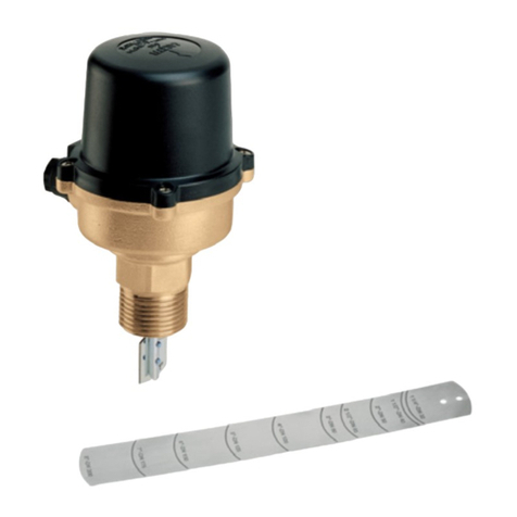
The Calef Series 626 water ow switch detects the presence or absence
of ow in pipework of heating, air conditioning, cooling and water treatment
systems as well as in pumping systems and process systems in general.
In heating systems the ow switch is normally used to shut off the burner
whenever there is no circulation of the carrier uid in the boiler circuit. A
lack of circulation would otherwise impair the operation of the temperature-
sensitive safety and protection devices.
Le ussostat Calef série 626 signale la présence ou l’absence de débit dans
une canalisation d’une installation de chauffage, climatisation, réfrigération,
traitement des eaux, ou dans systèmes de pompage, de remplissage, d’in-
troduction d’additifs et de tous procédés industriels.
Dans les installations de chauffage, le ussostat a pour mission d’arréter le
brûleur en cas d’absence de débit dans la chaudière pour éviter l’interven-
tion des dispositifs de sécurité et de protection sensibles aux variations de
température.
Der Strömungswächter Calef Serie 626 stellt das Vorhandensein oder
Fehlen von Durchuß in Heizungs-, Kühl- und Wasseraufbereitungsanlagen,
Pumpensystemen, Dosieranlagen und Prozeßsystemen im allgemeinen fest.
In Heizungsanlagen hat der Strömungswächter die Aufgabe, den Brenner
abzuschalten, sollte das Trägermittel in der Anlage nicht mehr oder nur in
ungenügendem Maß zirkulieren.
Das Fehlen von Durchuß beeinträchtigt das von der Temperatur
abhängige Funktionieren der Sicherheits- und Schutzeinrichtungen.
Impiego
Operation
Emploi
Einsatz
Empleo
Применение
H0001732.01
1
Code 626601
www.caleffi.com
© Copyright 2021 Caleffi
DE
FR
ES
RU

2
Technical
specications
Materials
Body: brass EN 12165 CW617N
Cover: self-extinguishing polycarbonate
Microswitch protection casing: self-extinguishing polycarbonate
Bellows rod and bellows: stainless steel
Paddle for pipes: stainless steel
Microswitch spring: stainless steel
O-Ring seals: EPDM
Performance
Medium: drinking water and glycol solutions
Max. percentage of glycol: 50 %
Max. working pressure: 10 bar
Medium temperature range: -30–120 °C
Max. ambient temperature: 55 °C
Connection: 1” M
Pipe adjustability: from 1 1/2” to 4”
Device: action type as per EN 60730-1 par 2,6 type 1
Electric specications
Voltage: max 250 V
Current: max 15 (5) A
Protection class: IP 54
Construction: incorporated control
El usostato para agua Calef, serie 626, detecta la presencia o ausencia
de ujo en las tuberías de instalaciones, de calefacción, acondicionamiento,
refrigeración, tratamiento de agua, en sistemas de bombeo, sistemas de
inyección de aditivos y sistemas de proceso en general. En las instalaciones
de calefacción, el usostato tiene la misión de provocar el paro del quemador
en el momento en el que falte uido vector, en el circuito de caldera. La falta
de circulación, perjudica el accionamiento de los dispositivos de seguridad y
de protección sensibles a la temperatura.
Реле потока воды обычно используется для обнаружения наличия/отсутствия
потока воды в трубопроводах систем отопления, кондиционирования,
охлаждения, водоподготовки, насосных систем, систем введения присадок
и технологических систем в целом. В системах отопления реле потока
служит для выключения горелки при отсутствии циркуляции теплоносителя
в контуре котла. Отсутствие циркуляции негативно влияет на срабатывание
чувствительных к температуре предохранительных и защитных устройств.

Installazione
Installation
Installation
Einbau
Instalación
Установка
Per una corretta installazione occorre attenersi alle seguenti istruzioni:
- tagliare la lamella contrassegnata con il diametro della tubazione sulla
quale l'apparecchio va installato;
- installare il ussostato sulla tubazione attenendosi al senso del usso
indicato dalla freccia stampigliata sul coperchio e sulla parte esterna del
corpo, ed in modo tale che la distanza tra la supercie superiore della
tubazione ed il punto di giunzione tra corpo e coperchio del ussostato
sia di 80 mm;
- il collegamento alla tubazione può essere effettuato saldando direttamente
un manicotto lettato, anche per il diametro di 1” in quanto le lamelle sono
studiate per essere contenute in dimensioni ridotte.
È tuttavia opportuno
controllare che la saldatura sia esente da bave nella
sua parte interna in
modo che la lamella possa ruotare liberamente nel
manicotto;
- l’apparecchio deve essere installato possibilmente con asta di comando in
posizione verticale per evitare depositi di impurità che causerebbero il non
corretto funzionamento.
To t the switch correctly follow these instructions:
- cut the blade marked with the diameter of the pipe in which the switch is
to be installed;
- t the ow switch to the pipe, carefully observing the direction of ow
indicated by the arrows stamped on the cover and on the switch mounting
plate. When tted, the distance between the upper surface of
the pipe and
upper surface of the switch mountuing plate should be 80 mm;
- the tee connection in the pipe can be formed by the direct welding of a
threaded socket;
- this also applies to a 1” diameter pipe, as the blades are designed to be
contained in these smaller dimensions. It is however advisable to check
that the weld is free from burrs on the inside so that the blade can move
freely in the tee connection;
- whenever possible the equipment should be installed with control stem in
the vertical position to avoid deposits of impurities which may cause it to
function incorrectly.
Pour une installation correcte, il est nécessaire de suivre les instructions
suivantes:
- choisir la languette correspondant au diamètre du tube où sera monté
le
ussostat;
- enlever les lamelles prévues pour des tubes d’un diamètre superieur, en
dévissant les vis de xation;
- pour les diamètres supérieurs ou égaux à 3” (DN 80), il faut rajouter la
lamelle longue, en la coupant au diamètre voulu;
- i
nstaller le ussostat sur la canalisation en vériant le sens de passage du
uide (indiqué par une èche sur le couvercle et sur l’extérieur du corps) La
distance entre le tube et la jonction corps/couvercle doit être de 80 mm;
- le raccordement à la canalisation peut être fait en soudant directe ment un
manchon leté. Ceci dès le 1”, car les lamelles sont sufsam ment étroites.
Il faut vérier la qualité interne de la soudure du manchon sur la canalisation,
an que la lamelle puisse manoeuvrer librement;
- il est préférable d’installer l’appareil sur une canalisation horizontale, monté
avec l’axe de commande à la verticale au-dessus de la
canalisation, an
d’éviter tous dépôts qui nuiraient au bon fonctionnement.
80 mm
20 mm
1"
1
1
2"
2
8"-DN200
6"-DN150
5"-DN125
4"-DN100
3"-DN 80
DN175
1 1/2”
DN 40
2”
DN 50
2 1/2”
DN 65
3”
DN 80
4”
DN 100
3

4
Für einen korrekten Einbau muß folgendes beachtet werden:
- Die richtige Größe des Paddels für den Durchmesser des Rohres an der
Montagestelle wählen.
- Die nicht benötigten Paddel durch Lösen der Schrauben entfernen.
- Für Rohrleitungen ≥ 3” (DN 80) muß auf die vormontierten das lange, bei-
liegende Paddel montiert werden, nachdem es vorher beim gewünschten
Nenndurchmesser abgeschnitten wurde
- Den Strömungswächter unter Beachtung der Fließrichtung (siehe
Pfeil auf
Deckel und Körper) so in die Rohrleitung einbauen, daß die Einbauhöhe,
gemessen von der Oberäche des Rohrs bis zum Verbindungspunkt von
Deckel und Körper
des Strömungswächters, 80 mm beträgt.
- Der Einbau ins Rohr erfolgt durch Anschweißen einer Muffe mit einem In-
nengewinde von G 1”. Es wird empfohlen, zu kontrollieren, daß im Inneren
keine Schweißgrate zurückgeblieben sind, damit sich das Paddel beim
Einschrauben frei in der Muffe drehen kann.
- Das Gerät muss mit dem Paddel nach unten in vertikaler Lage eingebaut
werden, um Ablagerungen auf dem Paddel vorzubeugen, die das korrekte
Funktionieren des Gerät beeinträchtigen würden.
Para una correcta instalación es necesario respetar las siguientes instrucciones:
- escoger la lámina marcada con el diámetro de la tubería sobre la cual el
aparato se instalará;
- quitar las láminas premontadas que sirven para diámetros superiores,
actuando sobre los tornillos de jación;
- para diámetros iguales o superiores a 3” (DN 80) añadir a la lámina pre-
montada mayor, la lámina larga, cortándola a la medida correspondiente
al diámetro deseado;
- instalar el usostato en la tubería, respetando el sentido del ujo indicado
en la echa impresa sobre la tapa,y sobre la parte externa del cuerpo, de
tal modo que la distancia entre la parte superior de la tubería y el punto de
unión entre cuerpo y tapa del usostato, sea de 80 mm;
- la unión con la tubería puede efectuarse, soldando directamente un man-
guito roscado, incluso para diámetro de 1” ya que las láminas están estu-
diadas para poder entrar en dimensiones reducidas. Es oportuno controlar
que la soldadura esté exenta de rebaba en la parte interna, de forma que
la lámina pueda girar libremente en el manguito;
- el aparato debe ser instalado, siempre que sea posible con varilla de a
accionamiento en posición vertical para evitar depósitos de impurezas que
causarían su no correcto funcionamiento.
Для обеспечения правильности установки придерживайтесь следующих
указаний:
-отрежьте лепесток по размеру, соответствующему диаметру трубопровода,
на котором будет установлен прибор;
-установите реле потока на трубопровод, соблюдая направление потока,
указанное стрелкой, выбитой на крышке и на внешней стороне корпуса,
таким образом, чтобы расстояние между верхним краем трубопровода и
точкой соединения корпуса и крышки реле потока составляло 80 мм;
-для обеспечения подсоединения к трубопроводу можно непосредственно
приварить к нему резьбовой патрубок, включая трубопровод диаметром
1”, т.к. лепестки рассчитаны на установку в трубопроводах малых размеров.
При этом следует убедиться в отсутствии заусениц с внутренней стороны
сварного шва для того, чтобы лепесток мог свободно поворачиваться
внутри патрубка;
-по возможности следует устанавливать прибор с управляющим штоком в
вертикальном положении; это необходимо для предотвращения отложения
загрязняющих веществ, которое может нарушить правильность работы.

5
Taratura
Calibration
Tarage
Einregelung
Regulación
Настройка
Nel caso la portata di intervento richiesta differisca da quella riportata nella
tabella di pag. 4, effettuare la correzione operando come segue: ruotare la
vite di taratura (A) in senso orario per ottenere la chiusura dei
contatti a valori
di portata più elevati o in senso antiorario per valori minori.
Effettuata la regolazione bloccare la vite (A) con la ghiera di ssaggio (B).
Evitare tassativamente qualsiasi intervento sulla vite di preregolazione
(C).
Un errato posizionamento pregiudicherà drasticamente
la funzionalità
dell’apparecchio.
If the required operating ow rate differs
from that given in the table at the end
of
the brochure the necessary correction
should be carried out as follows: turn
the calibration screw (A) in a clockwise
direction for the contacts to close at higher
ow rate values or in an anticlockwise
direction for lower ow rate values. When
the adjustment has been made lock the
screw (A)
with the locking ring nut (B). Avoid
all contact with the presetting screw (C).
An incorrect setting would seriously impair
the operation of the switch.
Au cas où le tarage réalisé en usine (voir page 10)
ne convient pas, il est pos-
sible d’effectuer une correction, en agissant de la façon suivante : tourner la
vis de réglage (A) dans le sens horaire pour avoir une fermeture des contacts
à des valeurs de débit plus élevées, et en sens contraire pour des valeurs
de débit plus faibles. Une fois le réglage réalisé, bloquer la vis (A) avec la
virole de blocage (B). Eviter absolument toute intervention sur la vis
de préréglage (C), une manœuvre maladroite nuirait gravement à la bonne
marche de l’appareil.
Falls der gewünschte Schaltpunkt von der in der Tabelle auf Seite 10 auf-
geführten Minimaleinstellung abweicht, ist wie folgt vorzugehen: Die Regel-
schraube (A) im Uhrzeigersinn drehen, um das Schließen der Kontakte bei
höheren Werten zu erreichen bzw. wieder gegen den
Uhrzeigersinn drehen, um niedrigere Werte zu erhalten. Nach erfolgter
Einstellung die Regelschraube (A) mit der Kontermutter (B) blockieren.
Jegliches Verstellen der Voreinstellungsschraube (C)
ist strikt zu ver-
meiden. Eine falsche Stellung dieser Schraube beeinträchtigt drastisch die
Funktionsweise des Geräts.
En el caso de que el caudal de intervención requerido sea diferente al
indica-
do en tabla de la pág. 10, efectuar las correcciones operando de la
siguiente
forma: girar el tornillo de regulación (A) en sentido horario, para obtener
el cierre de los contactos a valores de caudal más elevados o en sentido
contrario para valores menores. Efectuada la regulación, bloquar el tornillo
(A) con la brida de jación (B). Evitar cualquier intervención sobre el tor-
nillo de preregulación (C). Una mala regulación, perjudicará gravemente
el funcionamiento del aparato.
В случае, когда необходимая величина расхода отлична от приведенной
в таблице на стр. 4, действуйте следующим образом: поворачивайте
регулировочный винт (A) по часовой стрелке для обеспечения замыкания
контактов при большей величине расхода или против часовой стрелки для
обеспечения замыкания контактов при его меньшей величине.
После настройки
заблокируйте регулировочный винт стопорной гайкой (2).
Категорически запрещается осуществлять какое-либо воздействие
на винт предварительной настройки (C)
.
Неверная настройка серьезно
скажется на
правильности работы прибора.
A
B
C

6
Collegamenti
elettrici
Electrical
connections
Raccordements
électriques
Elektrisher
Anschluß
Conexiones
eléctricas
Электрические
соединения
Svitare le quattro viti di ssaggio e sollevare il
coperchio. Rimuovere la protezione in materiale
isolante posta sui morsetti del microinterruttore
esercitando una trazione verso l'esterno.
Non allentare le viti alle quali è ancorata la
protezione.
Unscrew the four xing screws and lift off the
outer cover. Remove the insulating cover located
on the terminals of the microswitch by carefully
lifting upwards.
Do not slacken the screws securing the inner cover.
Dévisser les 4 vis et démonter le couvercle. Enlever la protection en
matériau
isolant des bornes du microinterrupteur, en la tirant vers l’extérieur.
Ne pas manœuvrer les vis tant que la protection n’est pas enlevée.
Die vier Befestigungsschrauben lösen und den Deckel entfernen. Die
Schutzabdeckung aus isolierendem Material auf den elektrischen
Anschlüssen des Mikroschalters nach außen abziehen.
Keinesfalls die Schrauben, an denen die Schutzabdeckung verankert ist, lösen!
Desenroscar los cuatro tornillos de jación y levantar la tapa. Mover la
protección del material aislante de las conexiones del microinterruptor ejer-
ciendo tracción hacia el exterior.
No aojar los tornillos de la protección.
Открутите четыре крепежных винта и поднимите крышку. Снимите
защитную крышку из изоляционного материала, установленную на клеммах
микропереключателя, потянув ее на себя.
Не ослабляйте винты, которыми крепится защитная крышка
Collegare il cavo di messa a terra all’apposita vite evidenziata in gura.
Connect earth wire to its specic screw
Relier le câble de mise à la terre à la vis indiquée sur la gure.
Das Erdungskabel mit der in der Abbildung gezeigten
Erdungsschraube verbinden.
Conecte el cable de puesta a tierra al correspondiente tornillo,
indicado en la gura.
Подсоедините проводник заземления к соответствующему винту,
показанному на рисунке.

Rappresentazione schematica dei collegamenti interni del microinterruttore in:
Diagrams showing the internal connections of the microswitch with:
Représentation schématique des circuits du microinterrupteur :
Schematische Darstellung der internen Anschlüsse des Mikroschalters:
Representación esquemática de las conexiones internas del microinterruptor en:
Схематическое изображение внутренних соединений микропереключателя:
1
COM.
3
NO
2
NC
LINEA / INPUT / LINIE / LIGNE /
LÍNEA / LINHA / LIJN / ЛИНИЯ
CARICO / SWITCHED OUTPUT / LAST /
SORTIE / CARG / CARGA / VULLEN / НАГРУЗК
А
Flussostato utilizzato per attivare un dispositivo in
assenza di usso
Flow switch used to activate a unit on cessation of ow
Flussostat utilisé pour activer un appareil en cas
d’absence de débit
Einsatz des Strömungswächters zum Einschalten
eines Geräts bei Fehlen von Durchuß
Flusostato utilizado para activar un dispositivo en
ausencia de ujo
Реле потока, используемое для активации устройства
при отсутствии потока
Flussostato utilizzato per attivare un dispositivo in
presenza di usso
Flow switch used to activate a unit on commencement
of ow
Flussostat utilisé pour activer un appareil en cas de
présence de débit
Einsatz des Strömungswächters zum Einschalten
eines Geräts bei Vorhandensein von Durchuß
Flusostato utilizado para activar un dispositivo en
presencia de ujo
Реле потока, используемое для активации устройства
при наличии потока
1
COM .
3
NO
2
NC
LINEA / INPUT / LINIE / LIGNE /
LÍNEA / LINHA / LIJN / ЛИНИЯ
CARICO / SWITCHED OUTPUT / LAST /
SORTIE / CARG / CARGA / VULLEN / НАГРУЗК
А
Utilizzare cavi di collegamento elettrico scelti in base al carico. Pressacavo predisposto per cavi
di diametro da 5 a 8 mm.
For wiring use cables suitable for the load. Connector for cables with diameter from 5 to 8 mm.
Utiliser des câbles de connexion électrique en les choisissant en fonction de la charge. Serre-
câble pour câbles de 5 à 8 mm de diamètre.
Elektrische Anschlusskabel entsprechend der Last verwenden. Kabelverschraubung geeignet für
Kabel mit einem Durchmesser von 5 bis 8 mm.
Para la conexión eléctrica, utilice cables adecuados a la carga. Prensacables preparado para
cables con un diámetro de 5 a 8 mm.
Используйте электрические прповода, выбранные в соответствии с величиной нагрузки. Кабельный
ввод, рассчитанный на кабели диаметром от 5 мм до 8 мм.
7

Quando si raggiunge o si supera la portata di intervento con usso in
aumento, i contatti 1 e 3 del microinterruttore si chiudono, mentre si aprono
i contatti 1 e 2. Viceversa quando si raggiunge la portata di intervento con
usso in diminuzione si aprono i contatti 1 e 3 e si chiudono i contatti 1 e
2. Per installazioni con asta di comando in posizione verticale, occorre agire
sulla vite di taratura per individuare il punto ottimale di intervento.
When the operating ow rate is reached or exceeded with an increasing ow
contacts 1 and 3 of the microswitch close whilst contacts 1 and 2 open. This
is reversed when the operating ow rate with decreasing ow is reached and
contacts 1 and 3 open and contacts 1 and 2 close. For vertical installation,
it is necessary to regulate the setting screw in order to choose the optimal
working point.
Portata di intervento (m3/h)
Operating ow rate (m3/h)
Débit d’intervention (m3/h)
Durchußmenge am Schaltpunkt (m3/h)
Caudal de intervención (m3/h)
Расход срабатывания (м3/ч)
Diametro della tubazione
Диаметр трубопровода
Diameter of pipe
Nenndurchmesser des Rohres
Diametre du tube
Portata d'intervento con flusso in aumento
Operating flow rate with increasing flow
Schaltpunkt bei zunehmendem Durchfluß
Débit d'intervention avec augmentation de débit
Caudal de intervención con flujo en aumento
Caudal de intervenção com fluxo em aumento
Werkdebiet bij toenemende stroming
Taratura minima
Minimum calibration
Minimale Einstellung
Tarage minimum
Tarado mínimo
Regulação minima
Minimale afstelling
1 1/2"
2"
2 1/2"
3"
4"
4,5 6,2 9,1 10,5 16,2
3,4 3,7 5,7 6,5 12
11,3 13,8 21,9 30 42,3
11,2 13,6 20,6 29,7 42
Portata d'intervento con flusso in aumentp
Operating flow rate with increasing flow
Schaltpunkt bei zunehmendem Durchfluß
Débit d'intervention avec augmentation de débit
Caudal de intervención con flujo en aumento
Caudal de intervenção com fluxo em aumento
Werkdebiet bij toenemende stroming
Diámetro de la tuberia
Diâmetro da tubagem
Diameter van de leiding
Portata d'intervento con flusso in diminuzione
Operating flow rate with decreasing flow
Schaltpunkt bei abnehmendem Durchfluß
Débit d'intervention avec diminution de débit
Caudal de intervención con flujo en disminución
Caudal de intervenção com fluxo em diminuição
Werkdebiet bij afnemende stroming
Portata d'intervento con flusso in diminuzione
Operating flow rate with decreasing flow
Schaltpunkt bei abnehmendem Durchfluß
Débit d'intervention avec diminution de débit
Caudal de intervención con flujo en disminución
Caudal de intervenção com fluxo em diminuição
Werkdebiet bij afnemende stroming
Taratura massima
Maximum calibration
Maximale Einstellung
Tarage maximum
Tarado máximo
Regulação máxima
Maximale afstelling
Минимальная настройкаМаксимальная настройка
Расход срабатывания при возрастающем потоке
Расход срабатывания при убывающем потоке
8

L’installazione del ussostato deve essere eseguita da parte di
personale qualicato in accordo con la vigente normativa.
Se il ussostato non è installato, messo in servizio e mantenuto
correttamente secondo le istruzioni contenute in questo manuale, può
non funzionare correttamente e porre l’utente in pericolo.
Assicurarsi che tutta la raccorderia di collegamento sia a tenuta
idraulica
Nella realizzazione delle connessioni idrauliche, prestare attenzione a
non sovrasollecitare meccanicamente la lettatura del corpo valvola.
Nel tempo si possono produrre rotture con perdite idrauliche a danno
di cose e/o persone.
Temperature dell’acqua superiori a 50 °C possono provocare gravi
ustioni.
Durante l’installazione, messa in servizio e manutenzione del
ussostato, adottare gli accorgimenti necessari afnché tali
temperature non arrechino pericolo per le persone.
ATTENZIONE: Rischio di shock elettrico. Contatti
elettrici in tensione. Togliere l’alimentazione elettrica
prima di effettuare interventi. La mancata osservanza
di queste indicazioni può provocare danni a persone
o cose.
Lasciare il presente manuale ad uso e servizio dell’utente
Sicurezza
Safety
Sécurité
Sicherheit
Seguridad
Безопасность
Quand on atteind ou dépasse le débit d’interventation en augmentation de
débit, les contacts 1 et 3 se ferment, pendant que s’ouvrent les contacts 1
et 2. Inversement, quand on atteind ou dépasse le débit d’intervention en
diminution de débit, les contacts 1 et 2 se ferment, pendant que s’ouvrent
les contacts 1 et 3. En cas d’installation sur une canalisation verticale, agir
sur la vis de tarage pour déterminer le point optimum d’intervention.
Wenn bei zunehmendem Durchuß der Schaltpunkt erreicht bzw. übers-
chritten wird, schließt sich der Kontakt 1 - 3 des Mikroschalters, während
sich der Kontakt 1 - 2 öffnet. Wird umgekehrt bei abnehmendem Durchuß
der Schaltpunkt erreicht, öffnet sich der Kontakt 1 - 3 des Mikroschalters,
während sich der Kontakt 1 - 2 schließt. Bei senkrechter Installation die Re-
gelschraube betätigen, um einen optimal Schaltpunkt einzustellen.
Cuando se alcanza o se supera el caudal de intervención con ujo en au-
mento, los contactos 1 y 3 del microinterruptor se cierran, mientras se abren
el 1 y 2.
Cuando se alcanza el caudal de intervención con ujo en disminución, se
abren los contactos 1 y 3 y se cierran los contactos 1 y 2. Para instalaciones
verticales, es necesario intervenir sobre el tornillo de preregulacion buscando
el punto optimal de intervento
При достижении или превышении расхода срабатывания при возрастающем
потоке контакты 1 и 3 микропереключателя замыкаются, в то время как контакты
1 и 2 размыкаются. И наоборот, при достижении расхода срабатывания при
убывающем потоке размыкаются контакты 1 и 3, и замыкаются контакты 1 и 2. В
случае установки с вертикальным положением управляющего штока используйте
калибровочный винт для задания оптимальной точки срабатывания.
9

The installation of the ow switch must be performed by qualied
personnel in concordance with the current regulations.
If the ow switch are not installed, commissioned and maintained
properly according to the instructions contained in this manual, they
may not operate correctly and may place the user in danger.
Make sure that all the pipe connections are watertight.
During the realization of the hydraulic connections, be careful not
to mechanically over-stress the screw-thread of the valve body.
Otherwise, over time, breakages can occur with hydraulic leaks causing
damage to property and/or persons.
Water temperatures greater than 50 °C can cause serious burns.
During the installation, commissioning and maintenance of the zone
valves, take all the necessary steps to ensure that such temperatures
do not cause danger to people.
ATTENTION: Risk of electric shock. Live
motorised control system. Switch off the power
supply before performing maintenance or other
operations. Failure to follow these directions may
cause damage to persons or property.
Leave this operating manual with the user
Le ussostat doit être installé par du personnel qualié conformément
aux normes en vigueur.
Si le flussostat n’est pas installé, mise en service et entretenu
correctement selon les instructions contenues dans ce manuel, il
peut ne pas fonctionner correctement et causer des dégats
matériels et/ou des blessures aux personnes.
S’assurer de l’étanchéité de tous les raccordements.
Dans la réalisation des connections hydrauliques, prêter attention à ne
pas serrer de façon excessive les raccords sur l’appareil.
Cela pourrait provoquer avec le temps des ruptures et donc des fuites.
Des températures d’eau supérieures à 50 °C peuvent provoquer de
graves brûlures.
Au cours du montage, de la mise en service et de l’entretien des
ussostats, prenez les mesures nécessaires pour éviter tous risques
de brûlure.
ATTENTION: Risque d’électrocution. appareil sous
tension. Coupez l’alimentation électrique avant d’ef-
fectuer toute intervention. Le non respect de ces indi-
cations peut provoquer des lésions corporelles ou
des dégâts matériels.
Laisser ce manuel à disposition de l’utilisateur
10

Die Installation muss von qualizierten Personen, unter Beachtung der
gültigen Normen, durchgeführt werden.
Bei unsachgemäßem Einbau und unsachgemäßer Handhabung sowie
nicht korrektem Vorgehen gemäß diesem Handbuch kann das Ventil
nicht einwandfrei funktionieren und sogar Sachschäden und Perso-
nenschäden verursachen.
Vergewissern Sie sich nach dem Einbau, ob alle Anschlussteile auch
dicht sind.
Während man die hydraulischen Anschlüsse installiert, darauf achten,
dass die Anschlussarmaturen am Ventil nicht mechanisch überspannt
werden.
Temperaturen über 50 °C führen zu schlimmen Verbrühungen.
Deshalb während des Einbaus der Inbetriebnahme und der Wartung
des Ventil immer darauf achten, dass keine Gefahr für die Personen
entstehen kann.
ACHTUNG: Stromschlaggefahr. Stellantrieb
unter
Spannung. Vor Eingriffen unbedingt die Stromver-
sorgung unterbrechen. Nichtbeachtung dieser
Hinweise kann Schäden an Personen oder Sachen
hervorrufen.
Diese anleitung ist dem benutzer auszuhändigen
El usostato debe ser instalado por personal especializado y de con-
formidad con las normas vigentes.
Si la instalación, la puesta en servicio y el mantenimiento del usosta-
to no se realizan de acuerdo con lo indicado en este manual, las
válvulas pueden no funcionar correctamente y poner en peligro al
usuario.
Controle que todos los racores sean perfectamente estancos.
Al realizar las conexiones hidráulicas, tenga cuidado de no forzar
mecánicamente la rosca del cuerpo de la válvula. Con el tiempo po-
drían vericarse pérdidas de agua con los consiguientes daños mate-
riales o personales.
Las temperaturas del agua superiores a 50 °C pueden causar quema-
duras graves. Durante la instalación, la puesta en servicio y el mante-
nimiento de las válvulas de zona, tome las precauciones necesarias
para que dichas temperaturas no provoquen daños personales.
ATENCIÓN: Riesgo de choque eléctrico. Mando mo-
tor con tensión. Corte la alimentación eléctrica antes
de efectuar cualquier operación. El incumplimiento de
estas indicaciones puede provocar daños materiales o
personales.
Entregar este manual al usuario
11

12
Монтаж реле потока должен осуществляться квалифицированными
специалистами в соответствии с действующими нормативами.
В случае выполнения монтажа, ввода в эксплуатацию и техобслуживания
реле потока, не в соответствии с указаниями, приведенными в данном
руководстве, оно может функционировать неверно и представлять
опасность для потребителя.
Убедитесь, что все соединительные фитинги обеспечивают надежную
гидравлическую герметичность.
При выполнении гидравлических соединений следите за тем, чтобы не
сорвать резьбу корпуса клапана. В противном случае со временем
возможны поломки с образованием утечек воды, которые могут
причинить травмы и/или материальный ущерб.
Температура воды выше 50 °C может стать причиной серьезных ожогов.
При установке, вводе в эксплуатацию и техобслуживании реле потока
предпринимайте необходимые меры для того, чтобы такая температура
не создавала опасности для людей.
ВНИМАНИЕ! Опасность поражения электрическим
током. Электрические контакты под напряжением. Перед
тем как приступать к выполнению работ, отключите
электропитание. Несоблюдение этих указаний может
привести к травмам или материальному ущербу.
Данное руководство следует передать в распоряжении потребителя
Other CALEFFI Switch manuals
Popular Switch manuals by other brands

Optex
Optex SW-1 installation manual

Netis
Netis ST-3105 Quick installation guide

Interlogix
Interlogix IFS ANT-OMN-15DB-2G quick start guide

Abocom
Abocom HS2080 specification

Allied Telesis
Allied Telesis AT FS708LE AT-FS708LE AT-FS708LE datasheet

Allied Telesis
Allied Telesis IE340-12GP Quick installation guide

Hubbel
Hubbel Chance BP3 Installation, operation and maintenance manual

Intellinet
Intellinet IPS-54GM06-10G-450W instructions

Cross Technologies
Cross Technologies 2582-122 instruction manual

Cisco
Cisco Catalyst 4500 Series Command reference guide

Surecom
Surecom EP-802X user manual

Goobay
Goobay 71223 user manual