Calian SatService sat-nms LF20 User manual

20 Slot Optical Links
sat-nms LF20
User Manual
Version 1.2.008
© Copyright
SatService Gesellschaft für Kommunikationssysteme mbH
Hardstrasse 9
D-78256 Steisslingen
satnms-support@satservicegmbh.de
www.satnms.com
www.satservicegmbh.de
Tel +49 7738 99791-10

Table Of Contents
1Table Of Contents ...............................................................................................................................
3sat-nms LFTX/RX LF20 User Manual ................................................................................................
41 Introduction ......................................................................................................................................
51.1 Compliances .............................................................................................................................
51.1.1 CE Compliances .................................................................................................................
62 Installation ........................................................................................................................................
62.1 Safety Instructions .....................................................................................................................
72.2 Handling instructions for optical connectors .............................................................................
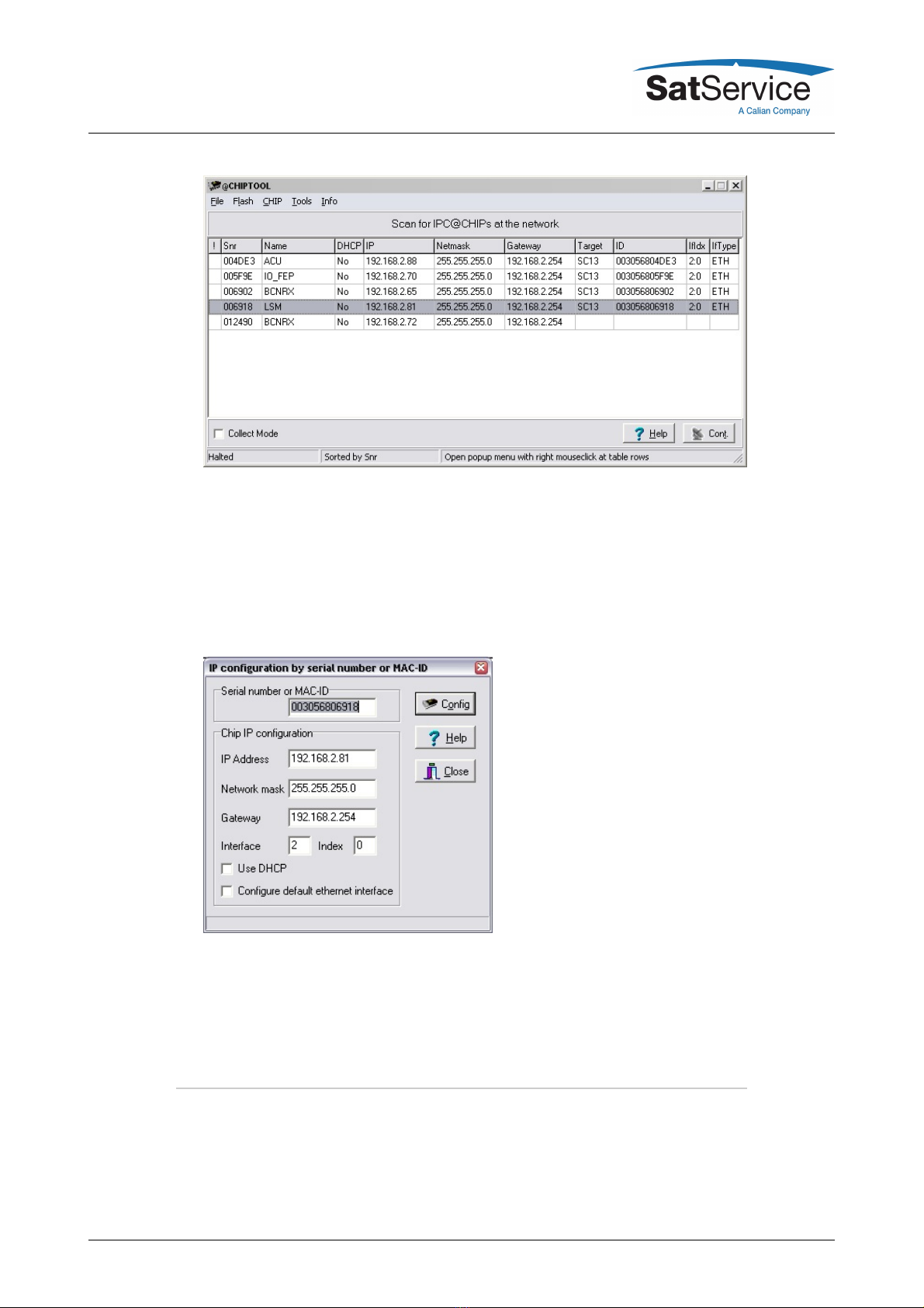
82.3 Setting the IP Address ...............................................................................................................
92.4 Mechanical installation ..............................................................................................................
102.5 Connecting the sat-nms LFTXRX ...........................................................................................
112.5.1 Optical receiver ,transmitter and switch cards .................................................................
122.5.2 Power connectors and power supplies ............................................................................
122.5.3 DC and data connectors ...................................................................................................
132.5.4 RF connectors ..................................................................................................................
142.5.5 Optical connectors ............................................................................................................
152.5.6 optional 75Ohm converter ................................................................................................
152.5.7 optional 1:4 splitter 'LFRXv4' .............................................................................................
152.5.8 optional dual coupler 'LFC10TX' and 'LFC10RX' ..............................................................
162.6 Configuring the Optical Links ..................................................................................................
162.7 Line-up the Optical Links .........................................................................................................
173 Operation .......................................................................................................................................
173.1 The Web-based User Interface ...............................................................................................
173.2 State: Display Readings ..........................................................................................................
183.2.1 Reading of LFRX receiver card ........................................................................................
193.2.2 Reading of LFTX transmitter card ....................................................................................
203.2.3 Reading of LFSW switch card ..........................................................................................
213.2.4 Reading of empty slots .....................................................................................................
223.3 Configuration of operational parameters .................................................................................
223.3.1 Configuration of LFRX receiver card ................................................................................
233.3.2 Configuration of LFTX transmitter card ............................................................................
253.3.3 Configuration of LFSW switch card ..................................................................................
263.3.4 Empty slots .......................................................................................................................
263.4 General Setup .........................................................................................................................
283.5 Local operation LFTX, LFRX, LFSW Card .............................................................................
283.5.1 Local operation LFTX Card ...............................................................................................
293.5.2 Local operation LFRX Card ..............................................................................................
303.5.3 Local operation LFSW Card .............................................................................................
314 Remote Control .............................................................................................................................
314.1 General command syntax .......................................................................................................
324.2 The TCP/IP remote control interface ......................................................................................
324.3 The RS232 remote control interface .......................................................................................
334.4 SNMP Control ..........................................................................................................................
344.5 Parameter list ..........................................................................................................................
375 Theory of Operation .......................................................................................................................
(C) 2021, SatService GmbH www.satnms.com LF20-UM-2107 Page 1/43

395.1 Frequency bands ....................................................................................................................
405.2 Connectors ..............................................................................................................................
405.3 Controller Module ....................................................................................................................
415.4 Redundancy switching ............................................................................................................
415.5 Outline Drawing .......................................................................................................................
426 Specifications ................................................................................................................................
(C) 2021, SatService GmbH www.satnms.com LF20-UM-2107 Page 2/43

sat-nms LFTX/RX LF20 User Manual
Version 1.2.008 -- 2021-07-29 -- © 2020-2021 SatService GmbH
Abstract
This document is the user manual provided with the sat-nms LFTXRX fibre optical link
equipment. It contains all necessary information how to install, setup, and operate the unit.
The user manual is available as a printed document and for on-line reading on the optical
links itself as well.
Table Of Contents
1 Introduction
1.1 Compliances
1.1.1 CE Compliances
1.1.1.1 EMC compliance
1.1.1.2 Safety compliance
2 Installation
2.1 Safety Instructions
2.2 Handling instructions for optical connectors
2.3 Setting the IP Address
2.4 Mechanical installation
2.5 Connecting the sat-nms LFTXRX
2.5.1 Optical receiver ,transmitter and switch cards
2.5.2 Power connectors and power supplies
2.5.3 DC and data connectors
2.5.4 RF connectors
2.5.5 Optical connectors
2.5.6 optional 75Ohm converter
2.5.7 optional 1:4 splitter 'LFRXv4'
2.5.8 optional dual coupler 'LFC10TX' and 'LFC10RX'
2.6 Configuring the Optical Links
2.7 Line-up the Optical Links
3 Operation
3.1 The Web-based User Interface
3.2 State: Display Readings
3.2.1 Reading of LFRX receiver card
3.2.2 Reading of LFTX transmitter card
3.2.3 Reading of LFSW switch card
3.2.4 Reading of empty slots
3.3 Configuration of operational parameters
3.3.1 Configuration of LFRX receiver card
3.3.2 Configuration of LFTX transmitter card
3.3.3 Configuration of LFSW switch card
3.3.4 Empty slots
3.4 General Setup
3.5 Local operation LFTX, LFRX, LFSW Card
(C) 2021, SatService GmbH www.satnms.com LF20-UM-2107 Page 3/43

3.5.1 Local operation LFTX Card
3.5.2 Local operation LFRX Card
3.5.3 Local operation LFSW Card
4 Remote Control
4.1 General command syntax
4.2 The TCP/IP remote control interface
4.3 The RS232 remote control interface
4.4 SNMP Control
4.5 Parameter list
5 Theory of Operation
5.1 Frequency bands
5.2 Connectors
5.3 Controller Module
5.4 Redundancy switching
5.5 Outline Drawing
6 Specifications
1 Introduction
The sat-nms LFTXRX fibre optical link is a high performance transmission system which transmits
a complete frequency band, with all its separate carriers, over a single mode fibre with length up
to 5km. The big advantages of fibre optical links are:
Lightning protection
Fully isolated between the two destinations
No ground loops
bug proof
Two types of optical converters are available
sat-nms LFTX --- optical transmitter which converts from IF input spectrum to optical output
at 1310nm
sat-nms LFRX --- optical receiver which regenerates the optical signal back to an IF
spectrum
SatService offer the LFTXRX modules for different frequency bands.
sat-nms LFRX-L and LFTX-L --- 950 to 2150MHz
sat-nms LFRX-B and LFTX-B --- 50 to 2150MHz
sat-nms LFRX-10 and LFTX-10 --- 950 to 2150MHz and 10MHz reference frequency for
BUC
sat-nms LFRXO10 and LFTXO10 --- 10MHz only
Additional there are optional modules available which will be supported by the software and the
backplane
sat-nms LFSW --- RF-Transfer Switsch which allowes to build redundancy paths with the
optical link
sat-nms TBD --- More modules are possible, please define your request
The paragraphs below give a short overview to the contents of the documentation. A subset of
this documentation is stored on the device itself, the complete documentation is available on the
sat-nms documentation CD and at www.satnms.com.
(C) 2021, SatService GmbH www.satnms.com LF20-UM-2107 Page 4/43

Installation : The installation chapter guides through the installation and setup of the sat-
nms LFTXRX. It describes the mechanical concept of the chassis and the assignment of the
connectors. Finally you learn in this chapter how to set the sat-nms LFTXRX's IP address,
which is a essential precondition to operate the sat-nms LFTXRX by means of a web
browser. This section is available in the printed version only.
Operation : The sat-nms LFTXRX is operated using a standard web browser like the
Internet-Explorer or Mozilla Firefox. The user interface design is straight forward and clearly
structured. Operating the sat-nms LFTXRX is mostly self-explanatory. Nevertheless, the
'Operation' chapter outlines the map of web pages which make up the sat-nms LFTXRX user
interface and elaborately describes the meaning of each alterable parameter.
Remote Control : The sat-nms LFTXRX provides a versatile remote control interface. A
monitoring & control software may fully operate the sat-nms LFTXRX either through a
TCP/IP network connection or through the RS232 interface of the sat-nms LFTXRX. This
chapter describes the communication protocol used for remote control and lists all
parameters accessible through the remote interface.
Theory of Operation : This chapter gives a short overview how the optical links work and
which features are supported.
Specifications : At the end of the document, the specifications applicable to the sat-nms
LFTXRX are summarized in this chapter.
Support and Assistance
If you need any assistance regarding our sat-nms Optical Links, don't hesitate to contact us. We
would be pleased to help you by answering your questions.
SatService GmbH
Hardstrasse 9
78256 Steisslingen
Germany
phone +49 7738 99791-10
www.satnms.com
1.1 Compliances
1.1.1 CE Compliances
1.1.1.1 EMC compliance
This equipment has been tested and meets the specification of following EMC standards:
EN 55032
EN 55024
FCC, part 15B
ICES003 To meet all EMC requirements it is necessary to keep with the cabling requirements
mentioned in the installation chapter.
1.1.1.2 Safety compliance
(C) 2021, SatService GmbH www.satnms.com LF20-UM-2107 Page 5/43

This equipment has been tested and meets the specification of following safety standards:
EN 60950
EN 62368 Every single delivered unit is tested according to EN 60950 to ensure best
possible user safety.
To meet all safety requirements it is necessary to keep with the cabling requirements mentioned
in the installation chapter.
2 Installation
This chapter describes how to install the sat-nms LFTXRX Fibre Optical Link. You find a guide
how to connect, configure and mechanically mount the equipment below.
Before you start, please first read the Safety Instructions chapter below. It contains some
important recommendations to prevent damage from the equipment.
Then, we strongly recommend to do a first setup of the unit on a lab desk before installing it at it's
final location. This is mainly for the following reason:
1. To setup the IP parameters, the PC used for configuring and the chassis must either be
connected to the same Ethernet hub / switch or must be connected directly with a crossover
cable. The initialization program does not work through routers intelligent or network
switches.
Hence, the typical sequence of tasks when putting an sat-nms LFTXRX into operation is as
follows:
1. Read the chapter Safety Instructions
2. Set the unit's IP address
3. Mechanically installation of the chassis
4. Connecting the LFTXRX
5. Configuring the LFTXRX
2.1 Safety Instructions
Failure to observe all Warnings and Cautions may result in personnel injury and/or equipment
damage not covered by the warranty.
The equipment described in this manual is designed to be installed and used by
properly trained personnel only!
ATTENTION inv isible Optical Radiation! If connected to a
power supply, the unit provides invisible Laser-radiation. The source is class 3R Laser diode
as defined in DIN EN 60825-1:2001-11. P0=2mW, Lambda=1310nm.
Never look into fibre-optical components like connectors or fibres. Use an infrared
viewer, optical power meter or fluorescent screen for optical output verification.
Do not allow any dirt or foreign material to get into the optical connector bulkheads. This
(C) 2021, SatService GmbH www.satnms.com LF20-UM-2107 Page 6/43

may cause damage to the polished optical connector end faces
Follow standard Electrostatic Discharge (ESD) procedures when handling a the chassis and
the modules of the LFTXRX.
The ground terminal of the device has to be permanently connected to a grounding point for
save operation. Otherwise, the device could be damaged.
The power supplies are EMI filtered. The chassis is connected to earth ground in compliance
with safety requirements. Always use the 3-prong AC plug with earth ground to avoid
possibility of electrical shock hazard to personnel.
Select and apply the appropriate 100-240AC voltage according to the data sheet and
documentation before connecting power.
Install suitable overvoltage protection to ensure that no overvoltage (such as that caused by
a bolt of lightning) or overcurrent can reach the product. Otherwise, the person operating
the product will be exposed to the danger of an electric shock.
Depending on configuration, the chassis is equipped with user-changeable power supplies.
Always disconnect the mains of the power supply that has to be changed. Wait at least 10s
after disconnecting the mains (for internal discharge of the power supply) before removing
the power supplyATTENTION: To avoid the possibility of an electrical shock, never handle
with a power supply that is connected to mains!
Before you connect the LFTXRX to an L-Band distributor or LNC , please make sure that the
unit to which you connect can handle 15V D/C voltage on its RF L-Band input. Some L-Band
IF distribution equipment does not have D/C blocks included and the unit could be damaged.
If you are not sure how the interfacing equipment will behave, switch off the LNC supply
voltage in the Setup menu or in case of local controlling by hardware switch before you
connect the cable.
The LFTXRX can be damaged if the total RF input power is higher than +10dBm specified
maximum value. Do not connect equipment where the total output power is higher than the
specified value of the data sheet or indicated on the LFTXRX unit.
In case of a failure do not open the sat-nms LFTXRX, you will loose warranty, call SatService
GmbH for a RMA number.
Observe normal safety precautions when operating, servicing, and troubleshooting this
equipment.
Take standard safety precautions with hand and/or power tools.
When connecting the units fault relay circuits, observe the maximum ratings: 48V D/C
300mA, 48V A/C 500mA.
2.2 Handling instructions for optical connectors
Do not allow any kind of dust or dirt on the fibre.
Do not touch the fibre! Otherwise you will get optical attenuation and the opposite fibre in the
corresponding connector will be contaminated as well.
When installing or changing optical connections, ensure that the environment of the room
where the unit is installed is as dust-free as possible.
If you install the unit on-site, make sure that the complete work that causes dust (e.g.
plastering or concreting) is already finished and the resulted dust is cleaned up properly.
Remove the fibre protection cap of the E2000 or FC/APC connectors just before you
connect the optical connector.
Store the protection caps in a closable box that is absolutely dirt- and dust-free.
After disconnecting a fibre, put a dirt- and dust-free protection cap into the connector in
order to avoid dust contamination.
Before connecting, we strongly recommend to clean the fibre. We recommend to use clean
(C) 2021, SatService GmbH www.satnms.com LF20-UM-2107 Page 7/43

compressed air spray like e.g. 'Kontakt 334' or a special cleaning device like e.g. 'CLETOP'
or 'one click cleaner'. Do not use compressed air produced by a standard air compressor,
this air is not clean enough! If a dirty fibre (e.g. contaminated with dust) is connected to a
LFRX or LFTX card, the internal fibre of the LFTX or LFRX card will be contaminated as well
and you will get optical attenuation. In the worst case, the fibre-end might be irreparably
damaged and has to be replaced.You always have to consider: optical attenuation
causes a twice RF-signal attenuation! So e.g. an optical attenuation of 2dB causes 4dB
RF signal attenuation.
2.3 Setting the IP Address
Before you can operate the sat-nms LFTXRX Optical Link, you need to set the unit's IP address.
There is a special configuration program on the documentation CD shipping with the unit for this
purpose. We recommend to configure LFTXRX' TCP/IP settings before you install chassis at it's
final place. To configure LFTXRX, the following equipment is required:
The sat-nms LFTXRX L-Band Optical Link itself
110-240V A/C power
A Computer running a Microsoft Windows operating system equipped with CD-ROM drive
and Ethernet network card.
A CAT5 crossover network cable or a Ethernet hub/switch and standard network cables to
connect the LFTXRX and the computer.
The CD-ROM shipping with the sat-nms LFTXRX.
Setting the chassis' IP parameters now is easily done within a few minutes.
1. First install a network cable between the LFTXRX chassis and your computer. If you have a
crossover cable available, this is very easy: simply put the cable into the network connectors
of computer and LFTXRX chassis. Without a crossover cable, you need to connect both, the
computer and LFTXRX chassis to the same network hub or switch using two standard
network cables. It is essential, that the computer and the LFTXRX chassis are connected to
the same network segment, the configuration program is not able to find the LFTXRX chassis
through routers or network switches.
2. Now power on your computer and connect LFTXRX chassis to the 110-240V A/C supply.
3. Insert the CD-ROM into the computer's drive and inspect it's contents through the 'My
Computer' icon on your desktop. Double-click to the 'ChipTool.exe' program in the 'ChipTool'
directory.
4. When the ChipTool program is running, type CTRL+F to make the program search the
LFTXRX. The program shows a list containing at least one entry describing the actual
network parameters of the LFTXRX.
(C) 2021, SatService GmbH www.satnms.com LF20-UM-2107 Page 8/43

5. The serial number shown in the first column of the list, must match the serial number printed
on the processor's enclosure. If the list stays empty, the LFTXRX chassis is not connected
properly. If there are more entries in the list, the configuration program has found other
devices in this network segment which use the same technology.
6. Now type CTRL+I to open the IP configuration window of the program. In this form enter the
processor's serial number, it's new IP address and network mask. If the LFTXRX later shall
be operated through a router, enter the address of the router on the gateway field, otherwise
leave this field blanc. Be sure, that the 'DHCP' mark is unchecked. Finally click to the 'Yes'
button to set the new parameters at the LFTXRX chassis.
Now the IP configuration of the chassis is completed. You may finally want to test if the LFTXRX
chassis is reachable now. Start your web browser and type the chassis' IP address into the URL
field of the browser. The LFTXRX should reply with it's main page, provided that the chassis and
your computer are configured for the same subnet.
2.4 Mechanical installation
The sat-nms LFTXRX enclosure is a standard 3HU 19" rack-mountable enclosure. Use slide bars
to install the chassis, because the mounting angles will not be able to hold the chassis in the
horizontal position. Fix the enclosure with 4 according screws to a 19" Rack. Don't forget to
connect the "GND"-screw to the Rack.
To ensure sufficient airflow for cooling the unit, we recommend to keep 1RU free space below and
(C) 2021, SatService GmbH www.satnms.com LF20-UM-2107 Page 9/43

above the unit. If you have not enough rack-space for meeting this requirement, call SatService
to develop a suitable solution.
When planning the mechanical installation of the chassis, please consider that the connectors
are placed at the front and the backside of the enclosure. Depending on the flexibility of the
cables you are going to use, you will require about 10 centimetres space for cabling on both
sides of the chassis.
2.5 Connecting the sat-nms LFTXRX
The connectors of the chassis are placed on the front and on the rear side. The Front side
contains the fibre optic connectors and the L-Band test-ports, the rear side contains the
corresponding L-Band In/Out connectors and also the the AC-power and Data-connectors.
When you connect the L-Band Optical Link chassis, please consider the following:
J1.2 LAN is the Ethernet 10/100Base-T / RJ45 connector. Use a standard network cable to
connect the LFTXRX to an Ethernet hub or switch. If you want to connect your computer and
the unit directly without using a hub, you need a crossover cable for this with swapped RX/TX
lines. To meet mentioned EMC standards, use double shielded twisted pair CAT7 S/FTP
Network cable, e.g. DRAKA UC900 SS27 Cat.7 PUR. Take care, that cable shielding is
connected properly.
J1.1 serial is a standard 9-pin RS232 (DCE) SUB-D pin-connector. You may use a direct 9-
pin cable to connect a PC to the LFTXRX. To meet mentioned EMC standards, use double
shielded twisted pair CAT7 S/FTP Network cable, e.g. DRAKA UC900 SS27 Cat.7 PUR. Take
care, that cable shielding is connected properly.
J1.3 Alarm is a standard 9-pin SUB-D socket-connector. This connector contains the alarm
contacts of the internal failure relays. To meet mentioned EMC standards, use double
shielded twisted pair CAT7 S/FTP Network cable, e.g. DRAKA UC900 SS27 Cat.7 PUR. Take
care, that cable shielding is connected properly.
PS1 and PS2 are mains power-inputs. Only use IEC plugs with an earthing contact and
protective earth connection to connect the power supplies. Do not forget to connect the
"GND"-labelled screw to the PE potential.
The input, output and test-port RF-connectors are all SMA/50Ohm female in the standard
(C) 2021, SatService GmbH www.satnms.com LF20-UM-2107 Page 10/43

configuration. 75Ohm F-type is available on special request. Use double shielded coaxial
cables, e.g. RG223, only.
The fibre optic connectors are E2000 or FC/APC types depending on the configuration. It is
essentially to use single mode cables with 8° angled polish for proper function.
2.5.1 Optical receiver ,transmitter and switch cards
Attention: Optical Radiation!
If connected to a power supply, the LFTXRX provides invisible laser radiation. The source is class
3R Laser diode as defined in DIN EN 60825-1:2001-11 with P0=2mW, Lambda=1310nm. Never
look into fibre-optical components like connectors or fibres. Use an infrared viewer, optical power
meter or fluorescent screen for optical output verification.
It is possible to realize up to 20 optical links with one sat-nms LFTXRX chassis. Alternativ it is
possible to plug in a sat-nms LFSW card, which allow to realize a rf redundancy switching.
Please keep in mind that each sat-nms LFSW will need one slot in the chassis.
On the front side of the enclosure, you find 20 slots, where up to 20 cards can be placed in.
Read chapters Config Parameters and Setup Parameters for instructions how to use this
configuration and how to configure the redundancy.
It is possible to place a LFRX, LFTX or LFSW card in every slot. To install the desired card, put it
into the slide rail until the front plate of the card contacts the mounting rail. The card has to slide
in smoothly. If not, pull the card out and try again. Otherwise the connectors on the card edge or
on the backplane might be damaged. After that fix the card with the provided screws to ensure a
proper contacting of the connectors on the LFRX, LFTX or LFSW card with the connectors on the
backplane.
Now you have to configure the system after placing a LFRX, LFTX or LFSW card. How to do this,
is described in chapter Config Parameters .
To release a card, open the screws with which the card is fixed at the mounting rail. Now turn in
the screw into the screw thread beside to push the card out of its socket. After that you can pull
the card out of the unit.
(C) 2021, SatService GmbH www.satnms.com LF20-UM-2107 Page 11/43

2.5.2 Power connectors and power supplies
Power connectors
At first, connect the screw, labelled with "GND" to Ground (e.g. to the 19"-Rack the chassis is
mounted in).
After that connect the chassis to 90-240V A/C via IEC connectors. Use power cords with an
earthing contact and protective earth connection only! The sat-nms LFTXRX is working with only
one connected power supply as well, but we strongly recommend to use two different power
supplies to ensure the maximum system availability. In case of one power supply breaking down,
the system will still be working without interrupt.
Power supplies
The sat-nms LFTXRX frame is equipped with hot-swap power supply, Therefore the power
supplies can be changed during the sat-nms LFTXRX frame is in operation. To change a power
supply, always disconnect the mains of the power supply that has to be changed and wait at least
10s (for internal discharge). Open the 2 screws with which the power supply is mounted an pull
the power supply, using the attached handle bar, out of the unit.
To put in a power supply, you have to do the same things in reverse chronology: Put the power
supply into the slide rails, until the front plate contacts the mounting rail. After that fix the power
supply with the provided screws to ensure a proper contacting of the connectors on the power
supply with the connectors on the backplane.
ATTENTION: To avoid the possibility of an electrical shock, never handle with a power supply that
is connected to mains!
2.5.3 DC and data connectors
The Alarm and data connectors of the sat-nms LFTXRX chassis all are located at the front side of
the enclosure. The figure below illustrates the location of the connectors and the pin out.
To meet mentioned EMC standards, use double shielded twisted pair CAT7 S/FTP Network cable,
e.g. DRAKA UC900 SS27 Cat.7 PUR, for connecting network, serial and alarm interfaces. Ensure
that the shield is connected properly.
The LED PS/Alm shows the presence of one or two power supply(ies) and the Alarm state of the
Unit. The LNK/Traffic LED turns on, when there is some traffic on the LAN, the chassis is
connected to.
To release the MNC board, open the screws with which the card is fixed at the mounting rail. Now
turn in the screw into the screw thread beside to push the card out of its socket. After that you
can pull the card out of the unit.
To install the MNC board again, put it into the slide rail until the front plate of the card contacts the
mounting rail. Please pay attention: The board has to slide in smoothly. If not, pull the card out
and try again. Otherwise the connectors on the MNC board or on the backplane might be
damaged. After that fix the card with the provided screws to ensure a proper contacting of the
connectors on the MNC board with the connectors on the backplane.
(C) 2021, SatService GmbH www.satnms.com LF20-UM-2107 Page 12/43

J1.1 Alarm connector
Dry alarm relay contacts represent a summary fault state of the unit. Both relays do switch
parallel and show always the same state.
Pin Alarm contacts (DSUB-9 male)
1 NC1 closed if ok, open in fault state
2 COM1 common for fault relay 1.te .ts 3
4 not connected
5 not connected
6 NC2 closed if ok, open in fault state
7 COM2 common for fault relay 2.te .ts 8
9 not connected
J1.3 Serial connector
Pin RS232 serial interface (DCE) (DSUB-9 female}
1 not connected
2 TxD (output)
3 RxD (input)
4 not connected
5 GND
6 not connected
7 not connected
8 not connected
9 not connected
J1.2 Ne twork Connector
Ethernet 10/100Base-T (RJ45)
2.5.4 RF connectors
On the rear side the in-/ out RF-connectors are placed. Depending, which card is placed in the
(C) 2021, SatService GmbH www.satnms.com LF20-UM-2107 Page 13/43

corresponding slot, the connector is an in- or an output.
If e.g. in slot 1 a LFTX card is placed, the connector I/O 1 is a RF-input. If there is placed a LFRX-
card, I/O 1 is a RF-output.
In the standard configuration all RF-connectors are SMA/ 50Ohm female connectors. If you need
other connectors e.g. BNC or F or an 75Ohm impedance, contact SatService, we are able to
customize the sat-nms LFTXRX.
See chapter, (50/75Ohm converter) , (1:4 splitter) or (dual coupler) for some options.
On the front side of every LFTX or LFRX card you can find a SMA-connector female labelled with
TPout -10dB . Here it is possible to measure the RF Signal connected to the corresponding I/O-
connector with an attenuation of approx. 10dB. This difference may vary due to different
configurations of the sat-nms LFTXRX frame. On the LFTX card the attenuator is additionally
taken into account (see block diagram).
2.5.5 Optical connectors
ATTENTION: Optical Radiation!
If connected to a power supply, the sat-nms LFTXRX provides invisible laser radiation. The
source is class 3R Laser diode as defined in DIN EN 60825-1:2001-11. P0=2mW,
Lambda=1310nm. Never look into fibre-optical components like connectors or fibres. Use an
infrared viewer, optical power meter or fluorescent screen for optical output verification.
Depending on the configuration of the LFTX- and the LFRX-cards, E2000 or FC/APC FOL-
connectors are used. They are placed on the right side of the cards. Pay attention to the type of
the connectors, only use single mode APC fibres with 8° angled polish. Otherwise the connectors
or the fibres might be damaged.
Do not allow any dirt or foreign material to get into the optical connector bulkheads. This may
cause damage to the polished optical connector end faces.
(C) 2021, SatService GmbH www.satnms.com LF20-UM-2107 Page 14/43

For details about the front panel operation of the sat-nms LFTX optical transmitter card and sat-
nms LFRX optical receiver card please refer to the chapters Local operation LFRX Card and
Local operation LFTX Card .
2.5.6 optional 75Ohm converter
The internal design of this unit is based on 50Ohm. To fit the sat-nms LFTXRX optical links to a
75Ohm system, internal 50/75Ohm converters with 75Ohm F-type connectors are available. Due
to its low loss design, this option causes approx. 1dB attenuation and approx. 1dB negative slope
over the hole L-Band. the internal DC bypass ensures the function of LNB power supply by an
optical transmitter card.
2.5.7 optional 1:4 splitter 'LFRXv4'
The sat-nms LFTXRX might be optionally equipped with internal passive 1:4 RF-Splitters, called
'LFRXv4'. These splitters are designed for dividing the received RF signal equally to 4 output
ports. They also might be used as passive combiners multiplexing different signals to an optical
transmit module. This option is available for L-Band only. Signals below 950MHz will be blocked
by this option and are not suitable for 10MHz or 50MHz...2150MHz broadband signals. The
'LFRXv4' Splitter option causes approx. 12dB attenuation and approx. 1dB negative slope over
the hole L-Band. The 12dB attenuation is caused by additional internal attenuation, therefore
unused ports do not have essentially to be terminated. A special Version with lower attenuation is
available on request.
Up to 10 'LFRXv4' might be installed to one sat-nms LFTXRX frame. It is also possible to equip
only some slots with this option to ensure maximum flexibility.
The splitter outputs come with 50Ohm SMA as standard, 75Ohm F-type connectors are available
on request.
2.5.8 optional dual coupler 'LFC10TX' and 'LFC10RX'
As an alternative for the optional 1:4 splitters (see chapter above) dual couplers are available.
These couplers provide the RF signal and additional 2 coupler outputs for e.g. monitoring
purposes. The mainline has approx. 1.5dB attenuation with approx. 0.5dB negative slope over the
whole L-Band. The 2 coupler outputs provide the mainline signal with approx. 10.5dB attenuation
and the typical coupler curve with approx. 2dB slope over the whole L-Band. Signals below
950MHz will be blocked by this option and are not suitable for 10MHz or 50MHz...2150MHz
broadband signals. The internal DC bypass on the mainline ensures the function of LNB power
supply by an optical transmitter card. The coupler outputs are DC blocked.
Due to the directional coupler design, different coupler types are available for transmit and
receive modules. 'LFC10TX' is designed to be used together with an optical transmit module,
'LFC10RX' is designed to be used together with an optical receive module. Depending on your
(C) 2021, SatService GmbH www.satnms.com LF20-UM-2107 Page 15/43

system design, both modules can be installed even in a mix configuration to your sat-nms
LFTXRX frame.
2.6 Configuring the Optical Links
This chapter gives a short overview about some configuration parameters you want to set after
you have installed the sat-nms LFTXRX. A complete reference of all available setup parameters
is given in chapter Setup Parameters .
Setup / Config Parame ter
The following settings have to be done or verify before the unit is connected to the network and
to the RF interface:
Set in the 'Setup' menu the Date/ Time und the Note to a specific Unit Name
In the 'Config' menu define the 'Card Type' which is installed in each slot.
Check the LNB-DC Setting to avoid external unit damages.
If a switch card installed define the corrosponding connected slot card at No. Card Pas A and
B. Make sure that the RF-interconnection is done in the same way.
Set the Display calibration values 'RF Offset' and 'Diode RFOffset' for the RX and TX cards
(seeTestreport of the card).
Please refer to Theory of operation for more detailed information about the Protection Mode
configuration.
2.7 Line-up the Optical Links
Before lining up the optical links, you have to take care that the input signals do not exceed the
maximum levels (see Specifications on last page of this document)!
Start with 0dB gain settings on LFRX and LFTX card. In this configuration you should have
approx. +2..-2dB gain over the whole optical link. Due to variance of laser- and receive-diodes
you might have some gain-spreading between different links. Depending on configuration of your
sat-nms LFTXRX frame you might have additionally more attenuation:
option option name additional attenuation
1:1 redundant switch LFSW 3dB each frame
50/75Ohm converter LFCH...MNC75 0.7dB each frame
1:4 splitter LFRXv4 12.5dB
dual coupler LFC10TX or LFC10RX 1.5dB
When connecting an occasional use antenna, point your dish to the satellite with the highest total
power. This is to ensure not to generate a maximum level fault during normal operation.
Now increase the gain setting of the LFTX transmitter card as long as a max. level fault is
displayed. Now decrease gain setting 2..3dB.
After that, adjust the gain setting in the LFRX receiver card to adapt the signal strength to your
receiver equipment. For sure you have to watch out not to exceed the alarm level. If a RF max.
level is displayed on the LFRX card, decrease gain setting until alarm disappears.
(C) 2021, SatService GmbH www.satnms.com LF20-UM-2107 Page 16/43

3 Operation
The sat-nms LFTXRX Optical Link is designed to be controlled over a network link using a
standard web browser. This means in practice, that the user interface to the unit appears in your
browser window after you type in the chassis IP address in the address field of the browser
program.
Operating the sat-nms LFTXRX is mostly self-explanatory.
3.1 The Web-based User Interface
After having connected the LFTXRX chassis to a power supply and set the IP address, you can
access the user interface. To do this, start your favourite web browser program (Internet Explorer,
Netscape Navigator, Opera or what else Program you prefer). At the address field, where you
normally enter the URL of a web page you want to see, type in the IP address of the sat-nms
LFTXRX chassis you want to control.
The LFTXRX shows a web page consisting of a navigation bar at the left side of the browser
window and the actual readings of the fibre optical links in the main part of the window.
The navigation bar at the left contains six buttons which build the main menu:
State --- This button switches back to the main page you already see when you connect to
the unit. This page displays the actual readings of the chassis.
Config --- By clicking to this button you switch to the 'Configuration' page where you can
view and change the common operational settings of the optical links for the chassis.
Alarm log --- The alarm log shows all occurred alarms with time and date.
Setup --- This button switches to the 'Setup' page which lets you inspect or change less
common parameters which usually are set only once to adapt the LFTXRX to it's working
environment.
Info --- This shows a table with information like the serial number of the device or the revision
ID and compilation date of the software.
Help --- Clicking to this button shows the on-line version of this user manual
3.2 State: Display Readings
After entering the IP-address to the browser the local chassis parameter will be displayed. With
pressing the State button, all the parameters of the chassis are displayed. On the top of the
page, you can read the name of the unit, that can be set on the 'Setup' page. Also you can see
the state of the 2 power supplies and the frame temperature.
Underneath all the measured parameters of the LFTX or LFRX cards are displayed for every slot.
In the first line, you can read the number of the slot. Followed by the summary state 'Faults' and
the induvidual 'Note' per Slot. The Name of every slot can be changed in the 'Config' menu. As
next the Card Type is displayed, whether a LFRX-, a LFTX-, a LFSW´- or no card is placed to the
corresponding slot. The next fields 'RF Pwr', 'Diode RF Pwr.', 'RF Threshold', 'LNB Current' define
the measurement values of each slot. The colour code of the values define the actual state. The
following states can be displayed:
Parameter Name Description
(C) 2021, SatService GmbH www.satnms.com LF20-UM-2107 Page 17/43

green All parameters are within the given range, everything is ok.
red One or more parameters is out of range, fault state.
orange One or more parameters is out of range, but defined as warning state.
3.2.1 Reading of LFRX receiver card
If a LFRX card is installed, you can read the following parameters:
Parameter
Name Description
Opt. Pwr
This parameter shows the received optical power. The colour code of this
parameter tells you, if the value is in the range (green) or not (red). The
values are given by the LFRX card and can not be changed.
Alarm threshold values are: 0.22mW as low limit, 2.5mW as high limit.
This is the first of 2 redundancy switching criteria (if the redundancy
switching option is installed and activated). When this value falls below
0.22mW, redundancy switching will be initiated
RF Pwr
This value shows the output RF power of the LFRX card. The colour code of
this parameter tells you if the value is in range (green) or not (orange). The
values are given by the LFRX card and can not be changed.
Alarm threshold values are: RFmin typ. -31dBm (-38...-28dBm), RFmax typ. -
5dBm (-10...-3dBm)
The measurement range is approx. -45...0dBm (range varies by changing RF
offset on Setup page, provided values are valid for RF offset = -42dB)
The RF threshold is a parameter that can bet set to any value >=-99dBm in
the configuration menu. If the current RF power is below the RF threshold it
(C) 2021, SatService GmbH www.satnms.com LF20-UM-2107 Page 18/43

RF Thresh.
shows a (red) value to indicate a fault. If the RF power is above the limit it
shows a (green) value.
Software-limits configuration: <-90dBm will disable the Threshold Alarm, <-
95dBm will also disable the RF-card Alarm/Warning (Hardware Limit Card) at
the Web-page and the remote interface.
This is the second of 2 redundancy switching criteria (if the redundancy
switching option is installed and activated). When this value falls below
configured threshold value, redundancy switching will be initiated.
Remote
It is possible to change some settings of the LFRX card remote (e.g. via web
browser interface) or local (only on the front panel of the card). The current
state of the hardware remote/local switch on the corresponding card is shown
here.
Gain
An integrated attenuator makes it possible to attenuate the RF-signal in 1dB-
steps from -16 to +15dB. The selected value is displayed here. If the
parameter 'Remote' is 'ON', you can easily change the attenuation value by
clicking on the '+' '-' buttons. If the parameter 'Remote' is 'OFF' it is not
possible to change this parameter by remote control.
3.2.2 Reading of LFTX transmitter card
If a LFTX card is installed, you can read the following parameters:
Parameter
Name Description
Opt. Pwr
This parameter shows the received optical power. The colour code of this
parameter tells you, if the value is in the range (green) or not (red). The
values are given by the LFTX card and can not be changed.
This value shows the input RF power of the LFTX card. The measurement
(C) 2021, SatService GmbH www.satnms.com LF20-UM-2107 Page 19/43
Table of contents
Other Calian Measuring Instrument manuals
Popular Measuring Instrument manuals by other brands

Teledyne Lecroy
Teledyne Lecroy USB Advisor T3 quick start

Unitest
Unitest Echometer 3000 instruction manual

Badger Meter
Badger Meter Recordall Turbo Series user manual

Perfect 10 Satellite Distributing
Perfect 10 Satellite Distributing Birdog manual

Endress+Hauser
Endress+Hauser Proline Promag H 200 operating instructions

Murphy
Murphy ATS series installation instructions