2 Installation
This chapter describes how to install the sat-nms power sensor. You find a guide how to connect, configure
and mechanically mount the power sensor below.
Before you start, please first read the Safety Instructions chapter below. It contains some important
recommendations to prevent damage from the power sensor.
Then, we strongly recommend to do a first setup of the power sensor on a lab desk before installing it at it's
final location. This is mainly for the following reason:
To setup the power sensor's IP parameters, the PC used for configuring and the power sensor must either be
connected to the same Ethernet hub or must be connected directly with a crossover cable. The initialization
program does not work through routers intelligent network switches.
Hence, the typical sequence of tasks when putting an sat-nms power sensor into operation is as follows:
1. Read the chapter Safety Instructions
2. Set the power sensor's IP address
3. Mechanically mount the power sensor
4. Connect the power sensor to it's signal source, the power supply and the Ethernet network.
2.1 Safety Instructions
Failure to observe all Warnings and Cautions listed below may result in personnel injury and/or equipment
damage not covered by the warranty.
Follow standard Electrostatic Discharge (ESD) procedures when handling an Power Sensor Unit.
Select and apply the appropriate 24V DC voltage according to the data sheet and documentation
before connecting power.
The PowerSensor will be damaged if the total RF input power is higher then specified maximum
value. Do not connect the RF input of the Power Sensor to interfaces where the total output power is
higher than the specified value of the data sheet or indicated on the PowerSensor.
In case of an failure don't open the Power Sensor, call SatService GmbH for an RMA number.
Observe normal safety precautions when operating, servicing, and troubleshooting this equipment.
Take standard safety precautions with hand and/or power tools.
When connecting the PowerSensor's fault relay circuit, observe the maximum ratings: 120V D/C,
100mA. The fault circuit is a Photo MOS semiconductor relay which will immediately damaged when
connected to higher voltages than specified.
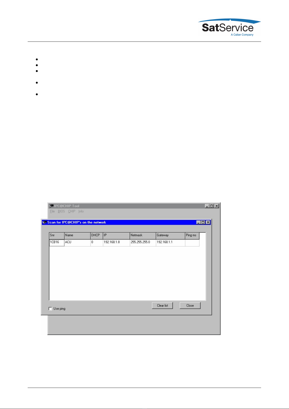
2.2 Setting the IP Address
Before you can operate the power sensor, you need to set the power sensor's IP address. There is a special
configuration program on the documentation CD shipping with the power sensor for this purpose. We
recommend to configure the power sensor's TCP/IP settings before you install the power sensor at it's final
place. To configure the power sensor, the following equipment is required: