Camargue 134 10 15 User manual

Camargue
Wood stove
EN 13240
Model : 134 10 15
Output : 10 kW
Description of the appliance
Installation instructions
Operating instructions
Spare parts
Warranty certificate
Document n°1141-8 ~ 06/11/2006
NLFR EN
Technical manual
to be saved
by the user
or uture re erence
STAUB FONDERIE
SARL with the capital o 6 359 540 +
Head O ice Address
2, rue Saint Gilles
68230 TURCKHEIM
RCS Colmar
SIREN 444 881 953
Address
Administration and manu acturing
BP 73
59660 MERVILLE (FRANCE)
Telephone : 00 333 28 43 43 00
Fax : 00 333 28 43 43 99
Subject to modi ications.

2Technical manual “1141”
Camargue - ref. 134 10 15
FRANCO BELGE congratulates you on your choice.
FRANCO BELGE, guarantees the quality o its appliances and is committed to meet its
customers’ needs.
FRANCO BELGE, which can boast a 80-year experience in the industry o heating devices, uses
state-o -the-art technologies
to design and manu acture its whole range o products.
This document contains instructions on how to install your appliance and make ull use o its
unctions, both or your com ort and sa ety.
Contents
Description of the unit ...................................p.3
Package .................p.3
Specifications ..............p.3
Appliance description . . . . . . . . . . p. 3
Operating principle. . . . . . . . . . . . p. 3
Installation instructions ..................................p.4
Warning to the user ...........p.4
The room .................p.4
Flue ....................p.5
Assembly of flue spigot and blanking plates
......................p.5
Smoke exit at rear . ...........p.5
Smoke exit on the top . . . . . . . . . . p. 6
Chimney connector . . . . . . . . . . . p. 6
Fitting of the handle . . . . . . . . . . . p. 6
Pre-utilisation check . . . . . . . . . . . p. 6
Maintenance of the Chimney . . . . . . p. 6
Instructions for user ....................................p.7
Fuel ....................p.7
Instructions for use with wood .....p.7
Lighting ..................p.7
Re-fuelling ................p.8
Instructions for use with solid fuel . . . p. 8
lighting ..................p.8
Re-fuelling . . . . . . . . . . . . . . . . p. 8
De-ashing . . . . . . . . . . . . . . . . p. 8
Maintenance of the stove . . . . . . . . p. 8
Maintenance of the Chimney . . . . . . p. 8
Recommendations . . . . . . . . . . . . p. 9
Trouble shooting . . . . . ........p.9
Spare parts .........................................p.11

This appliance is meant to burn wood safely.
WARNING
Incorrectly installed, this appliance can be dangerous and possibly cause serious accidents.
We recommend that you engage the services of a professional engineer for its installation
and the regular maintenance requirements
1. Description of the unit
1.1. Package
-1 package : Stove
1.2. Specifications
Model ................. 1341015
Nominal Heat Output ....... kW 9,9
Heated volume ........... m
3380
Chimney draft required.......Pa 12
Hearth dimensions
- Width............... mm 495
- Depth ...............mm 255
- Height ..............mm 200
Logs dimensions
- Length maxi ............cm 45
Ash pan capacity .........litre 3
Weight ................kg 115
Mean flue gas temperature.....C° 356
Flue gas mass flow ........g/s 9,6
Efficiency ..............% 72,4
Coa13%O2............% 0,10
Test fuel mass ...........kg 2,3
Note : The performances indicated result from
tests carried out in accordance with standard
EN13240 with logs of Ø 12 of 40 cm and a draught
of 12 Pa.
1.3. Appliance description
Wood stove, in conformity with EN 13240
•Intermittent burning appliance.
•Detachable flue spigot for rear or top chimney
connection.
•Detachable top for easy handling and cleaning (rear
smoke exit only).
•Front loading door fitted with large refractory glass
panel.
•Side loading door.
•Adjustable air control for controlling the burning rate.
•Large ash-pan.
•Long lasting burning cycle : When the appliance is
loaded with à 4,8 kg of dry rate (primary and secondary
air inlet closed) witha5Padraught, it runs for 7 hours.
1.4. Operating principle
The appliance is designed for operating only with the
door closed.
Heat is mainly diffused by radiation, through the window
and body of the appliance. Combustion occurs on the
grate, with draught entry through the top of the grate,
which assists the combustion of volatile materials
helping to keep the glass clean during normal
operation.
Camargue - ref. 134 10 15 Description of the unit
Technical manual “1141” 3
Figure 1 - Dimensions in mm

2. Installation instructions
2.1. Warning to the user
All the local and national regulations, and in
particular those relating to national and European
standards, must be observed when installing the
appliance.
An incorrectly installed heating appliance can
cause serious accidents (chimney fires, burning of
plastic insulation materials, in partition walls, etc.).
The insulation of both the appliance and the
exhaust gas pipe has to be reinforced and done
according to the Standards and the Building
Regulations for safety reasons.
Failure to respect the mounting instructions leads to
engage the responsibility of the one doing the
installation.
The manufacturer’s responsibility shall be limited to the
supply of the equipment.
2.2. The room
Ventilation :
For satisfactory operation with a natural draught, check
that sufficient air for combustion is available in the
room.
Position of the unit :
For new chimney installations, select a central position
within the building, to provide a good heat distribution
around the building.
The heat distribution towards the other rooms will be
made through the communicating doors. These rooms
must be in negative pressure or must include ventilation
gratings.
Floor and walls :
Make sure that the floor can support the weight of the
appliance, its surroundings and the hood. In the
contrary the floor needs to be reinforced with a concrete
screed to distribute this load.
Make sure there are not combustible or covered with
combustible material.
Otherwise it must necessary to install a
non-combustible protection.
There must be a clearance of at least 150 mm at each
side of the appliance and at the back of the appliance
from a non-combustible wall.
This distance must be extended to a minimum
clearance of 400 mm from any combustible materials.
This measurement may be reduced to a minimum gap
of 50 mm when the non-combustible wall is at least
200 mm thick.
There should ideally be a minimum gap of 400 mm at
the right hand side of the stove, this will ensure the best
possible access to the loading door.
When using a single wall flue pipe, there must be a
clearance (A) of at least three times its diameter (B)
from any combustible materials.
If the appliance has to be located in an opening, this
distance must be extended to a minimum clearance (A)
of 450 mm from the pipe or the stove body to any
combustible materials.
4Technical manual “1141”
Camargue - ref. 134 10 15 Installation instructions
"
#
# !
#
*
)
)
+
Figure 2 - Minimum clearances

Hearth
The appliance must stand on a fireproof hearth.
It is possible to provide a hearth made of non
combusible board/sheet material or tiles at least 12 mm
thick.
Constructional hearths should be constructed of solid
non combustible material at least 125 mm thick
(including the thickness of any non combustible floor
under the hearth).
The hearth must protrude at least 400 mm in front of the
stove and 150 mm each side.
If the hearth is constructed on timber, there must be a
clearance of at least 250 mm from the timber to the top
surface of the hearth.
When using a single wall flue pipe, there must be a
clearance (A) of at least 450 mm from any combustible
materials (timber mantel, girder).
See section J of the Building regulations.
2.3. Flue
The chimney must comply with Current Building
Regulations. If in doubt, consult your Dealer or local
Building Inspector.
Existing flue
-The flue must be in good condition and must provide
sufficient draught.
-The flue must be suitable for the installation of solid
fuel burning appliances and comply with Current
Building Regulations.
-The flue must be clean. It should be swept to remove
soot and dislodge tar deposits.
-The flue must be well insulated. If the flue inner wall
surfaces are cold, a good thermal draw is impossible
causing condensation problems (tar formation etc) to
occur.
-The flue must not be shared with other appliances.
-The chimney must be at least 4.5 m (15 ft high).
-In case of a flat roof or when the roof gradient is lower
than 15°, the stack must be 1,2 m (4 feet) high at least.
-If the chimney has any down draught tendency, due to
its position in relation to nearby obstacles, an
anti-down draught cowl must be installed on the
chimney or the chimney height must be increased.
-If the chimney draught is excessive or irregular, a
draught stabilizer (barometric damper) must be
installed to the connector pipe. It must be visible and
accessible.
Chimney to be built / new flue :
-The flue must not be supported by the stove.
-Consult a chimney specialist for advice on suitable
flue systems for solid fuel appliances.
2.4. Assembly of flue spigot and
blanking plates
For the flue collar (303860), the stove is supplied with a
connection flue spigot with an inner diameter of 125 mm
and an outer diameter of 139 mm.
For the flue collar (303826), the stove is supplied with a
connection flue spigot with an inner diameter of
153 mm.
2.5. Smoke exit at rear
Figure 4
-Check that the blanking plate and the clamp are fixed
to the cast iron top.
-Lift the cast iron top from the stove.
-Remove the internal baffle and the rear heat shield
(# 56 & 27, fig. 8, page 12).
-Fix the sealing rope in the groove and fit the flue
spigot, ensuring there is a good seal.
-Replace the internal baffle and re-fit the cast iron top.
-Remove the cut-out in the rear heat shield and re-fit.
Camargue - ref. 134 10 15 Installation instructions
Technical manual “1141” 5
Figure 3 - Removing blanking plate on rear heat shield
Figure 4 - Smoke exit at rear
A: Blanking
plate
B:Flue collar
C: Clamp
D:Sealing rope
E: Supp of flue
baffle

2.6. Smoke exit on the top
Figure 5
-Remove the supplement of flue baffle.
-Lift the cast iron top from the stove.
-Remove the blanking plate and the clamp.
-Fit the sealing rope in the groove and attach the flue
spigot and the supplementary baffle A using the three
bolts and washers supplied.
-Remove the internal baffle and the rear heat shield.
-Position the sealing rope in the groove on the rear
aperture of the stove and fit the blanking plate and the
clamp.
-Replace the internal baffle, the supplement of flue
baffle and the cast iron top.
2.7. Chimney connector
The connection to flue must be carried out
according to local building regulations.
-The appliance must be installed as close as possible
to the chimney.
-The connector pipe must be approved for installation
with combustion products (either 24 ga. Black painted
or blued steel or 316 grade 20 ga. Stainless steel or 1
mm vitreous enamelled steel).
-Pipe diameter must not be less than the appliance
spigot diameter. If there is no other solution, the
reduction can not be more than one diameter lower
than the flue spigot and be situated as distant as
possible from the flue connection of the appliance.
-The connection can be either vertical or horizontal. For
horizontal connections, avoid right angle bends.
-The join between the connection pipe and the
stovepipe, and the flue, must be leak tight.
-The connection pipe and any draught stabiliser must
have access for cleaning.
-The spigot should be connected to a minimum of 125
mm flue system and in that case the appliance is
capable of burning untreated wood and recommended
solid fuels.
2.8. Fitting of the handle
In order to avoid the damaging of the threading, first put
the handle in operating position then screw it into the
taping of the lock (fig. 6).
2.9. Pre-utilisation check
Check the condition of the filler seals, that the door
closes correctly , that the window is not damaged, that
the smoke passages are not obstructed by pieces of
packaging or removable parts. All removable parts, fuel
retainer, oscillating grate, baffle, must be correctly
installed.
Note : if it acts of a ceramics braid, it is consumable and
thus brought to be changed by the user.
2.10. Maintenance of the Chimney
Very important : In order to avoid any incident
(chimney fire, etc...), maintenance tasks must be
carried out regularly. If the appliance is regularly used,
the chimney should be swept several times per year,
together with the stovepipe connection section.
If the chimney catches fire, you must cut off the flue
draught, close the doors and windows, hatches and
keys, remove the embers from the stove, stop up
the connection hole with wet cloths and call the Fire
Brigade.
DO NOT OPEN THE DOOR OF THE APPLIANCE
(OR AIR INLET) UNDER ANY CIRCUMSTANCES
Chimney condition should be checked at least once per
year by a professional engineer.
6Technical manual “1141”
Camargue - ref. 134 10 15 Installation instructions
Figure 5 - Smoke exit on the top
A: Blanking
plate
B:Flue collar
C: Clamp
D:Sealing rope
E: Supp of flue
baffle
Figure 6 - Fitting the handle

3. Instructions for user
The manufacturer will not be responsible for damages
on parts of the appliance due to the use of prohibited
fuel or due to an alteration of the appliance or its
installation.
Only use replacement parts supplied by the
manufacturer.
All the local and national regulations, and in
particular those relating to national and European
standards, must be observed when installing the
appliance.
Don't run the stove in mild weather with coal ! Under
certain circumstances (e.g. fog and repeated thaw)
the chimney will not draw sufficiently well and thus
be at the origin of asphyxia.
3.1. Fuel
This appliance is not an incinerator.
Recommended fuel : Wood
- Use hard wood logs, which have been cut for at least
two years and stored, under shelter (Humidity < 20 %).
- Hardwood has a higher calorific value per cu metre
(oak, ash, maple, birch, elm, beech, etc.).
- Large logs must be split and cut to a usable length,
before being stored in a sheltered and ventilated place.
Recommended fuel : Solid fuels
Smokeless fuels, including coolite nuts, phurnacite,
ancit and extracite.
Not recommended as fuel :
- “green wood”. Green or damp wood reduces stove
efficiency and soils the glass, the internal walls and the
flue (soot, tar, etc.).
- “used timbers”. Burning treated wood (railway
sleepers, telegraph poles, offcuts of plywood or chip
board, pallets, etc.) quickly clogs the flue ways (soot,
tar, etc.), pollutes the environment (pollution and smell,
etc.) and cause the fire to burn too quickly and
overheat.
“Green wood” and “recovered wood” can eventually
cause a chimney fire.
Prohibited fuel : Homefire and any form of bituminous
coal or petroleum based coke.
3.2. Instructions for use with wood
3.3. Lighting
Figure 7
-Slide the top air control (# B1) to the right. Open the
lower spin wheel (# C1).
-Lay firelighters or rolled up newspapers on the grate
with a reasonable quantity, if necessary, of dry kindling
wood. Place 2 or 3 small logs on top.
-Light the newspaper or firelighters using a long taper
and close the door.
-When the fire is burning fiercely, add further logs of a
diameter up to 10 cms.
-When the stove body is very hot, close the lower spin
wheel.
-The burning rate can now be lowered by moving the
top air control to the left.
Camargue - ref. 134 10 15 Instructions for user
Technical manual “1141” 7
Figure 7 - Operating devices
* *
*
)
+
+ +
+ !
,
A: Door lock
B: Adjustable air control for controlling the
burning rate (secondary air inlet).
B2 - Close
B1 - Open
C: Spin wheel for lighting (primary air inlet).
C2 - Normal working setting
C1 - Open for lighting
C3 - De-ashing (Insert the poker into the
upper hole)
D: Opening the main door

3.4. Re-fuelling
The appliance must function door closed and top
plate correctly set up.
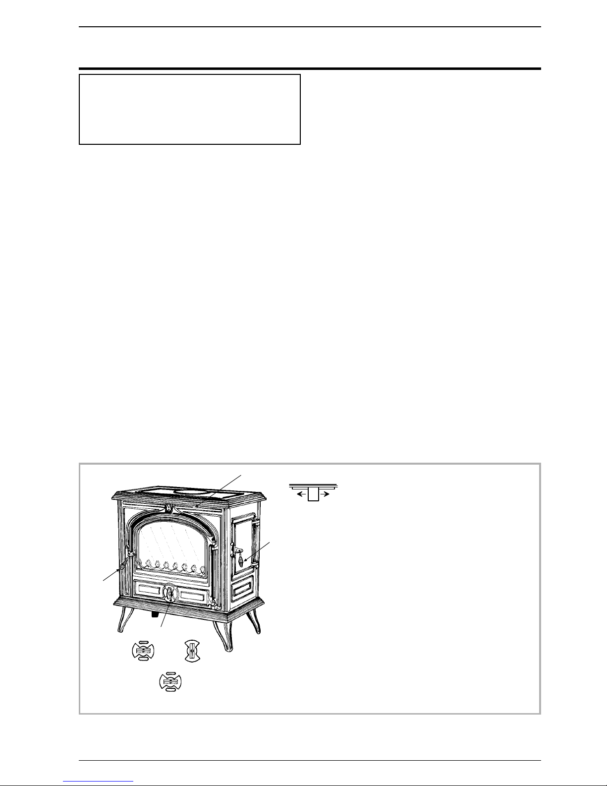
The burning rate can be adjusted by the air control flap
(# B Fig. 7). Experience will show you which settings
are best for your situation. The lighting flap must be
closed (# C2 Fig. 7)
-The airwash system works with the top airslide. When
the top airslide is full open the system works at its
strongest efficiency.
-The more closed down the airslide is, the less effective
the airwash will be ( when shut down completely, the
airwash system can not function )
Loading the fuel :
-It is advisable to wait for the fire to be reduced to hot
embers before re-loading. The door should also be
opened slowly when re-loading.
-The minimum reloading interval for nominal heat
output is 1.5 hours.
-For a briskly burning fire, there should always be at
least two logs in the fire. The fire will burn better if
there are several logs.
-For a slower burning fire (for example, at night), select
larger logs.
-Close the loading door.
Open the lighting flap for a while (# C1 Fig. 7).
3.5. Instructions for use with solid fuel
3.6. lighting
-Slide the top air control (# B1) to the right. Open the
lower spin wheel.
-Lay firelighters or rolled up newspapers on the grate
with a reasonable quantity, if necessary, of dry kindling
wood. Place a small quantity of solid fuel on top.
-Light the newspaper or firelighters using a long taper
and close the door.
-When the fire is burning fiercely, add further fuel.
-When the stove body is hot, close the top air control by
sliding to the left.
-The burning rate can now be adjusted by rotating the
lower spin wheel.
3.7. Re-fuelling
-Open the lower spin wheel.
-Open the glass door and add fuel.
-Leave the lower spin wheel open for a few minutes to
allow the initial volatiles in the fuel to burn.
-Adjust the lower spin wheel to the desired position.
3.8. De-ashing
-Remove ash until glowing ashes start falling into the
pan. (# C3, fig. 7, p. 7)
-Ashes must be removed before loading the firebox
and when the fire doesn’t burn efficiently.
-Ashes must never be allowed to pile up to the grate.
The grate would not be cool down and could rapidly be
damaged.
-Empty the ashes when the appliance is cold,
-Empty the ashes carefully with regard to the live
embers.
REMEMBER TO BURN SOLID FUEL CORRECTLY,
AlR SHOULD BE ALLOWED TO FLOW FROM THE
ASH PIT AREA THROUGH THE GRATE AND
THROUGH THE FUEL. IF THE GRATE OR ASH PAN
ARE CONGESTED, THE PERFOMANCE WILL BE
EFFECTED.
If burning solid fuel, always empty the ash pan at least
once a day or whenever it is full of ashes. Never allow
the ashpan to overfill allowing ash to be in contact with
the underside of the grate. If this condition is allowed,
the grate will wear out pre-maturely.
3.9. Maintenance of the stove
•The appliance must be cleaned regularly , together
with the connecting pipe and the flue pipe.
•Remove all deposits from the combustion chamber
and clean the grate area.
•Cleaning of the glass door can be done with a soft cloth
dampened with water and vinegar or potassium ; this
must be done when the appliance is cold ; then rinse
with clear water. Do not use abrasive cleaners.
•The “vitroceramic” glass will resists to temperatures of
up to 750 C. Should the glass break due to misuse, it
must be replaced by the manufacturers own product.
•All the casing parts can be cleaned using a soft cloth
either dry, or slightly damp. In case of condensation or
water splashes clean the parts before they dry out.
•Check that there are no obstructions before relighting
after a long period of disuse.
•The appliance must not be used with a flue serving
several appliances.
•To maintain the grates ventilation free of any
obstruction.
Warning : The appearance of cracks when burning the
enamelled units is quite usual and tends to disappear
when the appliance is cooling down. It should not be
considered as a defect but rather as a patina of the
enamel which does not affect its quality nor its service
ability.
3.10. Maintenance of the Chimney
Very important : In order to avoid any incident
(chimney fire, etc...), maintenance tasks must be
carried out regularly. If the appliance is regularly used,
the chimney should be swept several times per year,
together with the stovepipe connection section.
If the chimney catches fire, you must cut off the flue
draught, close the doors and windows, hatches and
keys, remove the embers from the stove, stop up
the connection hole with wet cloths and call the Fire
Brigade.
DO NOT OPEN THE DOOR OF THE APPLIANCE
(OR AIR INLET) UNDER ANY CIRCUMSTANCES
Chimney condition should be checked at least once per
year by a professional engineer.
8Technical manual “1141”
Camargue - ref. 134 10 15 Instructions for user

3.11. Recommendations
•The stove may still be hot even when fire has burnt out.
•This room heater is an appliance producing heat and may cause severe burns if touched.
KEEP CHILDREN AWAY.
3.12. Trouble shooting
Situation Probable causes -Corrective action
Fire difficult to start. Fire goes
out.
Wood green… or too damp. -Use hard wood logs, which have been cut for at least
two years and stored, under a ventilated shelter.
Logs are too big. -To light the fire, use small, very dry twigs. To maintain
the fire, use split logs.
Poor quality wood. -Use hardwood that have a higher calorific value per cu
metre (Yoke-elm, oak, ash, maple, birch, elm, beech,
etc.).
Not enough air. -Open air control.
-Open the outside fresh air inlet grid.
Insufficient draught. þ-Check that the flue is not obstructed, sweep it if
necessary.
-Seek advice from a chimney specialist.
Fire burns too quickly. Too much draught. -Partially close the air control.
Excessive draught. þ-Install a draught stabiliser to the connector pipe.
Poor quality wood. -Do not continuously burn small wood, sticks, bundles,
carpentry offcuts (plywood, pallets), etc.
Smokes when lighting up. Flue duct is cold. -Burn paper and kindling wood to increase heat.
Room is in decompression
(negative pressure).
-In houses equipped with mechanical ventilation, partly
open a window until the fire is well established.
Smokes while burning. Insufficient draught. þ-Seek advice from a chimney specialist.
-Check that the flue is not obstructed, sweep it if
necessary
Down draught. þ-Install an anti-down draught cowl.
Room is in decompression
(negative pressure).
þ-In houses equipped with mechanical ventilation, an
outside air intake must be installed for the chimney.
Low heat output. Poor quality wood. -Use the recommended fuel.
Poor mixing of the convection air. -Check the air flow system (air inlet, piping, air outlet).
-Check that the next rooms are equiped with ventilation
grids to help out the hot air circulation.
Camargue - ref. 134 10 15 Instructions for user
Technical manual “1141” 9
þ:This sign means that you should ask
for a qualified engineer to do the work.

10 Technical manual “1141”
Camargue - ref. 134 10 15 Notes
Notes

Technical manual “1141” 11
4. Spare parts
When ordering spare parts, specify the stove type and serial number, including the colour index (on the guarantee
or identification plate), the name of the part and the part number.
Example : Wood stove “Camargue”, ref. 134 10 15, colour Y, Top plate 302141 77
A= 134 10 15 Y B= 134 10 15 L C= 134 10 15 J D= 134 10 15 N E= 134 10 15 Q
Camargue - ref. 134 10 15 Spare parts
1 100956 Axle....................A.....B.....C.....D.....E ......02
2 110405 Hinge pin .......6x35 ......A.....B.....C.....D.....E ......02
4 134749 Pin ...........4x20 ......A.....B.....C.....D.....E ......02
5 181632 Adhesive rope ..............A.....B.....C.....D.....E .....0,80m
6 158541 Handle ..................A.....B.....C.....D.....E ......02
8 162961 Descriptive plate .............A.....B.....C.....D.....E ......01
9 166003 Spring.........11x15 ......A.....B.....C.....D.....E ......01
12 181614 Ceramic rope ....d.9,5mm.....A.....B.....C.....D.....E .....0,87m
13 105006 Ceramic rope .....Ø15 ......A.....B.....C.....D.....E .....3,14m
14 181604 Ceramic rope .....10x4 ......A.....B.....C.....D.....E......1m
15 188779 Ceramic glass ..............A.....B.....C.....D.....E ......01
16 189103 Screw ........27x8x6 ......A.....B.....C.....D.....E ......01
27 205330 Back panel ................A.....B.....C.....D.....E ......01
28 22120066 Striking plate ...............A.....B.....C.....D.....E ......02
29 224022 Ash-pan .................A.....B.....C.....D.....E ......01
32 259015 Fixing plate ................A.....B.....C.....D.....E ......04
33 260537 Heat shield ................A.....B.....C.....D.....E ......01
35 30012159 Right leg .................A................................02
35 30012177 Right leg........................B..........................02
35 30012179 Right leg ..............................C...................02
35 300121EP Right leg ....................................D.............02
35 300121ER Right leg...........................................E ......02
36 30021759 Left leg ..................A................................02
36 30021777 Left leg ........................B..........................02
36 30021779 Left leg...............................C...................02
36 300217EP Left leg .....................................D.............02
36 300217ER Left leg ...........................................E ......02
37 30045560 Base ...................A................................01
37 30045577 Base..........................B..........................01
37 30045579 Base ................................C...................01
37 300455EP Base ......................................D.............01
37 300455ER Base .............................................E ......01
38 30151566 Door lock .................A.....B.....C.....D.....E ......02
39 30174259 Air damper ................A................................01
39 30174277 Air damper ......................B..........................01
39 30174279 Air damper .............................C...................01
39 301742EP Air damper ...................................D.............01
39 301742ER Air damper .........................................E ......01
40 30214159 Top plate .................A................................01
40 30214177 Top plate .......................B..........................01
40 30214179 Top plate..............................C...................01
40 302141EP Top plate ....................................D.............01
40 302141ER Top plate ..........................................E ......01
41 30351059 Loading door ...............A................................01
41 30351077 Loading door .....................B..........................01
41 30351079 Loading door ...........................C...................01
41 303510EP Loading door ..................................D.............01
41 303510ER Loading door ........................................E ......01
42 30371859 Blanking plate ..............A................................01
42 30371877 Blanking plate.....................B..........................01
42 30371879 Blanking plate ...........................C...................01
42 303718EP Blanking plate .................................D.............01
42 303718ER Blanking plate ........................................E ......01
43 30386059 Flue collar ......Ø139......A................................01
43 30386077 Flue collar ......Ø139 ............B..........................01
43 30386079 Flue collar ......Ø139...................C...................01
43 303860EP Flue collar ......Ø139.........................D.............01
N° Code Description......Type ......A.....B.....C.....D.....E......Qty

12 Technical manual “1141”
Camargue - ref. 134 10 15 Spare parts
$ % $ #
$ "
$ !
" '
$ &
%
Figure 8 - Spare parts view

Technical manual “1141” 13
Camargue - ref. 134 10 15 Spare parts
43 303860ER Flue collar ......Ø139 ...............................E ......01
44 305009 Wall....................A.....B.....C.....D.....E ......01
45 305114 Back wall .................A.....B.....C.....D.....E ......01
46 305211 Wall....................A.....B.....C.....D.....E ......01
47 306215 Back wall .................A.....B.....C.....D.....E ......01
48 307416 Fuel retainer ...............A.....B.....C.....D.....E ......01
49 308710 Grate ...................A.....B.....C.....D.....E ......01
50 30985959 Front plate ................A................................01
50 30985977 Front plate ......................B..........................01
50 30985979 Front plate .............................C...................01
50 309859EP Front plate ...................................D.............01
50 309859ER Front plate..........................................E ......01
51 30996459 Main door.................A................................01
51 30996477 Main door .......................B..........................01
51 30996479 Main door .............................C...................01
51 309964EP Main door....................................D.............01
51 309964ER Main door ..........................................E ......01
51 988798 Complete door ..............A................................01
51 988800 Complete door ....................B..........................01
51 988891 Complete door...........................C...................01
51 988858 Complete door .................................D.............01
51 988993 Complete door .......................................E ......01
52 31072159 Right side panel .............A................................01
52 31072177 Right side panel....................B..........................01
52 31072179 Right side panel ..........................C...................01
52 310721EP Right side panel ................................D.............01
52 310721ER Right side panel.......................................E ......01
53 31081159 Left side panel ..............A................................01
53 31081177 Left side panel ....................B..........................01
53 31081179 Left side panel...........................C...................01
53 310811EP Left side panel .................................D.............01
53 310811ER Left side panel .......................................E ......01
54 314607 Inner door ................A.....B.....C.....D.....E ......01
55 319707 Grate support ..............A.....B.....C.....D.....E ......01
56 323211 Flue baffle ................A.....B.....C.....D.....E ......01
57 326601 Supplement of flue baffle ........A.....B.....C.....D.....E ......01
58 41550460 Poker ...................A.....B.....C.....D.....E ......01
60 80800160 Handle ..................A.....B.....C.....D.....E ......01
61 110404 Hinge pin .......6x30 ......A.....B.....C.....D.....E ......02
63 315601 Air duct ..................A.....B.....C.....D.....E ......01
64 442011 Sealing plate ...............A.....B.....C.....D.....E ......01
65 613301 Air control flap ..............A.....B.....C.....D.....E ......01
66 189788 Screw ........M6X30 ......A.....B.....C.....D.....E ......02
67 167322 Washer .........M8.......A.....B.....C.....D.....E ......02
68 142881 Gasket ..................A.....B.....C.....D.....E ......04
69 30382659 Flue collar ......Ø153......A................................01
69 30382677 Flue collar ......Ø153 ............B..........................01
69 30382679 Flue collar ......Ø153...................C...................01
69 303826EP Flue collar ......Ø153.........................D.............01
69 303826ER Flue collar ......Ø153 ...............................E ......01
70 406816 Clamp ..................A.....B.....C.....D.....E ......01
71 134107 Glove ...................A.....B.....C.....D.....E ......01
N° Code Description......Type ......A.....B.....C.....D.....E......Qty
A= 134 10 15 Y B= 134 10 15 L C= 134 10 15 J D= 134 10 15 N E= 134 10 15 Q

§Guarantee certificate §
§Legal guarantee
The specifications, dimensions and information shown
on our documents are provided for information purposes
only and under no circumstances are binding upon the
vendor.
With the aim of constantly improving our equipment, all
modifications considered as necessary by our
departments may be made without notice.
The provisions of the present guarantee certificate are
not excluding or limiting the owner of the equipment’s
rights, concerning the legal guarantee regarding faults or
hidden vices which applies in all circumstances, in the
conditions detailed in articles 1641and following of the
civil code, and in the country in which the equipment was
purchased.
§Contractual guarantee
Our equipment is guaranteed against faults and hidden
vices subject to the following conditions:
1) Installation and adjustment of the device by a professional
installer.
2) Observance of the instructions provided in our technical
documents and our installation/adjustment instructions.
3) The installation, use and maintenance of the device carried
out in conformity with the applicable standards and
legislation, and with the indications provided in the technical
instructions accompanying the device.
This guarantee covers the replacement, in our factory, of
parts recognised as being defective from the outset by
our “Guarantee Inspection” Department. Carriage and
labour is at the user’s cost. Moreover, if the repair or
replacement of parts covered by the guarantee is found
to be too costly vis-à-vis the price of the appliance, the
decision to replace or repair the appliance will be taken
by the vendor.
Our guarantee is for 2 (two) years for all appliances, with
the exception of closed combustion fireplace and inserts
for which our guarantee is 5 (five) years excluding the
following:
1) Indicator lights, fuses, electrical elements and fans.
2) Parts subject to wear or in contact with high temperatures
namely: soles and burner grills, bottom plates baffles, ash
pans, paintwork and surface treatments for decorative
parts. Also excluded from this guarantee are seals and
windows.
3) Any damage which may result from the use of the appliance
with a fuel other than that stipulated in our instructions.
4) Damage occurring to parts caused by elements outside the
appliance (down draught, storm damage, damp, abnormal
pressure or vacuum, heat shocks, etc.).
5) Damage to electrical parts caused by plugging in and using
the appliance on a mains system, the voltage of which
(measured at the entrance to the appliance) is 10% above
or below the nominal voltage of 220 V.
§Exclusion of liability
In the case of a product manufactured at the client’s
request, under no circumstances may we, as a
subcontractor, be considered liable vis-a-vis the client or
third parties for defects arising from the installation or a
design fault with the item in question.
*Name and address of the installer : _____________________________
______________________________________________
(Telephone : _______________________________________
*Name and address of the customer : _____________________________
______________________________________________
Date of installation : __ __ / __ __ /__ __ __ __
Model of the appliance : q134 10 15
Color : qYqJqLqNqQ
Serial number : ___ ___ ___ ___ ___ ___
• This certificate has to be completed and kept carefully.
In case of claims, send a copy of this to :
STAUB FONDERIE, BP 73, 59660 MERVILLE, FRANCE.
Table of contents
Popular Wood Stove manuals by other brands

Elmira Stove Works
Elmira Stove Works 1842-G Installation & operating instructions

Henley
Henley Achill 17.1kW user manual

Osburn
Osburn 900 Installation and operation manual

RIKA
RIKA induo II operating manual

RAIS
RAIS 800 Instructions for installation, use and maintenance

JOSEF DAVIDSSONS
JOSEF DAVIDSSONS Royal Viking Installation and maintenance manual

Lopi
Lopi Cape Cod Wood Stove owner's manual

Plamen
Plamen Authentic 50 Technical manual

Quadra-Fire
Quadra-Fire DISCOVERY I Series owner's manual

Regency Fireplace Products
Regency Fireplace Products Alterra F175B-2 Owners & installation manual

RAIS
RAIS VIVA L user manual

Vogelzang International
Vogelzang International VG180L Owner's operation and instruction manual