CAMERA LINK FS5000HECL User manual

M08627;1/39
- 1 -
Video Camera
Instruction Manual
5 Mega pixel Progressive Scan Color Camera
FS5000HECL
●We greatly appreciate your confidence choosing our TAKEX CCD Video Camera.
●Please read this manual and the attached guarantee certificate carefully and manage the camera properly.
Keep this manual at hand and reread it whenever you are uncertain about the operation.
Table of Contents
1. Features ………………………………………………… 3
2. Outline ………………………………………………… 3
3. Description of each component ………………………………………………… 4
4. How to operate ………………………………………………… 6
5. Various settings ………………………………………………… 13
6. How to change settings ………………………………………………… 17
7. Serial communication control ………………………………………………… 27
8. Timing chart ………………………………………………… 32
9. Note …………………………………………………38
10. Specifications ………………………………………………… 39
11. Dimensions ………………………………………………… 39
TAKENAKA SYSTEM CO., LTD.
Document No. M08627
FS5000HECL Instruction Manual (8
th
Version)

M08627;2/39
- 2 -
[Revision history]
Version Revised contents Articles Date Document No.
Remarks
1
1
st
version -- Initial version 2005-12-16
M05C16
2
2
nd
version Error correction Correction of frame rate 2006-03-01
M06301
3
3
rd
version Correction of terminology Add Draft scan on table(5-2) 2006-05-24
M06524
4
4
th
version Error correction Correction of low speed shutter
time (table 6-1). 2006-05-30
M06530
5
5
th
version
The modification associated with
the design change of the front-end
Change of the number of fixing
holes at front-end. 2007-03-15
M07315
6
6
th
version
Error correction
Correction of serial communication
stop bit length (section 7) 2007-06-18
M07618A
7
7
th
version
Error correction
Correction of outside dimensions 2008-04-17
M08417A
8
8
th
version
Error correction Correction of Pin layout table(3-2)
2008-06-27
M08627
Description of special remarks used in this manual
(Note)················Particulars which require the user’s attention are explained.
(!)················Particulars which require the user’s close attention in terms of comparison with the conventional
products are explained.
[Terminology]················Terms specifically defined for the purpose of describing the operation of this camera are explained.
[Explanation]················Particulars for which details may be needed for user’s understanding of the operation of this
camera are explained.

M08627;3/39
- 3 -
1. Features
●
FS5000HECL is a full frame shutter camera incorporated with 5 megapixel, 2/3”-size CCD image sensor.
●
High resolution full frame color image can be obtained when used in combination with the capture board which has color
conversion function (Bayer to RGB).
●
A full frame shutter image can be obtained at a rate of 5 frames per second.
●
10 bit (or 8bit/selectable) digital image signal output complying with Camera Link (Base Configuration).
●
The internally set values of the camera can be externally controlled with serial communication via Camera Link.
●
The character information of the current setting status of the camera can be superimposed over the captured image on
the screen. (On Screen Display function)
●
The monitoring function for measuring the internal temperature of the camera.
●
The asynchronous shutter is applicable in the existing preset shutter mode and the pulse width control mode and
additionally in the double pulse mode.
●
The camera is designed so that the strobe signal can be output even in the continuous shutter mode, and this
contributes to the power saving for LED lighting and others as well as the reduction of smear.
●
The ID information set by the user for each camera can be saved and read out whenever necessary (via serial
communication link).
2. Outline
Image sensor Progressive scanning, interline
OB(Optical Black)
Effective image pickup area
V
2616
8
2
1960
H
12
40
2/3 inch
Number of effective pixels 5 megapixels
Read out
scanning
Horizontal 10.30 KHz
Vertical 5 Hz
Clock 32.50 MHz
Electronic shutter 1/10000 ~ 1/5 second
(Continuous shutter / Asynchronous shutter)
Video output signal Digital 10bit
Complied with Camera Link (Base Configuration)
Scanning mode Normal scanning for all pixels (5 fps)
Partial scanning for central part (10 fps)
Draft scanning (35.7 fps)
Gb
B Gb
B
R Gr R Gr
Gb
B Gb
B
R Gr R Gr
Block chart of this equipment
Color coding
The Bayer color filter array is adopted for a RGB
primary color filter arrangement.(See right figure.)
Gb or Gr in the right figure represents Green filter on
the same line as Blue filter or Red filter respectively.
Horizontal direction
Vertical direction

M08627;4/39
- 4 -
3. Description of Each Component
(3-1) Description of rear panel of camera
Panel to set up operation mode, electronic shutter speed and other
parameters and to connect each output connector
(3-2) Camera connector (HRS HR10A-10R-12PB)
The pin arrangement of the camera cable connector (12 pins) and
the signals assigned to those pins are shown in the following table:
1
0
1
1
1
2
9
8
7
6
5
4
3
2
1
(Pin arrangement viewed from the outside of the
camera)
Pin No. Signal name Description I/O
1 GND (0V) Power ground
2 +12VDC DC power input (In)
3 (AGND) *1
Analog signal ground
4 NC *2
No contact
5 GND Signal ground
6 Vinit1 Input for external trigger In
7 Ext-VD Input for external VD In
8 GND Signal ground
9 Ext-HD Input for external HD In
10 GND Signal ground
11 STRB Strobe signal output Out
12 GND Signal ground
*1 (AGND) is Analog signal ground. Do not assign any signals for this camera.
*2 Normally, Do not assign any signals to the NC pins .
(3-3) Camera Link connector (3M / MDR-26 FEMALE)
The pin arrangement and the signals assigned to those pins are shown in the following table:
[Pin arrangement of Camera Link connector (MDR-26 Connector)]
Pin No.
Signal name Twin-ax cable
assignment Pin No.
Signal name
Twin-ax cable
assignment
1 inner shield shield 14 inner shield shield
2 X0- PAIR1- 15 X0+ PAIR1+
3 X1- PAIR2- 16 X1+ PAIR2+
4 X2- PAIR3- 17 X2+ PAIR3+
5 Xclk- PAIR4- 18 Xclk+ PAIR4+
6 X3- PAIR5- 19 X3+ PAIR5+
7 SerTC+ PAIR6+ 20 SerTC- PAIR6-
8 SerTFG- PAIR7- 21 SerTFG+ PAIR7+
9 CC1- PAIR8- 22 CC1+ PAIR8+
10 CC2+ PAIR9+ 23 CC2- PAIR9-
11 CC3- PAIR10- 24 CC3+ PAIR10+
12 CC4+ PAIR11+ 25 CC4- PAIR11-
13 inner shield shield 26 inner shield shield
2
6
1
3
1
4
1
Camera Link
External view of Camera Link
connector
(Viewed from the outside of the
camera)
(Note) The pins of Camera Link connector are differently laid out for the
camera (upper table) and for the capture board.
Note that the connection numbers of the cable for the capture board
are opposite to those for the camera as described below:
1 = inner shield, 14 = inner shield
2 = CC4-, 15 = CC4+
3 = CC3+, 16 = CC3-
⋅⋅⋅⋅ ⋅⋅⋅
12 = X0+, 25 = X0-
13 = inner shield, 26 = inner shield
(Pin layout on frame grabber board side)
POWER
D
U
E
XP.
Camera Link
MODE
Camera link
connector
Mode switch
Operation
indicator(LED)
UP/DOWN switch
Camera connector
(12 pin)
Shutter switch

M08627;5/39
- 5 -
[Table of Camera Link bit assignment] (showing correspondence relation between before and after encoding)
Camera Link port
(Node name) Camera signal
name I/O
Remark
Strobe CLK O Pixel clock
LVAL LDV O Horizontal synchronous timing
FVAL FDV O Vertical synchronous timing
DVAL - O (Fixed to H level)
Spare - O (Fixed to H level)
PORTA0 D0 / (D2)
O Lowermost data
PORTA1 D1 / (D3)
O
PORTA2 D2 / (D4)
O
PORTA3 D3 / (D5)
O
PORTA4 D4 / (D6)
O
PORTA5 D5 / (D7)
O
PORTA6 D6 / (D8)
O
PORTA7 D7 / (D9)
O
PORTB0 D8 / (L) O
PORTB1 D9 / (L) O Uppermost data
PORTB2, 3, 6, 7 L O (Fixed to L level)
PORTC0 ~7 L O (Fixed to L level)
CC1 Vinit2 I Asynchronous shutter trigger
CC2 (reserved) I (Reserved for future products)
CC3 (reserved) I (Reserved for future products)
CC4 (reserved) I (Reserved for future products)
SerTFG TXD O URAT transmission data (Same timing as conventional RS-232C)
SerTC RXD I URAT reception data (Same timing as conventional RS-232C)
* The port assignment is in conformity to “Base Configuration”, the standard of Camera Link.
* 8 or 10 bit digital image signal output complying with Camera Link STD (Base Configuration) can be obtained.
* Indicators in parenthesis corresponding to camera signal name PORTA(0) to PORTA(7), PORTB(0) to PORTB(1) are bit
assignment for 8 bit output. The factory default is 10 bit format (10 bit×1) for image signal data.
Fixing screw × 2
Twin-Ax cable
MDR-26 Twin-Ax cable harness (male)
MDR
-
26 Twin
-
Ax
cable harness (male)
Fixing screw × 2
External view of Camera Link cable assembly

M08627;6/39
- 6 -
4. How to Operate
(4-1) Connection method
●Connection
Refer to the connection example between the camera and peripheral devices (Fig. 4-1).
(1) Remove the cover of the lens attachment section
and attach a lens (option).
(2) Connect the camera head to a power supply unit
(option) with a camera cable (option).
The maximum allowable length of a camera cable
is 25 m.
(3) Set the camera operation modes in accordance
with the setting instructions for the operation
modes and the shutter speed that are described
in another section.
(4) Connect the digital output connectors on the rear
panel of the camera to the input terminals of the
image processing units (frame grabber board,
computer, etc.) with digital cables (option)
conforming to Camera Link STD. The maximum
allowable length between the digital output
connector of the camera and the input terminal of
said image processing unit is 10m.
(5) Confirm the connecting condition before turning on the power switch of the camera.
In 1 or 2 seconds after the power is turned on, the LED operation indicator on the rear panel of the camera changes
from orange to green to show that the camera is in operation.
(Note) It is required that the capture board should have the color conversion function (Bayer to RGB conversion) to obtain
color images by this camera.
(Note) The maximum allowable lengths of the camera cable and the digital cable aforementioned are not for the purpose
of guaranteeing the operation of the camera. Proper image signals may not be obtained even when the cables are
within the allowable ranges, depending on the installation conditions of the camera, cables in use and others.
[Important]
(Note) Make sure to turn off the power switch of the camera before connecting or disconnecting the camera cable.
If the cable is connected or disconnected while the power is supplied, troubles may be caused.
(Note) Make sure to turn off the camera and connected devices in advance when the camera is connected.
(Note) When a power supply unit other than Takenaka’s product that are separately sold is used, make sure that it
complies with the following rated specifications:
Power supply voltage: DC12V±10%
Current capacity: 500mA or over
Take into consideration the fact that inrush current of about 1A flows in when power is applied.
Ripple voltage: 50mVp-p or less (recommended value)
Connector: 12 pin connector 1 pin (GND), 2 pins (+12VDC)
(Note) Some power supply units other than TAKENAKA’s products have different layout of power connection pins. Make
sure to check the compatibility of the power supply unit and the camera connection pins in advance.
Carefully note that any failure associated with power application to out-of-specification pins and others is subject to
charged repair.
P O
W E
R
O
N
L
O
C
K
C
Y
C
L
D
I
R
E
C
T
T
R
I
G
P
U
1
0
0
P
O
W
E
R
U
N
I
T
TRIG
F
C
-
C
A
M
PU100
(or PU-97)
FC Camera
Camera Link cable
Pulse generating
circuit
(sensor and others)
12W-02 or
others
Computer
Capture board
(Camera Link)
Fig. 4-1 Connection example between camera
and peripheral devices

M08627;7/39
- 7 -
(4-2) Input of Vinit signal (asynchronous trigger signal)
●How to input Vinit signal
If the camera is used in the asynchronous shutter mode, the Vinit signal (asynchronous trigger signal) must be input
from the user side unit.
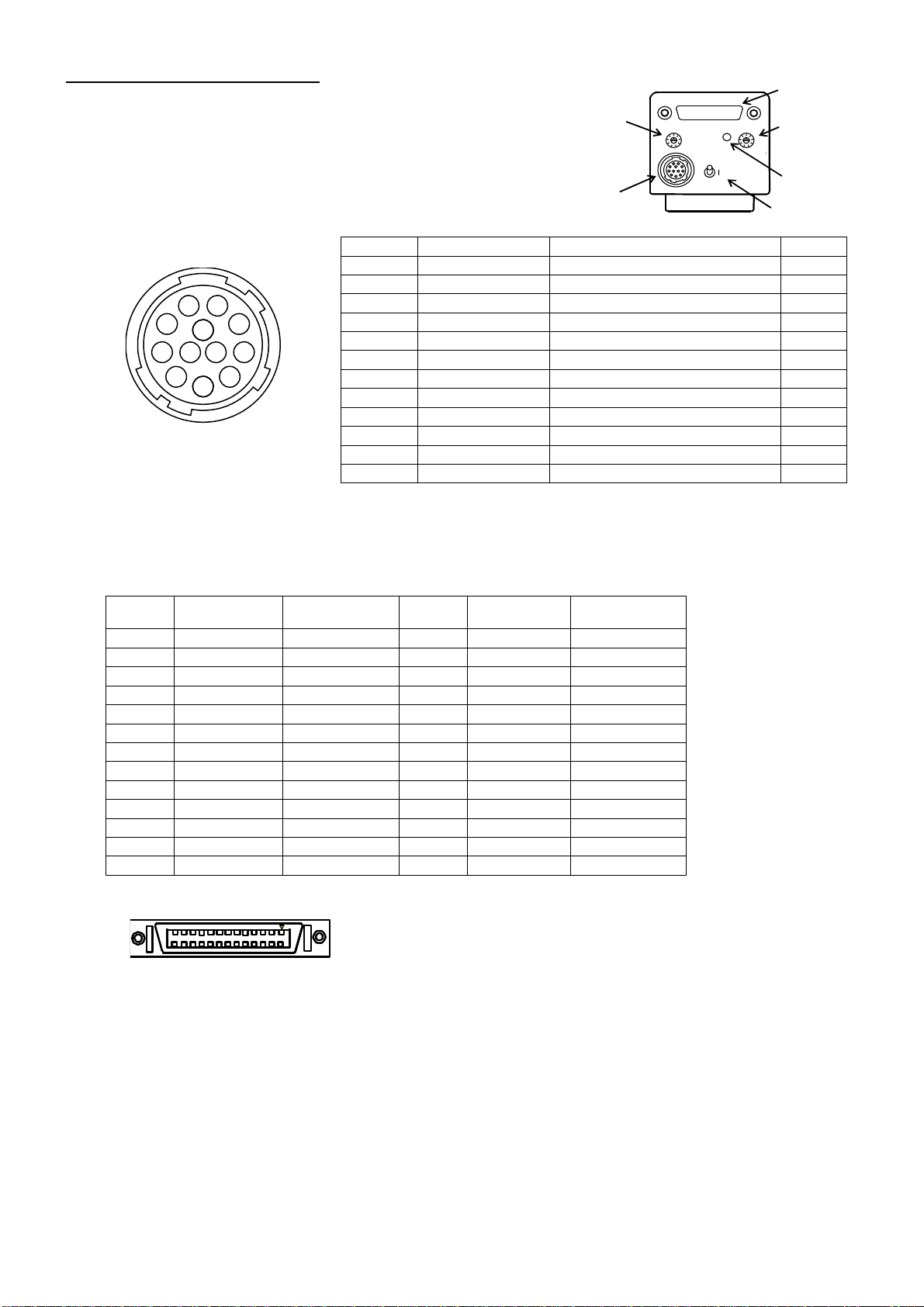
The Vinit signal is input from Pin (6) of the “POWER” connector (12 pin connector) on the rear of the camera, or is
input as the CC1 signal from the “Camera Link” connector.
If the camera is connected to the power supply unit, PU100 (or PU-97), with a cable of Takenaka’s 12W series,
connect the Vinit signal (asynchronous trigger signal) to the trigger input terminal (“EXT” BNC for PU-97) of the power
supply unit (PU100).
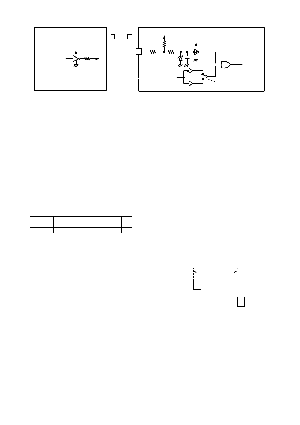
(Note) OR operation (negative OR) is implemented inside the camera between Vinit1 input signal from Pin (6) of “POWER”
connector and Vinit2 input signal as CC1 signal of “Camera Link” connector (see the figure below).
(Note) If either one of those are fixed to the L level (active state),
the Vinit signal (logical sum) is also fixed to the L level and
the trailing edge signal cannot be obtained. This would
result in failure in starting up the asynchronous shutter
operation. Make sure to fix the input signal on the unused
side to the H level, to keep it at high impedance level or
open state (no connection).
●LED Vinit signal monitor indicator
When this camera is set in the asynchronous shutter mode, the LED
indicator on the rear panel of the camera lights up in red for one shot in
response to the input of the external trigger signal (Vinit signal).
This allows the user to confirm the state of signal input.
The red LED lights up for a certain period of time (about 100 ms) on
each trailing edge of the trigger input pulse. If a next trigger signal is
input within this period, the lighting time of the LED will be retriggered
and extended.
Since the lighting of the LED responses only to the trailing edge of the
trigger input, it lights up only once for 100 ms even if the trigger input
pulse duration is longer than the one shot time of period.
●Setting of various asynchronous shutter modes
Set the parameters and others in accordance with the following table:
Table 4-1 Setting of various asynchronous shutter modes
Asynchronous shutter mode 2 TRIG PWC Shutter switch
Remark
Preset shutter (PWC=DISABLED)
DISABLED
DISABLED
1 to 9
Preset shutter (PWC=ENABLED)
ENABLED
1 to 8
Pulse width control 9 Shutter switch = 1 to 8: same as preset shutter
2 TRIG (Double pulse) ENABLED 9 Shutter switch = 1 to 8: same as preset shutter
(NOTE↓)
(Note) When shutter switch is 0, “Continuous image output(without shutter)” is applied for the all.
(Note) For setting methods for the respective parameters of “PWC” and others
→
See “(6-3) How to set operation mode”.
(Note) When it is set to “2 TRIG=ENABLED” and ”PWC=ENABLED” and the shutter switch is positioned from 2 to 8 , only if the
trigger pulse is input in the order of “TRG-A”
→
”TRIG-B” at a time lag longer than 1 horizontal synchronous interval, preset
shutter operation starting at trailing edge of “TRIG-A” is initiated.
●Recommended timing of asynchronous shutter
trigger signal (Vinit signal) for preset shutter/pulse width control
For the case of preset shutter mode
, the negative logic pulse
is applied within the width range from 1
H (1 horizontal
synchronous interval) to 1 msec as described below.
For this
case, the exposure operation starts in synchronization
with
the HD(horizontal synchronous signal)
trailing edge inside
the camera after and closest to the trailing edge timing of
the
applied pulse.
For the case of the pulse width control exposure mode,
numeric value of
the L level interval of the input Vinit pulse
(shown as Tvinit in the figure) is retrieved
in synchronization
with the HD
trailing edge inside the camera, and the in
teger
multiple number of H (1 horizontal synchronous interval
) that is
closest to the retrieved Vinit pulse duration
is transmitted as
nH to the inside of the camera. Then the shutter speed
is
determined in response to the time nH.
Vinit
Tvinit
[For the case of preset shutter mode]
1H(100
µ
s)
≤
Tvinit
≤
1ms
(The shutter speed is independent of the Vinit width.)
[For the case of pulse width control mode]
(Where PWC=ENABLED, shutter switch = 9)
nH
≤
Tvinit <(n+1)H (n is 1 or larger integer.)
(This is the pulse width where shutter exposure time =nH)
Fig. 4-3 Recommended Vinit signal timing waveform
(Note) In the pulse width control, the shutter exposure time is almost equal to the integral multiple number of the horizontal
synchronous time (H) that is closest to the Vinit pulse duration. More specifically, however, the shutter exposure time is
indefinite for the time period corresponding to 1H width in the case of normal external trigger input (or the case where the
Vinit signal is not in synchronization with the horizontal synchronous timing of the camera)
→
Refer to the timing chart
described in another section for the details.
(Note) When the shutter exposure time is too long in the pulse width control mode, the S/N ratio of the image will be degraded due
to the reduction of dynamic range of CCD, accumulation of thermal noise components of CCD image sensor in proportion
to the shutter speed and other factors. Therefore, if a long exposure time is employed, it is recommended to conduct
experiments using realistic exposure times in actual conditions to check for the appropriateness.
POWER
D
U
E
XP.
Camera Link
MODE
LED operation
indicator
Red LED lights up in response to trigger
signal input (Vinit).
"
CC1
”
(Vinit 2)
H
"
POWER
”
-
6 (Vinit
1
)
Internal
circuit
Fig. 4-2 Internal connection of Vinit signals
FC2000CL camera

M08627;8/39
- 8 -
●Example of drive circuit for Vinit1 input circuit
75
Ω
6
Vinit1 IN
VCC
3.3V
4.7k
47p
3.3V
10k
100Ω
NORMAL
INVERTED
3.9 ZD
* The Vinit signal should not include unnecessary
noise components such as chattering.
●Polarity reversal of Vinit2 input
The input polarity of the trigger signal (Vinit2) to be applied via CC1 of Camera Link can be inverted.
Some capture boards may have the polarity of the trigger signal input from CC1 that is fixed to positive logic (L level at
normal/H level at active), which is not compatible with the trigger signal of negative logic input (factory preset polarity
of this equipment). In this case, the input polarity of the trigger signal (Vinit2) via CC1 can be inverted to change from
negative to positive logic by the setting of the camera.
→Refer to “(6-3) How to set operation mode” for the specific setting method.
(Note) The setting of the polarity reversal is valid only for Vinit2. The input polarity of Vinit1 is always negative logic
regardless of this setting.
(4-3) Asynchronous shutter / Double pulse mode
The camera can operate in double pulse mode (2-triger mode) which controls shutter exposure time by the time interval of
two input pulses, applying independent dual negative logic pulses as trigger signals.
●Trigger input pins
The pin arrangement of trigger input pins (in Camera connector) are shown in the table below.
(Camera connector) Double pulse mode input pins
Pin No. Signal name
Description I/o
7 TRIG-A Trigger input A
In
9 TRiG-B Trigger input B
in
(Note) Normal trigger inputs (Vint1,Vint2) for asynchronous shutter operation are not used. Keep it open state or H level.
●External sync operation by HD/VD.
External sync operation by HD/VD signal is not available in double pulse mode, as each input pins used for Ext-VD and
Ext-HD at normal setting are used for trigger signal input.
●Setting for double pulse mode
Set it in accordance with the table 4-1” Setting of
various asynchronous shutter modes”.
●Recommending timing for double pulse trigger signal
The negative logic pulse is applied to TRIG-A,TRIG-B
input pins within the width range from 1 H (1 horizontal
synchronous interval) to 1ms, as shown in right figure.
●Level of input signal
Sync input signal level is 2 to 5 V p-p (within the level
range from -0.5V to 5V ), in contact state to
TRIG-A,TRIG-B input pins.
74AC04 or
others
Inside of camera
TC74LVX14
(or equivalent)
To internal circuit
Setting of Vinit2 polarity
CC1 (Vinit2) input
Camera
connector
VCC is +5V or +3V
[Example of user circuit]
TRIG-A
Ts
1H
≦
Ta,Tb
≦
1ms
(Shutterexposure time is independent of these pulse duration.)
[Shutterexposure time
in
Double pulse mode ]
nH
≦
Ts
<
(n+1)H (n is 1orlarger integer)
(This is the time differencewhereshutterexposure time =nH)
TRIG-B
Ta
Tb
[Ta,Tb]

M08627;9/39
- 9 -
(4-4) Input of external synchronous trigger signal(Ext-HD/VD)
●How to input external synchronous trigger signal
When more than one cameras are used in synchronization state, it is necessary to input external synchronous signal
(Ext-HD/VD signal) from user side equipment. When it is needed to synchronize horizontal timing, input HD signal.
Input HD and VD signals to synchronize both horizontal and vertical timings.
(Note) Note that the delay jitter may occur between externally supplied HD signal and HD signal within the camera, when
horizontal operation timing is synchronized by external synchronous signal,
(Note) When in asynchronous mode, only the HD signal is effective as an external sync signal. In that case, VD signal is
neglected. Normally, do not apply VD external sync signal in asynchronous shutter mode.
●Recommended external sync signal
HD
VD
Th
Tlh
Tlv
※
Tv
Parameter
Scan mode Th Tv Tlh Tlv VD
↓
/ HD
↓
phase error
Normal scan mode 97.11
µ
s ±1 % 2056 × Th 0.1 × Th ±10 % 9 × Th 0 ±1.0
µ
s
Partial scan mode
↑
1028 × Th
↑
↑
↑
Draft scan mode 112.37
µ
s ±1 % 249 × Th
↑
↑
↑
[Important]
(Note) Make sure to follow the conditions of “Recommended external sinc signal”.
If the signals of incorrect timing or
incorrect level are input, troubles may be caused.
(Note) When the camera is used in the asynchronous shutter mode
/ double pulse mode, set the camera operation mode
to double pulse mode (“2 TRIG-ENABLED”) before the trigger signal is input to TRIG-A,TRIG-
B. If the trigger signal
is input before the camera is set to double pulse mode, the camera may malfunctions
as if external sync signal is
applied at abnormal timing.
●Example of external sync input circuit and drive circuit
Camera
connector
Inside thecamera
To internal circuit
10 K
T r
1 0K
4.7K
3.3V 3.3V
22µF
2 2 0
O
1 00pF
7 5Ω
Example of usercircuit
74AC04 or
others
VCC
Vccis
+
5V or
+
3V
※
The Vint signal should not include unnecessary
noisecomponents such as chattering.
Ext-VD 7
Ext-HD 9
(4-5) Other input/output circuit
●Strobe signal output circuit
The internal output circuit is shown in the
right figure.
(4-6) Strobe signal in continuous shutter mode
Although conventional cameras output the strobe signal (STRB) only in the asynchronous shutter mode, this equipment is
capable of outputting the strobe signal even in the continuous shutter mode by changing the settings.
The default setting is OFF (no strobe signal in continuous shutter mode). This setting can be changed on the configuration
menu (Operation Mode Setting Group C) or by way of rewriting the configuration register with serial communication
commands.
+
5
V
100
6.8V.ZD
Strobe signal: Pin 11 of
camera connector
From internal
circuit
74VHCT04A
(or equivalent)

M08627;10/39
- 10 -
[Explanation] Use of strobe signal in continuous shutter mode
In the continuous shutter mode, only the incoming light for the time matching the exposure time of the camera is valid.
Accordingly, when a lighting unit is used in the continuous lighting mode, the lighting in any time other than this exposure time
period would be wasted.
Since this equipment is capable of outputting strobe signal (STRB) even in the continuous shutter mode, this output is used as a
trigger to control a LED light or other lighting units that can be turned on or off, which helps eliminating the lighting during the
useless lighting time.
The following benefits are derived from this type of lighting control:
●
The consumption of the power to a light can be saved by way of lighting only during the valid time for exposure.
●
The occurrence of smear is reduced because no light enters any time other than the exposure time periods.
(Note) When the strobe signal is used in the continuous shutter mode to make ON/OFF control on a lighting source unit,
the following must be taken into consideration:
Wherever possible, use a strobe lighting unit or others that are equipped with a power source separated from that
of the camera (electrically isolated power source) and a trigger input terminal (photo coupler input, etc.). If a
lighting unit that shares a power source or a ground circuit with the camera is turned on or off by the strobe signal,
the image output from the camera may have noise due to the influence of the fluctuation of the power supply
voltage or change in the electric potential that occurs at the ON/OFF timing.
Even when the insulation aforementioned is applied, the electromagnetic induction may lead to the occurrence of
noise on the image signal if the electric current of the lighting unit to be control is large. In this case, a measure
must be introduced to reduce electromagnetic induction noise arising from the lighting unit.
(4-7) Test pattern display function
When initially connecting this camera to an image capture board, the
use of the test pattern display function of the equipment makes it easier
to confirm that the output timing of the camera and the details of the
signal connection match the particulars of the capture board.
When the test pattern function is set to be ON, the image sensor
outputs not pictures but the test pattern as shown on the right.
As for this pattern, a numerical value of 4 is simply added in an
incremental manner for every horizontal pixel, and a saw-tooth profile is
shown in the range from the numerical value of 0 to 1020.
(when set at 10bit gray scale) (Lower part of the right figure)
(Note) In this camera, Bayer array RGB signal is normally output, but
output signal is of B/W when this test pattern function is used.
(Note) In the higher-order 8 bits out of 10 bits data, a numerical value of
1 is incrementally added for every horizontal pixel in the range of
0 to 255 for the case of 8 bits output.
And it’s in the range of 0 to 1020 for the case of 10bits output, as
lower-order 2 bits of 10 bits data are fixed to zero.
(Note) The value does not start with 0 at the edge of the effective image area.
(Note) The output values of the test pattern are not affected by the values of the gain setting or offset setting of the
camera.
The default setting is OFF. This setting can be changed on the configuration menu (Operation Mode Setting Group D) or
by way of rewriting the configuration register with serial communication commands.
(4-8) Monitoring function for internal temperature of camera
This camera is equipped with an internal temperature sensor to monitor the temperature inside the body. This function
makes it possible to use the camera in a safer way even in a harsh environment in terms of temperature, for example use
in the open air. With the use of serial communication commands, this function also works to control the forced air-cooling
fan of the camera and peripheral devices and others.
●How to monitor internal temperature of camera
The following two methods are available for monitoring the internal temperature of the camera:
●Turn on the MENU display and confirm it by the OSD over the image. (Temperature to be displayed in Celsius)
●Confirm it by temperature data to be returned in response to the RS-232C command (”RTMP” command).
(Numerical conversion required separately)
Shutter exposure time
Continuous lighting
STRB signal
Exposure
Exposure
Valid Useless lighting time
0
1020

M08627;11/39
- 11 -
(Note) Carefully note that the temperature data obtained by this monitoring function is not for the ambient temperature but
the internal temperature of the camera. As a general rule, the internal temperature of the camera is higher than the
ambient temperature because of the heat generation associated with the consumed electric power inside the
camera.
Even when the temperature monitored by this function exceeds the value of the “Operation ambient temperature”
shown in the specifications of the camera, no operational trouble will be caused as long as the ambient
temperature is equal to the one of the specifications or lower, and sufficient countermeasures against temperature
are taken.
●Detection performance for temperature data
Temperature resolution : 0.5°
Update interval of data : 0.4 sec.
Temperature detection accuracy: ±2°C (-40°C to +85° C), +3 to -2°C (55°C to 125°C)
Effective data range : -55°C to 125°C (as long as t he operation ambient temperature of the camera is
within the range defined by the specifications.)
●Temperature data by RS-232C communication
The temperature data to be returned in response to the “RTMP” command of RS-232C is generated in the following
format:
[Data format]
The lower 10 bits out of the 16 bits of the returned data are valid.
XXXXXD9D8…D0 (invalid upper 6 bits/valid lower 10 bits as the data)
Db=B’D9D8…D0 in the binary system shows a signed integer value in two’s complement form.
However, the effective range of the temperature data is limited to the following due to the operational restriction of the
temperature sensor:
Effective range of temperature data: -110 (-55°C) to +250 (125°C)
(Note) The accuracy of the values of the temperature data is not guaranteed when the operation ambient temperature is
not within the range defined by the specifications.
[Conversion method from retuned data to temperature in Celsius]
The temperature in Celsius is computed as Tc from the following formula where Dt is the signed integer number converted
from the above described 10 bit binary value of “Db=B’D9D8…D0”:
Internal temperature of camera: Tc=Dt×0.5°C
(Example 1) Where Td, the returned value of the temperature data, is “H’0032” in the hexadecimal system, it is
expressed in the binary system as follows:
Td=H’0032=B’0000.0000.0011.0010
∴Db=B’00.0011.0010 =+50 (Only upper 10 digits of Td are valid.)
Then, Tc is calculated from the following formula: Tc=+50×0.5°C=+25°C
(Example 2) Where Td, the returned value of the temperature data, is “H’03FA” in the hexadecimal system, it is
expressed in the binary system as follows:
Td=H’03F1=B’0000.0011.1111.1010
∴Db=B’11.1111.1010 (Only upper 10 digits of Td are valid.) →Dt=-6 (↓Refer to [Explanation])
Then, Tc is calculated from the following formula: Tc=Dt×0.5°C=-6×0.5°C=-3°C
[Explanation] Example of conversion algorithm from data in the complement number system to signed data
The following example shows how to convert 10 digit data in the complement number system into ordinary signed data:
(1) Whether the value is positive or negative is determined by checking the uppermost bit (MSB) out of the 10 digit
number. When the MSB is 0, “+” is added, and when it is “1”, “-“ is added to the number (absolute value) to be obtained
in accordance with the below described (2).
(2) The absolute value is obtained from a binary number expressed in the remaining 9 digits including the lowermost bit
(LSB) as follows:
Simply convert into an integer number if the MSB is 0 (”+” sign) in accordance with (1).
Reverse each of all the 9 digits and add 1 to the result if the MSB is 1 (“-“ sign) in accordance with (1).
(3) The signed number is obtained from (1) for the sign and (2) for the absolute value.
* In the case of the (Example 2) as above, its sign is “-“ because the MSB is 1 in accordance with (1). The absolute value
is “6” because of (invert(B'11111010)+ 1 = B'00000101 +1 = 5+1 =6) in accordance with (2). Therefore, this value (Dt) is
expressed as “-6” in the ordinary signed number system.

M08627;12/39
- 12 -
(4-9) Operation confirmation buzzer
This equipment is designed to sound the confirmation buzzer of “pip” when a stroke is applied to the UP/DOWN switch on
the rear panel, or at the time of other manipulation including the start-up after power application.
The factory default setting is ON. This setting can be changed to cancel the buzzer.
[Procedure for switching buzzer between ON/OFF]
●Start up in the Setting Group C. (Set the mode switch to the position “C” while the power is turned off. Then apply the
power while the UP/DOWN switch is positioned to either side.)
●Change the mode switch to the position 2” after confirming that the orange LED is flashing.
●When an upward stroke is applied to the UP/DOWN switch, the buzzer is set to be ON. When a downward stroke is
applied, it is set to be OFF.
●Simply turn off the power after the setting is complete. (The setting is saved.)
(4-10) Camera ID saving function
The ID code and other information set by the user for each camera can be stored in the camera and read out wherever
necessary.
The saved identification data for each camera including installation location in the case of using more than one camera
(e.g., “CAMERA-RIGHT” and “CAMERA-LEFT”) allows the user to easily control and identify the camera (s).
The setting is executed through the serial communication. The settable maximum number of characters are 15, and
alphanumeric characters (both uppercase and lowercase characters) and some special symbols such as ”+” and “-”
excluding the control codes can be used.
(→Refer to the section of “Serial Communication Control” for the details.)

M08627;13/39
- 13 -
5. Various Settings
(5-1) Operation mode
Operation mode is classified into two groups as follows.
●Electronic shutter operation mode
Shutter mode
No shutter / continuous / asynchronous
Shutter speed category
High speed/low speed/pulse width control
(See the right schematic diagram)
●Scanning system ·········Normal scan / partial scan
→Refer to the following page (Section 6) for the
specific setting method.
(!) This camera does not support the asynchronous
shutter mode for the low speed shutter operation.
● Fast dump
・・・・・・・・
Fast-dump / No fast-dump
Table 5-1. Description of electronic shutter operation modes
Shutter
mode
No shutter Electronic shutter is not used.
Exposure time of image sensor is equivalent to one frame duration.
Exposure is continuously performed for each frame.
Continuous shutter Repeats exposure regardless of external trigger input (Vinit).
Repetition pitch is per frame.
Asynchronous shutter Electronic shutter is released each time the external trigger is input (Vinit).
The permissible shortest repetition pitch is [exposure time + 1 frame duration].
Type
of
shutter
speed
Normal shutter
(High speed shutter)
Shutter, the exposure time of which is less than one frame, is used.
The shutter speed can be set as a preset shutter speed at 9 different levels both for the
continuous shutter/asynchronous shutter mode.
(!) As for the shutter speed of the conventional FC series cameras, 8 different levels for the
asynchronous shutter mode.
Low speed shutter
The shutter, the exposure time of which is two frames or over, is used.
(Only for continuous shutter mode) The shutter speed can be set as a preset shutter speed at 9
different levels.
(Note) This camera allows this setting only for the continuous shutter mode.
Pulse width control
In case of the asynchronous shutter setting only, the shutter, shutter speed of which
corresponds to the pulse width (during an effective level) of the external trigger input (Vinit) ,
is released.
Shutter speed can be set as nH (n = 1 or larger integer number) in H (horizontal synchronous
time) unit.
Double pulse
(2 Triggers)
In case of the asynchronous shutter setting only, the shutter, shutter speed of which
corresponds to the time difference between two external trigger inputs (Trig-A,Trig-B) ,
is released.
Shutter speed can be set as nH (n = 1 or larger integer number) in H (horizontal synchronous
time) unit.
Table 5-2 Description of other operation modes
Scanning
system
Normal scan The read out for each frame is conducted by the all pixel readout scanning (5Hz).
Partial scan The read out for each frame is conducted by the partial readout scanning(10Hz).
The vertical width of the longitudinal picture area corresponds to approx. one-half of the central
portion of the image pickup area.
Draft scan
The read out for each frame is conducted by the draft readout scanning (35.7Hz).
4 lines out of every 16 lines are read out for all pixels.
Fast-dump scan Fast-dump scan is conducted in the asynchronous shutter mode.
Smear which comes up in the high speed shutter mode is reduced only in the upper part of the
image area
[Terminology] Preset shutter············This refers to the shutter speed setting other than those specified by the pulse width
control. More specifically, the shutter speed is preliminarily set by the shutter switch
positions from “1” to “9” for the continuous shutter operation, or the shutter switch
positions from “1” to “9” (PWC (where pulse width operation mode
setting)=DISABLED) or from “1” to “8” (PWC (where pulse width operation mode
setting)=ENABLE) for the asynchronous shutter operation. The shutter speed is
defined in the Table 6-1.
[Terminology] Pulse width control·····This is the way of setting or controlling the shutter speed by the width of the Vinit
signal that is externally input in the asynchronous shutter mode. With this camera,
this is selected by setting as “PWC=ENABLED”, “2 TRIG=DISABLED” in the
asynchronous shutter mode together with the shutter switch position of “9”.
Electronic shutter
operation mode
No shutter
operation
Electronic shutter
operation
Shutter
switch = 0
Shutter switch = 1 to 9
Asynchronous shutter
low speed
shutter
High speed
shutter
Preset
shutter
Pulse width
control
Continuous shutter
High speed
shutter
No fast-dump
Fast-dump
Double pulse
Fig. 5-1 Electronic shutter operation modes

M08627;14/39
- 14 -
(!) With the conventional products, the pulse width operation mode is always enabled when “9” is selected for the shutter
switch in the asynchrony shutter mode. Carefully note that this camera, however, will be in the preset shutter mode
when “PWC=DISABLED (prohibited)” is set, even if the shutter switch is positioned at “9”.
[Terminology] Double Pulse ···········This is the way of setting or controlling the shutter speed by the time difference
between two types of external trigger inputs (TRIG-A,TRIG-B) in the asynchronous
shutter mode. With this camera, this is selected by setting as “PWC=ENABLED”, “2
TRIG=ENABLED” in the asynchronous shutter mode together with the shutter
switch position of “9”.
[Terminology] High speed shutter·····This means the shutter of which shutter speed is shorter than 1 frame duration(=1
vertical synchronous time). The shutter speed is set as a preset fixed length of the 9
different levels that are determined by the position of the shutter switch (continuous
shutter and asynchronous shutter).
[Terminology] Low speed shutter······This means the shutter of which shutter speed is longer than 1 frame duration. The
shutter speed is set as a preset fixed length of the 9 different levels that are
determined by the position of the shutter switch (continuous shutter).
(!) This camera does not support the functions of “low speed/asynchronous shutter”.
[Terminology] Fast dump
・・・
It is able to reduce an effect of the smear in capturing images of high-intensity object only in the
upper part of the image area, by rapidly dumping (sweeping out) charges of the transfer
channel in CCD image sensor immediately after trigger signal is input in the asynchronous
shutter mode.
[Explanation]
Fast-dump operation is effective in pre-set high speed
asynchronous shutter mode.
When high-intensity subject including infra-red radiation is in the
visual field, the phenomenon arises that even the low-intensity part
is displayed whitely like a vertical streak, as the generated charges
leak into the transfer channel for read-out even in the period out of
the normal exposure duration.
This phenomenon is called “smear”, and it poses impediment for
image processing when the shorter shutter speed is adopted as
the relative contrast ratio gets higher than that of normal image
part.
This camera is normally equipped with “Fast dump” function, and it
is effective to reduce the smear (especially for the smear extending
upward)
(See right figure)
When the fast dump operation is selected, the exposure starting
time gets delayed as long as it takes to dump charges.
(5-2) Setting of shutter speed
The shutter speed is determined mainly by the shutter switch position from “0” to “9”.
When a shutter speed is specified using a communication command, the communication command is prioritized.
The shutter speed to be displayed is the one that is corresponding to the currently selected shutter switch position. When
“7” is selected for the mode switch, the current shutter speed can be changed.
(Note) The change of the shutter speed is enabled only when the shutter switch is set to any positions other than “0”.
As long as the shutter switch is positioned at “0”, shutter speed cannot be changed even if “7” is selected for the
mode switch and the UP/DOWN switch is manipulated. (The shutter is always OFF where the shutter switch = “0”)
→
Refer to the next section (Section 6) for the specific setting method.
No fast dump Fast dump

M08627;15/39
- 15 -
Fig. 5-2 Conceptual diagram of gain and offset levels
(5-3) Level setting
The level setting is mostly divided into the
following two groups:
●
Gain setting
This is to set the gain (amplification ratio)
of the preamplifier between the CCD image
sensor inside the camera to A/D converter.
●
Offset setting
This is to set the offset of the preamplifier
between the CCD image sensor inside the
camera to A/D converter.
→
Refer to the next section (Section 6) for
the specific setting method.
(Note) As for the offset setting, it is
recommended to use the factory
default setting except for a special
case.
(Note) Follow the procedure (gain setting
→
offset setting) if fine tuning of the offset value is required.
(5-4) MGC gain setting value
●
Gain variable amplifier and integrated gain
The image signal output from CCD is amplified inside the
camera through the following variable gain amplifier and
then through the fixed gain amplifier before being input into
the A/D converter.
The left block chart shows this flow.
(Note) The gain value (dB) described here is the one based on the CCD output (0 dB) as the baseline.
●
Correlation between MGC gain setting value and MGC gain
The MGC setting value of this equipment is controlled
by giving 0 to 255.
The correlation between this setting value and the
MGC gain (integrated gain including the gain of the
variable gain amplifier and that of the fixed gain
amplifier) is shown in the right graph.
(Note) When the CCD element receives excessive light
with a low gain value of the amplifier, the signals
of the nonlinear area of the CCD element and
the preamplifier are output at the high
brightness area due to the restriction of the
dynamic range of the CCD light receiving
element.
In this state, unnatural image (Note below) may
appear in the neighborhood of the saturating
signal area of the image due to the
characteristic of the nonlinear area. This
phenomenon, which is associated with the
saturation characteristic of the CCD element, is
not a failure arising from the camera.
To eliminate this phenomenon, reduce the
amount of light by stopping down the lens and
newly set a higher gain value. Then, the output
signal from the CCD element at the saturating
area will be appropriately saturated into a white
level for the output.
(Note)The above described unnatural image
-1 to 19 dB
GAIN
4 dB (Fixed)
A/D
Preamplifier
Variable gain
amplifier
Fixed gain amplifier
CCD
Integrated gain
MGC setting
3 to 23 dB
Signal level
1023
0
Time
Image signal
(Before setting adjustment)
Increase in GAIN
Increase in OFFSET
Signal level
1023
0
Time
Signal level
1023
0
Time
30
24
18
12
6
0
0 64 128 192 (255)
MGCGAINCODE
MGC GAIN (dB)

M08627;16/39
- 16 -
10bit ×1 8bit ×1
D9 PORTB(1) PORTA(7)
D8 PORTB(0) PORTA(6)
D7 PORTA(7) PORTA(5)
D6 PORTA(6) PORTA(4)
D5 PORTA(5) PORTA(3)
D4 PORTA(4) PORTA(2)
D3 PORTA(3) PORTA(1)
D2 PORTA(2) PORTA(0)
D1 PORTA(1)
D0 PORTA(0)
Image data Output port
assignment
↑
(Default)
Assignment of output data bit
represents the following states:
●
Black and white look inverted at the saturating area.
●
The outline of the saturating area is blurred.
●
The saturating area slightly shifts upward or downward.
●
The brightness value of the saturating area does not reach 1023.
(5-5) Output data gray scale setting
It is selectable any of the following as the output data format in Camera Link STD
・
10 bit gray scale (default)
・
8 bit gray scale
In 10 bit gray scale format, 10 bit image data are output using PORTB(1),
PORTB(0), PORTA(7) to
PORTA(0).
Meanwhile, in 8 bit gray scale format, only the higher-order 8 bits are output via
Camera Link port of PORT(7) to PORT(0) omitting the lower-order 2 bits.
(Refer to right table).
The setting is performed according to the input format of the capture board. The
setting is changed by rewriting the configuration items or “CR” using serial
communication command.
(5-6) Program page setting
The FC series cameras incorporate nonvolatile memories and various operation
mode settings and level settings can be stored in them.
The setting items are stored in the virtual pages (hereinafter referred to as “program pages”)
inside the camera.
This camera has 6 program pages of “A”, “B”, “C”, “D”, “E”
and “F” (right figure).
The camera starts operating according to the various
settings stored in the relevant page when the mode switch is
at any one of the positions from “A” to “F” at the time of
power-on.
The camera starts operating according to the settings stored
in the page “A” when the mode switch is at any position other
than those from “A” to “F” at the time of power-on.
(Note) The memory area has the independent
configuration area aside from the storage area of program
pages. Common setting items(configuration items) are
stored in this area.
Program page F
Program pages from B to E
Program page A
[Electronic shutter operation mode]
•Shutter system = Continuous/asynchronous
•Type of shutter speed = High speed/ low speed
•Electronic shutter table =
Correspondence
relation between
shutter switch and shutter
speed
•Pulse width control = enabled/disabled
•Rapid dump = enabled/disabled
[Other operation modes]
•Scanning system = Normal/partial/draft -scan
[Level setting]
•Gain setting value = (Saved as the internal value)
•Offset = (Saved as the internal value)
Fig. 5-2 Conceptual diagram of program page

M08627;17/39
- 17 -
6. How to Change Setting
(6-1) How to set shutter speed
The shutter speed is determined mainly by the setting positions of the shutter switch from “0” to “9”.
Table 6-1 Setting value of shutter speed
Position of
shutter switch
High speed shutter (continuous/asynchronous) Low speed shutter (continuous)
0 No shutter (continuous) 1/5.0 second (1V)
1 1/10000 second (1H) 1/2.50 second (2V)
2 1/ 3000 second ( 3H) 1/1.67 second (3V)
3 1/ 1200 second ( 9H) 1/1.25 second (4V)
4 1/ 600 second (17H) 1/1.00 second (5V)
5 1/ 240 second (43H) 1/0.83 second (6V)
6 1/ 120 second (86H) 1/0.71 second (7V)
7 1/ 60 second (172H) 1/0.63 second (8V)
8 1/ 30 second (343H) 1/0.56 second (9V)
9 1/ 10 second
(1026H) Pulse width control / asynchronous (!)
1/0.50 second (10V)
(Note) (H) and (V) in the table represent the horizontal time unit and the vertical time (frame duration) unit respectively.
(Note) ”No shutter” in the table means the continuous shutter mode with exposure time = 1 frame duration.
(Note) The value of each shutter speed is the factory default value. The shutter speed of each position (excluding shutter
position = 0) is possible to change by the user in the operation mode [Group 1].
(Note) The expression on the second time scale in this table is not applicable on draft mode setting.
→
Refer to (6-7) for 1H
time at Draft mode.
(!) As for this camera, it must be set to be “Pulse width control (PWC) = ENABLED” for implementing “Pulse width control
/asynchronous” shutter operation .
When it is set to be “Pulse width control (PWC) = DISABLED” (default), the selection can be made out of the 9 levels
not only for the continuous shutter operation but also for the asynchronous shutter operation.
(6-2) Start-up option
This equipment is operated after turning on the power in the normal manner (Terminology below) for the regular usage.
The camera will be ready for special settings or specific modes when the mode switch is set to a specific position and a
stroke is given to the UP/DOWN switch before the power is turned on. The start-up options are summarized in the
following table:
[Terminology] Turning on the power in the normal manner
This means turning on the power while the UP/DOWN switch is kept at the neutral position. Unless
otherwise instructed, “turning on the power” or “at the time of power-on” in this document refers to this
type of action for turning on the camera.
Table 6-2 Start-up option
Start-up condition (at the time of power-on) Start-up option Operation state of camera at start-up
Position of mode switch
UP/DOWN switch
Positions from 0 to A Neutral position
(no manipulation) Regular operation
(Setting Group 1) Settings of program page A
Positions from B to F Settings of program pages from B to F
9 Retention of UP or DOWN
position
Read out of factory default
Settings of program page A
A Setting Group 2
C Setting Group C
D Setting Group D
(6-3) How to set operation mode
The setting items of the operation modes are divided into 4 groups of Group 1, Group 2, Group C and Group D as follows:
Group 1
・・
········· This is for the operation mode to be changed when turning on the power in the normal manner. After
start-up, set the mode switch to the position corresponding to the item to be changed and then manipulate
UP/DOWN switch to change the setting.
Group 2··············This is for the operation mode to be changed when setting the mode switch to the position “A”, pushing up
(or pushing down) the UP/DOWN switch lever and holding it in the position before turning on the power. After
starting up as above, change the position of the mode switch from said position “A” to the position
corresponding to the item to be changed and then manipulate UP/DOWN switch to change the setting.
Group C and D·····These are mainly used for setting the configuration items (Terminology below).
The operation modes can be changed when setting the mode switch to the “C” (or “D”) position, pushing up
(or pushing down) the UP/DOWN switch lever and holding it in the position before turning on the power.
After starting up as above, change the position of the mode switch from said “C” (or “D”) to the position
corresponding to the item to be changed and then manipulate the UP/DOWN switch to change the setting.

M08627;18/39
- 18 -
(Note) When any setting item is changed, it must be saved in one of the program pages from “A” to “F” before turning off
the power to store the data in the memory of the camera. Carefully note that the new setting is not automatically
saved and that the prior setting will be effective at the next time of power-on if the power is turned off before storing
it. The configuration items, however, are automatically saved whenever they are changed.
[Terminology] Configuration items ····They are the common setting items that are independent of the program pages.
These items are automatically saved in the internal EEPROM at the same time as
they are changed by manipulating the switches on the rear panel.
Table 6-3 Start-up condition for each setting Group
Start-up condition (at time of power-on) The groups of Operation
Mode Setting Operation state of camera at
start-up
Position of mode switch UP/DOWN switch
Arbitrary position
from 0 to F Neutral position (no switch
manipulation) Group 1 By normal automatic loading
(
→
Table 6-2)
A Retention of UP or DOWN
position
Group 2 Start-up with the settings
stored in program page A
C Group C
D Group D
Table 6-4 Set contents for Operation Mode Setting [Group 1]
Position of
mode switch
Item to be changed UP/DOWN switch
UP position DOWN position
0 Change of gain Increase in gain Decrease in gain
1 Menu display (MENU) <* C> ON OFF
2 (Not used)
3 Gain mode (GAIN)
MGC (MGC)
AGC (AGC)
4 Draft scan mode (SCAN)
OFF (NORMAL)
ON (DRAFT)
5 Shutter – continuous/asynchronous
(S.FORM ) Continuous
(NORMAL) Asynchronous
(ASYNC)
6 Shutter – high speed/low speed
(S.TIME) High speed (HIGH) Low speed (LOW)
7 Change of shutter speed (S.TIME) Longer Shorter
8 Digital offset (OFFSET) Increase in offset Decrease in offset
9 Switch between normal scan/partial scan (SCAN) All pixels (NORMAL) Partial (PARTIAL)
A to F Program pages from A to F Write Read
(Note ) “Draft scan mode=ON” is put ahead of ”Switch between normal scan/partial scan ”. For example, When Partial
(PARTIAL) at “Switch between normal scan/partial scan” and ON (DRAFT) at ” Draft scan mode” are selected,
scanning mode of the camera gets Draft mode.
(Note) The shutter speed can be changed only when the shutter switch is currently set at any other positions than “0”.
When the shutter switch is positioned at “0”, the shutter speed cannot be changed even if the mode switch is set to
the position “7” and the UP/DOWN switch is manipulated. (The shutter is always OFF where shutter switch = “0”.)
Table 6-5 Set contents for Operation Mode Setting [Group 2]
Position of
mode switch
Item to be changed UP/DOWN switch
UP position DOWN position
1 Menu display (MENU) <* C> ON OFF
2 (Not used) - -
3 (Not used) - -
4 Enabled/disabled for pulse width control (PWC) ENABLED DISABLED
5 Enabled/disabled for rapid dump (DUMP) ENABLED DISABLED
A to F Program pages from A to F Write Read
(!) When the setting of “ Enabled/disabled for pulse width control” is not set to be “ENABLED”, the pulse width control is
not effective even if the shutter switch is set to the position “9” for the asynchronous shutter operation. In this case, the
preset shutter in asynchronous shutter mode is effective.
(!) The rapid dump is able to use only in all pixels readout mode, preset asynchronous shutter operation.
Table 6-6 Set contents for Operation Mode Setting [Group C]
Position of
mode switch
Item to be changed UP/DOWN switch
UP position DOWN position
1 Menu display (MENU) <* C>
ON OFF
2 Operation confirmation buzzer (BZ) <* C>
ON OFF
3 Serial communication baud rate (BAUDP) <* C>
19200 bps 9600 bps
4 (Not used) ( - ) - -
5 Double pulse mode (2 TRIG) <* C> ENABLED DISABLED
6 Polarity setting for Vinit2 (Vinit2) <* C>
Positive logic
(INVERTED)
Negative logic
(NORMAL)
7 Continuous shutter strobe signal (STRB-C) <* C>
ON OFF
(!) This camera does not have the Clock phase setting item ( CLOCK).

M08627;19/39
- 19 -
Table 6-7 Set contents for Operation Mode Setting [Group D]
Position of
mode switch
Item to be changed UP/DOWN switch
UP position DOWN position
1 Menu display (MENU) <* C> ON OFF
2 Test pattern (PATTERN) <* C> ON OFF
3 Output bit (BIT) <* C> 10bit 8bit
* Notes in common with all setting groups
(Note) The standard factory mode (default) is underlined.
(Note) The items marked with <* C> in the table (configuration items) are automatically stored in EEPROM whenever they
are changed.
(Note) The new settings of the other items than the configuration items are lost at the time of power-off unless they are
manually saved in the program pages after changing them.
(6-4) Setting of program page
The setting operations for the program pages are roughly divided into 2 groups: save (writing the current setting into the
program page) and load (reading out the setting that was previously saved in the program page as the current setting).
More specifically, “save” means overwriting the new setting that was changed from the current one onto one of the
program pages after turning on the power while “load” means the opposite operation that is reading out the setting saved
one of the program pages as the current setting.
The camera operates on information of
the
current setting in RAM.
Program page F
Program pages from B to E
Program page A
[Electronic shutter operation mode]
•Shutter system = Continuous/asynchronous
•Type of shutter speed = High speed/ low speed
•Electronic shutter table =
Correspondence
relation between
shutter switch and shutter
speed
•Pulse width control = Enabled/Disabled
• Fast dump = Enabled/Disabled
[Other operation modes]
•Scanning system = Normal/partial/draft
[Level setting]
•Gain setting value = (Saved as the internal
value)
•
Offset = (Saved as the internal value)
[Electronic shutter operation mode]
•Shutter mode = Continuous/asynchronous
•Type of Shutter speed
= High speed/ low speed
•Electronic shutter table =
Correspondence
relation between shutter switch and shutter
speed
• Pulse width control = Enabled/Disabled
• Fast dump = Enabled/Disabled
[Other operation modes]
•Scanning system = Normal/partial/draft
[Level setting]
•Gain setting value = (Saved as the internal
value)
•Offset = (Saved as the internal value)
Current settings
Save
Load
Effective even after power-off
Lost at power-off
Fig. 6-3 Conceptual diagram of saving and loading operations
[Explanation] Correlation between current setting and program page
The setting information saved in the program page is automatically read out to RAM (volatile memory) when the
camera is turned on, and that determines the operation of the camera as the current setting.
When the setting of a mode is changed, the older one is overwritten, and the new setting is temporarily effective as
the operation setting for the camera until the power is turned off. The new setting in the program page on RAM,
however, is lost when the power is turned off, and the old setting before power-on will be effective for the operation of
the camera.
Accordingly, it is absolutely necessary to write the new setting in one of the program pages from “A” to “F” to save it.
The setting saved in the program page can be read out for use by the loading operation (including automatic load at
power-on) as described later.
●
Automatic load at power-on
When the power is turned on, the camera automatically loads the setting stored in one of the program page from “A” to
“F”, which determines the operation of the camera.
The program page of which setting is automatically loaded is determined by the position of the mode switch at the time
of power-on.
(Note) Note that the setting of the program page “A” is automatically loaded when the switch is at any position other than
“B” to “F”.
●
Manual load/save
Manual load/save of the setting from/to the program page can be enabled when setting the mode switch to one of the
positions from “A” to “F” and manipulate the UP/DOWN switch after the power is turned on.
(Note) This saving operation must be performed to keep the new setting effective for later use after changing it.
Table 6-6 Automatically loaded
program page Table 6-7 Setting operation for program page (manual operation)
Position of
mode switch
Automatically loaded
program page Position of
mode switch
Item to be
changed UP/DOWN switch
UP position DOWN position
0 to A Program page A A Program page A
Save Load
B Program page B B Program page B
C Program page C C Program page C
D Program page D D Program page D
E Program page E E Program page E
F Program page F F Program page F

M08627;20/39
- 20 -
FS5000HECL
[VX.XX]
Menu display of Setting Group 1
MENU1
MENU : *ON (CYCLIC)
GAIN : 160 / MGC
OFFSET : 140
S.TIME : 257 h ( 33.38)ms
S.FORM : ASYNC / HIGH
SCAN : NORMAL / NORMAL
EXT=HD Tc= 45 deg
MS=1
SS=
7
MF=000
0
.0001
(6-5) Description of menu display by OSD (On Screen Display)
This camera is equipped with the OSD function of superimposing a
character information on the output digital image signal. Using this
function, the current setting status of the camera can be displayed over
the image of the capture board in menu-driven form.
(Note) This camera is basically designed so that all settings can be done
without this menu display by OSD just like the conventional
cameras of FC series. However the menu display allows the user
to quickly understand the current settings at a glance.
Furthermore, if the contents of the menu display are captured and
saved before collecting data using the camera, they serve as
useful information to be referred when comparing data or setting
additionally introduced cameras.
[Requirement for menu display]
The menu display requires a system that is capable of updating the captured image constantly responding to the timing of
FDV/LDV to be output from the camera on the side of the user‘s capture board.
When the asynchronous shutter mode is set for the camera, the repetitive asynchronous shutter operations are
automatically made at certain intervals to automatically refresh the image so that the menu display is updated. During this
process, the externally input trigger signals are ignored.
The display area of OSD is located on the upper left on the entire area of the captured image, and therefore this system
must be additionally capable of displaying this menu on the screen.
[ON/OFF operation of menu display]
If the OSD menu display does not appear on the capture image, perform the following procedure to display it:
Turn on the power in the normal manner
→
Set the mode switch to “1”
→
Apply an upward stroke to the UP/DOWN switch
To disable the output of the menu display, perform the same procedure except for applying a downward stroke to the
switch.
(Note) Since the ON/OFF setting of the menu display is a configuration item, it is automatically saved in the internal
EEPROM.
(Note) If the menu display is set to be ON in the asynchronous shutter mode, the repetitive trigger (cyclic trigger) that is
generated inside the camera is automatically input. Make sure to set the menu display OFF when the camera is
used in the normal state (online state).
(Note) Note that the difference between the pulse width generated by the camera with the menu display turned on and
that provided by the user unit results in the difference in the brightness of image between those when the
asynchronous shutter operation in the pulse width control mode is set (S.FORM=ASYNC/HIGH,
PWC=ENABLED).
[Description of display content]
MENU 1, 2, C or D: Current setting is displayed.
The following is displayed:
”1”: Set content of Setting Group 1
”2”: Set content of Setting Group 2
”C”: Set content of Setting Group C
”D”: Set content of Setting Group D
MENU: Current menu status is displayed.
When the menu is being displayed, “ON” is kept displayed.
When “(CYCLIC)” is displayed on the right, the camera is cyclically
outputting the asynchronous shutter image using the internal
trigger to refresh the image.
When the asynchronous shutter mode is set and the menu is set to ON, the cyclic trigger input is
automatically selected. When the menu is set to OFF, the cyclic trigger input is automatically cancelled and
external trigger is ready to be received.
GAIN: The left number is the gain setting value expressed in the decimal system. (Range: 0 to 255).
The right part shows the effective one among AGC and MGC.
OFFSET: The set value of the digital signal offset is displayed in the decimal system. (Range: 0 to 255)
S.TIME: The current shutter speed is displayed. The left number is H number (horizontal synchronous time unit, in
the case of high speed shutter – range: 1 to 1200 <normal scan> or range: 1 to 620 <partial scan> in
decimal system) or V number (vertical synchronous time unit, in the case of low speed shutter – range: 1 to
255 in decimal system). The right number in parentheses shows the actual time.
The actual time is displayed after being converted in accordance with the settings of the scan mode (all
pixels/partial/draft) and shutter mode (HIGH/LOW).
(Note) When the pulse width control mode or double pulse mode is set for the asynchronous shutter operation or when a
shutter setting value is out of the predetermined range in the draft scan mode, the actual time is displayed as “--.-”.
OSD display area
Entire area of captured image
Display position by OSD
Table of contents