Cameron BARTON 580A User manual

BARTON®NUCLEAR MODEL 580A
DIFFERENTIAL PRESSURE
SWITCH
User Manual
Part No. 9A-C10795, Rev. 03
September 2015
Model 580A-0 Switch
with Indicator
Contents
Safety............................................................................................................ 2
Section 1—Introduction................................................................................. 3
General ......................................................................................................... 3
Wiring ........................................................................................................ 5
Differential Pressure Unit (DPU) ............................................................... 5
Specications ............................................................................................... 6
General...................................................................................................... 6
Nuclear Qualications ............................................................................... 6
Application Specications ......................................................................... 7
Storage Specications .............................................................................. 7
Section 2—Installation................................................................................... 9
Mounting/Piping/DPU Installation ................................................................. 9
Electrical Connection .................................................................................... 9
Switch Use.................................................................................................... 9
Startup ........................................................................................................ 10
Switch Wiring .............................................................................................. 10
Section 3—Maintenance and Calibration....................................................11
Tools............................................................................................................ 12
Bezel/Lens Assembly or Cover Installation and Removal........................... 12
Pointer Installation and Removal ................................................................ 13
Pointer Installation .................................................................................. 13
Pointer Removal...................................................................................... 14
Scale Plate Installation and Removal ......................................................... 14
Indicator Calibration.................................................................................... 15
Drive Arm Tightness Test......................................................................... 17
Drive Arm Stop Adjustment ..................................................................... 17
Switch Calibration ..................................................................................... 18
Calibration Setup..................................................................................... 18
Linkage Calibration Procedure ............................................................... 19

Safety
Before installing this product, become familiar with the installation instruc-
tions presented in Section 3, Appendix A and all safety notes throughout.
! WARNING:Thissymbolidentiesinformationaboutpracticesorcircum-
stancesthatcanleadtopersonalinjuryordeath,propertydamage,or
economic loss.
CAUTION: Indicatesactionsorprocedureswhichifnotperformedcorrectly
mayleadtopersonalinjuryorincorrectfunctionoftheinstrument
orconnectedequipment.
IMPORTANT: Indicates actions or procedures which may affect instrument operation or
may lead to an instrument response that is not planned.
Changing Switch Set Point ......................................................................... 20
Denitions of Terms................................................................................. 20
Best Practices for Set Points................................................................... 20
Changing Set Point of an In-Service Instrument (Not Recommended for
Nuclear Qualied Units) .......................................................................... 21
Changing Set Point of an Out-of-Service Instrument .............................. 22
Range Changes ...................................................................................... 22
Troubleshooting ......................................................................................... 23
Section4—AssemblyDrawingandPartsList........................................... 25
Section5—DimensionalDrawings ............................................................. 33
AppendixA—Model224DPU ....................................................................A-1
DPU Description ........................................................................................A-1
Specications .........................................................................................A-1
Theory of Operation ...............................................................................A-3
DPU Installation .........................................................................................A-4
General...................................................................................................A-4
Mounting.................................................................................................A-5
Piping .....................................................................................................A-5
Piping Diagrams.....................................................................................A-6
Startup..................................................................................................A-12
DPU Maintenance....................................................................................A-12
DPU Cleaning and Inspection ..............................................................A-13
Changing the DPU Range....................................................................A-14
Replacing the Bellows Unit Assembly (BUA) .......................................A-14
DPU Troubleshooting...............................................................................A-15
DPU Assembly Drawing and Parts List....................................................A-17
DPU Dimensional Drawing ......................................................................A-19

3
Model 580A Differential Pressure Switch Section 1
Section 1—Introduction
General
The 580A Differential Pressure Switch actuates single or dual signal circuits
when predetermined limits of ow or level are exceeded. The DPU is con-
nected to the process or vessel by tubing or piping. Changes in differential
pressure (DP) at the DPU produce a mechanical output which moves a pointer
and switch actuation controls.
For ow measurements, the instrument is connected to the high-pressure
and low-pressure sides of a primary device in the process run. Normally the
primary device will be an orice plate, venturi, or ow tube.
For liquid level measurement applications, the instrument is connected to
measure changes in differential pressure caused by variations in hydrostatic
pressures of the liquid in a tank.
The 580A switch is available in three model variations:
• Indicating Switch (Model 580A-0). This model, shown on the manual
cover, has a thick tempered plate glass lens and provides a visual indica-
tion of the difference in the two monitored pressures.
• Blind Switch (Model 580A-2).This model has a solid metal cover and
provides no visual indication of differential pressure.
• Blind Switch with Internal Indicator. Unlike the indicating model with
the glass lens, there is no externally visible indicator. However, internally,
components are the same as in Model 580A-0. With the cover removed, a
user can use the internal indicator to determine DPU input pressure when
making adjustments to the switch setpoints.
The Model 580A uses two independently adjustable single-pole double-throw
(SPDT) snap-acting switches that are rated for high temperatures. Both sides
of the switches are wired, enabling the switches to serve both normally-open
and normally-closed applications. The direct-set switch contacts are adjustable
over a scale range of 10-90% nominal. Switches and all adjustments are read-
ily accessible when the cover is removed (see Figures 1.1 and 1.2, page 4).
The 580A Switches (indicating and blind) are qualied per IEEE 323-1974,
IEEE 344-1975, IEEE 381-1977and NUREG 0588, Rev. 1 for either Func-
tional and/or Pressure Boundary Integrity service in limited harsh environ-
ment applications.
The switch case is drawn stainless steel with a sealed glass header for the
electrical interface with the switches. No additional conduit seals are required
to ensure the integrity of the instrument.

4
Section 1 Model 580A Differential Pressure Switch
Left Switch
Right Switch
Pointer
Left Switch
Lock Screw
Plunger Screw
Actuating Cam
Left Switch
Adjustment
Assembly*
Switch Adjust Linkage
Plunger Screw
Right Switch
Lock Screw
Drive Arm
Stop Bracket
Movement Assembly
Terminal Strip
Switch Adjust Linkage
Right Switch
Adjustment
Assembly*
Range Adjust
* Switch Adjustment Assembly includes crank, index shaft, and index pointer.
Figure 1.1—580A (with indicator), internal components
Left Switch Right Switch
Left Switch
Lock Screw
Plunger Screw
Actuating Cam
Left Switch
Adjustment
Assembly*
Switch Adjust Linkage
Plunger Screw
Right Switch
Lock Screw
Terminal Strip
Switch Adjust Linkage
Right Switch
Adjustment
Assembly*
Cam Actuator
* Switch Adjustment Assembly includes crank, index shaft, and index pointer.
Figure 1.2—580A (without indicator), internal components
The cam rotates counterclockwise with increased pressure. In Figure 1.3, page
5, the LOW switch (typically set to alarm at decreasing pressure) is set at 25%
differential pressure while the HIGH switch (typically set to alarm at increas-
ing pressure) is set at 75% differential pressure.

5
Model 580A Differential Pressure Switch Section 1
1000
50
Zero DP
1000
50
Maximum DP
RED
Y ELLO W
BLU E
BLAC K
GREEN
WHI T E
1000
50
SW I T CH "A"
(LEFT )
SW I T CH "B"
(RIGHT)
CAM
TERM I NAL
BLO C K IN
CAS E
BO T H S W IT C HES RELAX ED
SWITCH
P
LUNGER
SC REW
Mid-point DP
HIGHLOW
SW I TC H "A" AC TUAT ED/S W I TC H "B" RELAX ED
SW I T CH "A" RELAX ED/S WI T C H "B" AC TUAT ED
SWITCH CLOSED
CONTA CTS
OPEN
CONTA CTS
GREEN/WHITE GREEN/BLACK
A (LEFT)
B (RIGHT)
YELLOW/BLUE YELLOW/RED
SWITCH CLOSED
CONTA CTS
OPEN
CONTA CTS
GREEN/WHITE GREEN/BLACK
A (LEFT)
B (RIGHT)
YELLOW/RED YELLOW/BLUE
SWITCH CLOSED
CONTA CTS
OPEN
CONTA CTS
GREEN/WHITEGREEN/BLACK
A (LEFT)
B (RIGHT)
YELLOW/BLUE YELLOW/RED
SW I T CH "A"
(LEFT )
SW I T CH "B"
(RIGHT)
SW I T CH "A"
(LEFT )
SW I T CH "B"
(RIGHT)
Notes:
1. CAM ROTATES COUNTER-CLOCKWISE WITH INCREASED DIFFERENTIAL PRESSURE
2. EACH SWITCH MAY BE SET AT ANY POINT FROM 10% TO 90% OF DP RANGE
3. WIRES: No. 22 AWG (Internal) and No. 18 AWG (External)
Figure 1.3—Switch wiring connections and actuation example
Wiring
Each switch is wired internally to a glass-sealed header using No. 22 AWG
ethylene tetrauoroethylene (Tefzel®) insulated wire for radiation service per
IEEE Standard 393-1974. Externally, from the header, permanently color
coded No. 18 AWG Tefzel®wires exit through a female conduit connection.
Differential Pressure Unit (DPU)
For detailed information on the Model 224 DPU, see Appendix A, page A-1.

6
Section 1 Model 580A Differential Pressure Switch
Specications
General
Actuating Unit (DPU) ...................... Model 224 DPU
Dial Size ......................................... 6 inches (150 mm)
Service Conditions (Normal)........... 40°F (4.4°C) to +180°F (+82.2°C) @ <90% R.H.
Switch Repeatability ....................... ±1% of calibrated span
Switch Set-point Range.................. 10 to 90% of calibrated span
Switch Deadband ........................... ±10% of calibrated span (maximum)
Switch Type .................................... Mechanical, Snap-Acting; both switches are SPDT
Activation........................................ Increasing or decreasing scale
Switch Contact Rating:
5.0 Amps @ 125 VAC
5.0 Amps @ 250 VAC
3.0 Amps @ 30 VDC (resistive)
1.0 Amp @ 30 VDC (inductive w/arc suppression)
0.4 Amp @ 125 VDC (resistive)
0.2 Amp @ 125 VDC (inductive w/arc suppression)
Input Range.................................... 0-30" WC to 0-650 psid
Indicator Accuracy .......................... ±2.0% of calibrated span (for ranges to 400 psid)1,2
Indicator Repeatability.................... ±0.5% of calibrated span
Safe Working Pressure................... 500, 1000, 1500, 3000, or 6000 psig
Maximum Overrange...................... To safe working pressure
Process Connections...................... 1/4" x 1/4", 1/4" x 1/2", 1/2" x 1/4" and 1/2" x 1/2"
(top x bottom)
Electrical Connections.................... Female, 3/4" NPT, 20 ft., color-coded Tefzel®
insulated 18 AWG wire (40 ft. leads available by
special order)
Torque Tube Rotation ..................... 8° (nominal)
1± 2.5% of calibrated span for ranges between 400 and 600 psid; ±6% for ranges over
600 psid.
2Additional 2% is applicable near the switch setpoints (±10% span).
Nuclear Qualications
The following nuclear qualication applications are based on Cameron Engi-
neering Report 9A-CR3-580A-29 and 9A-CR3-580A31.
Design Basis Event (DBE) Performance Error1(% of calibrated span):
Radiation (1 x 10⁷Rads) ................ ±10%
Seismic (12.5 Gs):
During Event................................... ±10%
Following Event .............................. ±5%
Harsh Environment (≤ 200°F):
During Event................................... ±10%
Following Event .............................. ±10%
1Includes the cumulative effect of accelerated aging.

7
Model 580A Differential Pressure Switch Section 1
Application Specications
Model 580A switches were subjected to IEEE 323-1974/344-1975 quali-
cation testing, which found the devices suitable for functional service in a
limited harsh environment. The service conditions associated with the limited
qualications are:
• 22 year qualied service life1 normal conditions of 104°F and 0 psig
• Radiation exposure to 1 x 10⁷ Rads (TID)
• 85 days @maximum DBE conditions of 200°F, 10 psig ambient pressure
and ≥ 95% R.H.
• Seismic qualications:
– OBE @ 6.25 Gs (series of 5)
– SSE @ 12.5 Gs
– 5% critical damping
– No resonance in frequencies below 33 Hz
• Mechanical aging included:
– 25,000 pressure cycles during accelerated aging
– 12,500 electrical cycles during accelerated aging
– Vibration cycling using 0.2 G sinusoidal sweeps over the 1 to 200
Hz range at 1.0 octave/min.
1 Qualied Life: This equipment contains some organic material. The qualied life will be
governed by factors such as environmental temperature, radiation exposure, and activa-
tion energy.
Storage Specications
Storage per ANSI N45.2.2-1978 Level B at 70°F (21°C) ±20°F (±11°C) in
factory sealed package for 2.5 years maximum will not affect installed service
life.

8
Section 1 Model 580A Differential Pressure Switch

9
Model 580A Differential Pressure Switch Section 2
Section 2—Installation
The instrument should be inspected at time of unpacking to detect any dam-
age that may have occurred during shipment.
IMPORTANT: The DPU was checked for accuracy at the factory. Do not change any of
the settings during examination or accuracy could be affected.
For applications requiring special cleaning/precautions, a polyethylene bag
is used to protect the instrument from contamination. This bag should be
removed only under conditions of extreme cleanliness.
Mounting/Piping/DPUInstallation
Mount the instrument with four customer-supplied 5/16-in. (8-mm) bolts,
Grade 5 or greater, torqued to 17 ft/lbs. Mounting structures should be
designed to avoid resonance and/or minimize resulting amplication below
33 Hz. Response spectra at mounting surface of the instrument shall not
exceed those in the R3-580A-29 Qualication Report. Interfacing process
tubing and conduit shall be supported by the same mounting as the DP instru-
ment base in order to minimize relative motion of the DP instrument and
connections.
Dimensional drawings are provided on Section 5—Dimensional Drawings,
page 33.
See Appendix A, page A-1, for Model 224 DPU installation and mainte-
nance information.
Electrical Connection
Units are supplied with dual alarm switches. The direct-set switch contacts
are adjustable over 10% to 90% of the scale range.
The high switch and low switch set point adjustment procedures are covered
in Changing Switch Set Point, page 20.
For physical location of switches, see Figures 1.1 and 1.2, page 4.
SwitchUse
Switch contact life is inuenced by various application conditions such as
temperature, humidity, airborne contamination, vibration, amount of plunger
travel, cycling rate, and rate of plunger travel (and others), as well as by the
electrical (circuit) characteristics.
10
Section 2 Model 580A Differential Pressure Switch
IMPORTANT: Arc suppression for inductive loads will prolong the life of the switch
contacts.
Startup
For startup procedures, warnings, and other information on the Model 224
DPU, see Appendix A, page A-1.
IMPORTANT: To ensure the unit calibration is within factory-set calibration tolerances,
perform the Calibration Check procedure on page 12.
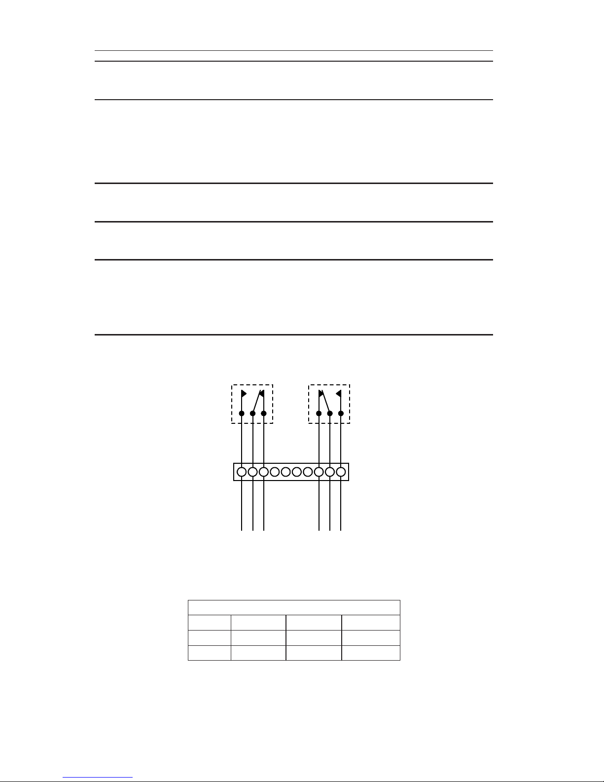
SwitchWiring
IMPORTANT: Figure 2.1 shows switch contacts in the relaxed (shelf) condition, the low
switch set to trip at a position below the pointer scale position, and the
high switch set to trip at a position above the pointer scale position. NO
= Normally Open in (shelf) condition. NC = Normally Closed in (shelf)
condition. C= Common.
LOW & HIGH SPDT SWITCHES
NO NOC CNC NC
RED
YELLOW
BLUE
RED
YELLOW
BLUE
WHITE
GREEN
BLACK
WHITE
GREEN
BLACK
1 2 3 4 5 6 7 8 9 10
Figure 2.1—Low/high SPDT switch diagrams
Table2.1—SwitchWireColorCoding
580ACurrentCongurations
NO C NC
Low Red Yellow Blue
High Black Green White
This manual suits for next models
1
Table of contents
Other Cameron Switch manuals


