Camozzi DRCS Series Operation instructions

Series DRCS
drive for Stepper motors
EN
USE AND MAINTENANCE INSTRUCTIONS

2
Contents
1. Product identification 3
2. General recommendations 3
3. General characteristics and conditions of use 4
4. Electrical circuit 4
5. Product transport and storage 4
6. System general description 5
7. Installation and start-up 5
7.1 DRCS power supply 6
7.2 DRCS encoder 6
7.3 Proximity connector 7
7.4 Motor connector 7
7.5 Brake connector 8
7.6 CANopen connector 8
7.7 25-pin SUB-D connector 8
7.8 Inputs 8
7.9 Outputs 9
7.10 Steps to realise a movement 10
7.11 PC requirements 10
8. Operation 11
9. Troubleshooting and/or exceptional circumstances 11
10. Limitations on use 11
11. Maintenance 11
12. Environmental notes 11

EN
Series DRCS drive for stepper motors
3
General recommendations
Product identification
1.
2.
The recommendations regarding safe use, described in this document, should be observed at all times.
• Some hazards can only be associated with the product after it has been installed on the machine/equipment.
It is the responsibility of the end user to identify these hazards and reduce the associated risks accordingly.
• The product described in this manual may be used in circuits that must comply with the standard EN ISO 13849-1.
• For information regarding component reliability, contact Camozzi.
• Before proceeding to use this product carefully read all information in this document.
• Keep this document in a safe place where it is accessible to all personnel throughout the product life cycle.
• This document should accompany the product in the event of transfer to a new owner or user.
• The instructions in this manual must be observed together with the instructions and additional information available from
the following references:
- website http://www.camozzi.com
- Camozzi general catalogue
- Technical assistance service
• Based on these instructions, only qualified and authorised personnel must perform assembly and start-up operations.
• It is the responsibility of the system/machine designer to ensure the correct selection of the most suitable pneumatic
component according to the intended application.
• It is recommended to use suitable protection to minimise the risk of physical injury.
• For all situations not covered in this manual and in situations in which there is a potential risk of damage or injury to
objects, persons or animals, contact Camozzi for advice.
• Never make unauthorised modifications to the product. In this case, any damage or injury to objects, persons or animals
will be the responsibility of the user.
• All relevant product safety standards must be observed at all times.
• Never interfere with the machine/system before verifying that all working conditions are safe.
• Before installation and maintenance, ensure that the envisaged safety locks are active. In particular, disconnect the
electrical mains (if necessary) and system pressure supply, thereby discharging all residual compressed air from the circuit
and deactivating residual energy stored in springs, condensers, recipients and gravity.
• After installation or maintenance, the system pressure and electrical power supply (if necessary) must be connected,
after which the operator must check correct operation and sealing efficiency of the product. In the event of sealing failure
or malfunction, the product must not be used.
• The product may only be used with adherence to the specifications provided; if these requirements are not met, the product
may only be used with authorization from Camozzi.
• Avoid covering the equipment with paint or other substances that may reduce heat dissipation.
Conversion table for the production date
The products are designed and manufactured in conformity with the following directives: 2014/30/UE
They also comply partially or totally regarding the applicable parts of the following standards: CEI EN 61131-2
Position 1 and 2:
n° of the week
01 14 27 40
02 15 28 41
03 16 29 42
04 17 30 43
05 18 31 44
06 19 32 45
07 20 33 46
08 21 34 47
09 22 35 48
10 23 36 49
11 24 37 50
12 25 38 51
13 26 39 52
Example of composition
03P
Description:
03 Week n° 03
PYear 2010
Position 3:
one letter for the present year
A1996 2021 2046
B1997 2022 2047
C1998 2023 2048
D1999 2024 2049
E2000 2025 2050
F2001 2026 2051
G2002 2027 2052
H2003 2028 2053
I2004 2029 2054
K2005 2030 2055
L2006 2031 2056
M2007 2032 2057
N2008 2033 2058
O2009 2034 2059
P2010 2035 2060
Q2011 2036 2061
R2012 2037 2062
S1988 2013 2038 2063
T1989 2014 2039 2064
U1990 2015 2040 2065
V1991 2016 2041 2066
W1992 2017 2042 2067
X1993 2018 2043 2068
Y1994 2019 2044 2069
Z1995 2020 2045 2070

EN
Series DRCS drive for stepper motors
4
Product transport and storage
5.
• Take all possible measures to avoid accidental damage to the product during transport, and use the original packaging
if available.
• Observe the specified storage temperature.
General characteristics and conditions of use
3.
Electrical circuit
4.
Assembly position Any
Overall dimensions L = 122,6 mm; W = 113,2 mm; H = 39 mm
Weight 460 g (approx.)
Ambient temperature 0 - 40°C (up to 55°C with forced ventilation)
Storage temperature -20°C ÷ 70°C
Ambient humidity Max 90%
IP protection rating according to EN 60529 IP20
Vibrations 1G (10 to 500 Hz)
Altitude < 1000 meters
Electrical logic supply 18 - 32 V DC
Electrical power supply 24 - 60 V DC
Current 0,1 - 5 A (limited by fuse)
Holding current Automatic reduction of the holding current with motor stopped,
set in the “holding current” function as a current or time value
Protection Overvoltage, undervoltage, over temperature, short circuit and earth fault
Method of control 4 PWM states 20kHz
Type of amplification Dual H-Bridge, 4 Quadrants
Control position Encoder 100 to 5000 differential pulses / revolution
Control signal Input 12 opto-isolated 24 V DC
Control signal Output 6 opto-isolated
Frequency Input Step and direction input, max frequency 60kHz, 5V
Brake control signal Output Electromechanical brake, max current 1 A
USB USB 2.0
Bluetooth BL 2.1 + EDR and BLE 4.0 standard (only for models DRCS-XXX-X-X-X-B)
RFID With NFC device
CANopen CANopen standard (CiA 402 and 301 profiles)
Microstep emulation High resolution via micro-stepping and accurate synchronisation
Reduction of oscillations and vibrations due to resonance
Anti-resonance Activation of the oscillation system in order to reduce the vibrations to obtain
smooth motion and speed control, by dampening the oscillation time
Signalling Green Led
Configuration Digital, using Camozzi’s configuration software QSet
Control methods Digital Inputs, Frequency, CANopen (only for models DRCS-XXX-X-C-X-X)
Data retention memory Flash
Data backup memory E²prom
Input 1
to
Input 12
18-24 V DC
18-60 V DC
Motor
Encoder
Input
encoder
Power supply
(power)
Optoisolated
Input-
Output
CANopen
Serial
communication
Power
amplifier
PWM Mosfet
Internal
power supply
DSP
To Plc
Brake
To PC USB
Output 1
to
Output 6

EN
Series DRCS drive for stepper motors
5
System general description
Installation and start-up
6.
7.
The Camozzi DRCS drive has been developed to optimise the performance of Camozzi Stepper motors.
By using the micro-stepping technology (resolution up to 1/16 of step) it is possible to obtain a near-perfect sinusoidal
current, thus significantly reducing the natural resonance of the motor.
Many different control methods are available:
• Digital control: the availability of 7 inputs allows the realisation of a command table of 128 lines and for each command
line it is possible to set the position, the speed, the acceleration and deceleration. Each command can be either absolute
or relative.
• Frequency control: it is possible to configure the drive frequency control using commands Step and Direction.
The step rate defines the speed and the number of steps defines the position.
• CANopen control (only for models DRCS-XXX-X-C-X-X): it is possible to control the DRCS drive via CANopen (profile
standards CiA301 and CiA402)
The DRCS drive can be configured via USB or wirelessly using the Bluetooth protocol (only for models DRCS-XXX-X-X-X-B).
The DRCS drive is configurable through Camozzi’s software QSet (for more details on using this configurator and its
features, refer to the specific manual).
• During unpacking, take great care not to damage the product.
• Check if there are any faults from transportation or storage of the product.
• Separate all packaging material to allow for the recovery or disposal in accordance with current regulations in the country of use.
• Before using the component, ensure that the stated specifications and performance features correspond to what is required.
• During installation, ensure that suitable surge protection devices are used.
• During installation, verify that no hazards due to mechanical movements are introduced.
• Install the component in an area where the set-up and maintenance operations are easily performed without creating a
hazard for the operator.
• Isolate any unused connection wires with suitable safety caps or covers.
• The components must be fixed properly, where possible, using appropriate fasteners and ensuring that the fixture remains
effective even when the actuator operates at a high frequency or in the presence of strong vibrations.
• In the event of strong vibrations, provide suitable devices or systems that can dampen the effect these vibrations have
on the drive.
• Provide for the installation of dehumidifiers in order to prevent moisture or condensation in the internal components.
• If the device is used to operate an actuator of which any accidental movement can create a hazard, provide suitable
locking devices on the mobile section of the actuator.
• Ensure that the connectors are connected and secured properly.
• The device can be fastened on a DIN rail with the appropriate accessory, PCF-E520, mounted on the rear of the body.
• The component can be fixed directly to a support using the 8 holes (2 of which have an M6 thread) present on the both
sides of the body.
Proximity
Encoder / Step
and direction
USB
CANopen
Brake
Logic 24V
Power 48V
Motor
I/O
NFC
Bluetooth
Inside

EN
Series DRCS drive for stepper motors
6
7.1 DRCS Power Supply
When choosing the power supply, adhere to all regulatory and safety requirements of the DRCS drive, presented in this
manual.
It is important to choose the correct voltage and current.
It is important to use power supplies equipped with “soft start” to avoid inrush currents that could damage the DRCS drive.
• Voltage
The supply voltage must be regulated and stabilised so as to avoid losses in speed and torque.
For Stepper motors, the voltage is directly proportional to motor speed.
• Current
The required current should be the sum of the two phase currents, but the DRCS drive controls the current with frequency
modulation, so it requires less current. In particular, the current required when operating at 24V will be double than that
required when operating at 48V.
In order to size the power supply correctly, we recommend using a power supply with double the expected current
capacity and analyse the operation at full load with a current probe. This will indicate the maximum current rating
required for successful operation.
• The information that follows shows the pinouts and details of the various connector ports located on the front of the
DRCS module:
Inside the DRCS drive, there is a non-resettable fuse that protects the logic circuit. If a replaceable fuse is necessary,
connect a 3A fast-blow fuse externally, in-line with the power cable. The logic power is applied to the LOGIC 24V
connector; use copper wires with an AWG22 cross section.
Warning: reversing the positive and negative poles can damage the DRCS drive.
Inside the DRCS drive, there is a non-resettable fuse that protects the logic circuit. If a replaceable fuse is necessary, connect
an 8A ultra fast (FF) blow fuse externally, in-line with the power cable.
The motor power is applied to the POWER 48V connector; use copper wires with an AWG18 cross section.
Warning: reversing the positive and negative poles can damage the DRCS drive.
7.2 DRCS Encoder
A differential connection for the encoder powered with +5V is available and a single-ended connection connects the signals
A+, B+ and Z+ to the +5V. The following picture shows the internal connection on DRCS drive.
LOGIC 24V 2-POLE FEMALE CONNECTOR (LOGIC)
Pin Signal Description
1L24V 24V DC power supply (logic): connect to the positive pole
of the 24V DC power supply (ref. GND)
2GND Common (reference pin 1): connect to the negative pole
of the 24V DC power supply (compulsory).
POWER 48V 4-POLE FEMALE CONNECTOR (POWER)
Pin Signal Description
1P48V 48V DC power supply (power): connect to the positive pole
of the 48V DC power supply (ref. GND)
2
3GND Common (ref. for pin 1 and 2): connect to the negative pole
of the 48V DC power supply (compulsory)
4
Pin Signal Mode Description
DIGITAL INPUT or CANopen
Mode Description
STEP-DIRECTION
1+5V +5V power supply for external encoder (ref. GND)
2FASE B- Encoder phase B negative pole Direction input negative pole
3FASE Z- Encoder phase Z negative pole Not used
4FASE B+ Encoder phase B positive pole Direction input positive pole
5FASE Z+ Encoder phase Z positive pole Not used
6FASE A- Encoder phase A negative pole Step input negative pole
7GND Common (ref. for pin 1)
8FASE A+ Encoder phase A positive pole Step input positive pole
9GND Common (ref. for pin 1)
10 SHIELD Encoder cable shield Not used
J12
109
2
4
6
87
5
3
1
+5Venc
E
Z-
B-
B+
A-
A+
Z+
ACPL-M61L
U25
6
5
4
3
1
R76
R68
1K 1% 1/8W
560 5% 1/8W
Z+
Z-
3V3
ACPL-M61L
U25
6
5
4
3
1
R76
R68
1K 1% 1/8W
560 5% 1/8W
A+
A-
3V3
ACPL-M61L
U25
6
5
4
3
1
R76
R68
1K 1% 1/8W
560 5% 1/8W
B+
B-
3V3
ACPL-M61L
U25
6
5
4
3
1
R76
R68
1K 1% 1/8W
560 5% 1/8W
Z+
Z-
3V3
ACPL-M61L
U25
6
5
4
3
1
R76
R68
1K 1% 1/8W
560 5% 1/8W
A+
A-
3V3
ACPL-M61L
U25
6
5
4
3
1
R76
R68
1K 1% 1/8W
560 5% 1/8W
B+
B-
3V3
ACPL-M61L
U25
6
5
4
3
1
R76
R68
1K 1% 1/8W
560 5% 1/8W
Z+
Z-
3V3
ACPL-M61L
U25
6
5
4
3
1
R76
R68
1K 1% 1/8W
560 5% 1/8W
A+
A-
3V3
ACPL-M61L
U25
6
5
4
3
1
R76
R68
1K 1% 1/8W
560 5% 1/8W
B+
B-
3V3

EN
Series DRCS drive for stepper motors
7
It is possible to connect two proximity switches, one for Homing functionality and another for various functions:
1. Extra stroke sensor
2. Stop movement command (use it for stop the movement before to reach the target position)
Is possible to use both NPN and PNP proximity switches.
Stepper motors can have 4- or 8- wire configurations; the following pictures show these configurations and the connections
for the most common types of Stepper motors. The motor must be connected to the MOTOR connector:
4-wire motor:
8-wire motor:
As shown in the following picture, the 8-wire motors permit two different connection schemes: series or parallel.
In the series connection scheme, the high-speed torque is lower, but the losses and operating temperature are also reduced.
With this scheme, it is recommended to decrease the phase current by at least 30%.
In the parallel connection scheme, the torque and speed of the motor follow the torque-speed characteristic curve.
7.3 Proximity connector
7.4 Motor connector
Pin Signal Description
1+24V +24V power for external proximity (ref. GND)
2HMG Input for Homing sensor
3GND Common (ref. for pin 1)
4EXCOM1 Excom1 common (PNP=GND and NPN=+24V DC)
5GND Common (ref. for pin 1)
6OPT Input for Proximity / external stop (optional)
Pin Signal Description
1B- Motor phase B negative pole
2B-
3A- Motor phase A negative pole
4A-
5B+ Motor phase B positive pole
6B+
7A+ Motor phase A positive pole
8A+
3
4
2
1
EXcom1
Q
R46
2K2 5% 1/2W
3
4
Q
2
1
3
FINE CORSA NPN
+24V
FINE CORSA PNP
2
1
3
2
1
R46
2K2 5% 1/2W
Excom1
3
4
2
1
EXcom1
Q
R46
2K2 5% 1/2W
3
4
Q
2
1
3
FINE CORSA NPN
+24V
FINE CORSA PNP
2
1
3
2
1
R46
2K2 5% 1/2W
Excom1

EN
Series DRCS drive for stepper motors
8
Pin Signal Description
1+24V +24V power supply (ref. GND_B)
2
3GND_B Common (ref. for pin 1)
4
Pin Signal Description
1GND Common (ref. for pins 5 and 6)
2
3CANL CAN-L bus
4CANH CAN-H bus
524V_C Positive power supply for the bus (24V DC) - Optional
6
6
5
4
3
2
1
The DRCS drive allows for the connection of a DC electromechanical brake; the control current must exceed 0.6A.
The brake is controlled automatically by synchronising with the enable signal:
- If the enable signal (ENB) is enabled, the brake is open (brake powered)
- If the enable signal (ENB) is disabled, the brake is closed (brake not powered)
7.8 Inputs
- Proximity (PIN 2): an extra stroke/stop input that, if set, causes the motor to stop using the ramp deceleration setted by
the actual movement.
- Homing input (PIN 3): defines the zero position; the method used to conduct the Homing procedure is configurable with
Camozzi’s QSet software (for more details on using the configurator, specifically this feature, refer to the manual).
In order to activate the Homing procedure, it is necessary to follow these steps:
- Deactivate all inputs, from IN0 to IN7
- Activate the Enable input
- Activate the Strobe input: the procedure starts with the rising edge.
Digital Inputs IN0-IN6
The digital inputs’ common pin (EXCOM) can be connected to either the negative or positive pole of the power supply.
Every program line set in QSet (for more details on using the configurator, specifically this feature, refer to the manual)
corresponds to the binary combination of digital inputs as shown on the following page:
Pin Signal Description
1EXCOM1 Proximity and Homing sensors common (ref. for pins 2 and 3)
2OPT Input for proximity/stop sensor (optional): refer to PROXIMITY connector
3HMG Input for Homing sensor: refer to PROXIMITY connector
4ENB Enable Input
5STB Strobe Input
6IN7 Input 7 / Jog- input
7IN6 Input 6 / Jog+ input
8IN5 Input 5
9IN4 Input 4
10 IN3 Input 3
11 IN2 Input 2
12 IN1 Input 1
13 IN0 Input 0
14 EXCOM Common (ref. for pins 4 to 13)
15 +24V +24V power supply (ref. GND)
16 GND Common (ref. for pin 15)
17
18 RDY Ready positive collector Output (QSet = OUTPUT6)
19 HOK Homing OK positive collector Output (QSet = OUTPUT5)
20 POS In Position positive collector Output (QSet = OUTPUT4)
21 OUT+ Configurable positive collector Output (QSet = OUTPUT3)
22 OUT- Configurable negative emitter Output (QSet = OUTPUT3)
23 ALM Alarm positive collector Output (QSet = OUTPUT1)
24 BSY Busy positive collector Output (QSet = OUTPUT2)
25 GND_O Output common (ref. for pins 18, 19, 20, 23 and 24)
7.5 Brake connector
7.6 CANopen connector
7.7 25-pin SUB-D connector

EN
Series DRCS drive for stepper motors
9
The maximum number of selectable individual lines is 127 (Line 0 is reserved for Homing.
It is possible to connect either PNP or NPN devices to the inputs.
If the PNP type is desired, connect the EXCOM signal (pin 14 on I/O connector) to the negative pole of the power supply
(GND); otherwise, if NPN type is desired, connect EXCOM (pin 14 on I/O connector) to the positive pole of the power
supply (+24V).
The following picture show examples of each type of connection:
IN7 and IN6
Via the QSet software is possible to set some external Jog commands to the driver; by using IN7 and IN6 inputs
(respectively pin 6 and pin 7 on IO connector) is possible to command with pulse. Using IN7 and IN6 inputs as Jog
command, the number of row in the table showed above will be reduced from 127 rows to 63 command rows.
7.9 Outputs
The DRCS drive provides 5 open collector outputs (NPN type) with a common pin (GND_O) when is necessary to connect
this pin to the negative poles of the power supply and a differential output. The maximum current for Alarm and Busy
output is 50ma with maximum voltage 80 V DC, for the others outputs the limits are 150mA and 300V.
If the load is inductive (eg. a relay), it is necessary to connect a flyback diode.
If the load is an input module (eg. a PLC), connect a reverse-polarity protection device, if not already provided by the input
module.
If the load could require a current greater than the maximum, connect a resistor in order to limit the current.
When an output is activated, its level is low, for exempla the Alarm output level is high without error, but the level became
low when an error is present: in this way is easy to identify an error on cabling or a cable break.
The following picture show some examples of connection:
- Inductive load - Input module
Strobe IN7 IN6 IN5 IN4 IN3 IN2 IN1 IN0 Line number
á0 0 0 0 0 0 0 0 Homing
á0 0 0 0 0 0 0 1 Line 1
á0 0 0 0 0 0 1 0 Line 2
á0 0 0 0 0 0 1 1 Line 3
á0 0 0 0 0 1 0 0 Line 4
á0 0 0 0 0 1 0 1 Line 5
á0 0 0 0 0 1 1 0 Line 6
á0 0 0 0 0 1 1 1 Line 7
Line n
Line n+1
á1 1 1 1 1 1 1 1 Line 127
U38
3
4
2
1
+24Vdc
C50
R44
2K2 5% 1/2W
3V3
R11
1K3 5% 1/2W
470pF 50V
EXCOM
U38
3
4
2
1
+24Vdc
C50
R44
2K2 5% 1/2W
3V3
R11
1K3 5% 1/2W
470pF 50V
EXCOM
NPN
PNP
+24Vdc
U20
6
42
1
25 CCOM
TLP187
3V3
R62
180 5% 1/5W
K
A
U38
3
4
2
1
+24Vdc
C50
R44
2K2 5% 1/2W
3V3
R11
1K3 5% 1/2W
470pF 50V
EXCOM
U38
3
4
2
1
+24Vdc
C50
R44
2K2 5% 1/2W
3V3
R11
1K3 5% 1/2W
470pF 50V
EXCOM
NPN
PNP
25
U20
6
4
2
1
TLP187
3V3
R62
180 5% 1/5W
CCOM
R3
10K 5% 1/10W
+5V
Ingresso PLC
0V Alimentazione

EN
Series DRCS drive for stepper motors
10
PROG. TYP
COMMAND FORCE [N]
max 54 POSITION [mm]
max 1500 VELOCITY [mm/s]
max 3333 ACC [mm/s2]
max 5000 DEC [mm/s2]
max 5000
1 pos. Absolute 0.000 100.000 500.000 100.000 100.000
CPU 2.0 GHz or higher
RAM 2 GB or higher
HD space 600 MB or higher
Communication port USB 2.0
Operative system Windows 7, Windows 8
Screen resolution 1280x720
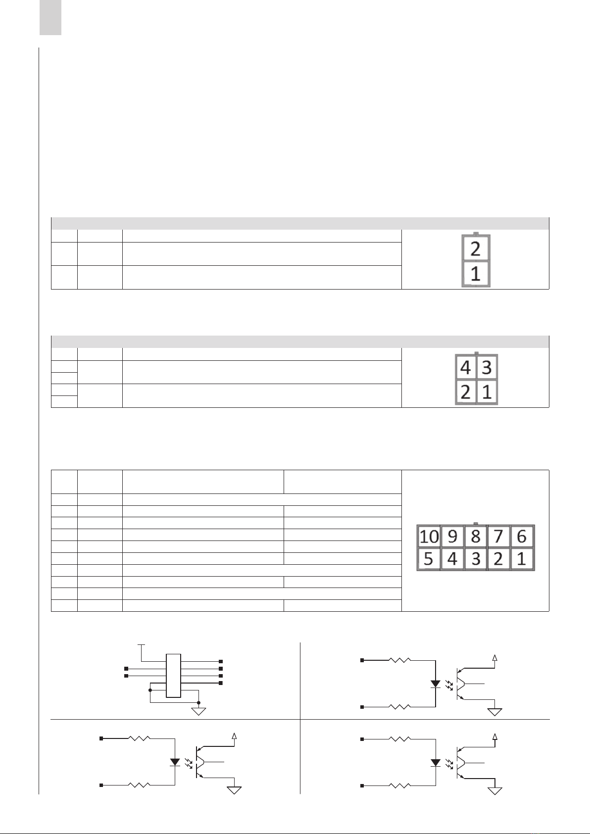
The available outputs are:
- Ready (RDY): indica che l’azionamento DRCS è abilitato senza allarmi, ed è pronto a ricevere un comando di moto.
- Homing OK (HOK): indica che la procedura di Homing (ricerca della posizione dio zero) è stata completata correttamente.
- Motore in posizione (POS): indica che il movimento è stato eseguito correttamente e la posizione è stata raggiunta.
- Busy (BSY): indica che il motore si sta muovendo e non può ricevere un ulteriore comando.
- Allarme (ALM): indica uno stato di allarme; nella tabella di allarme sono riportate tutte le possibili cause di guasto.
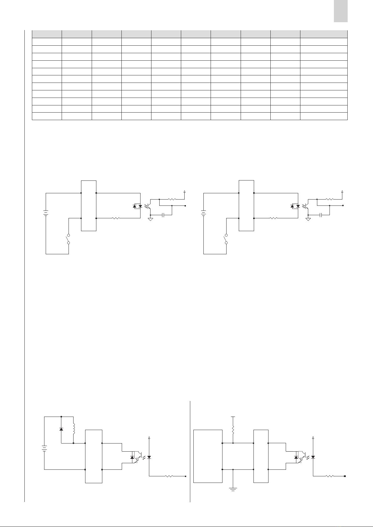
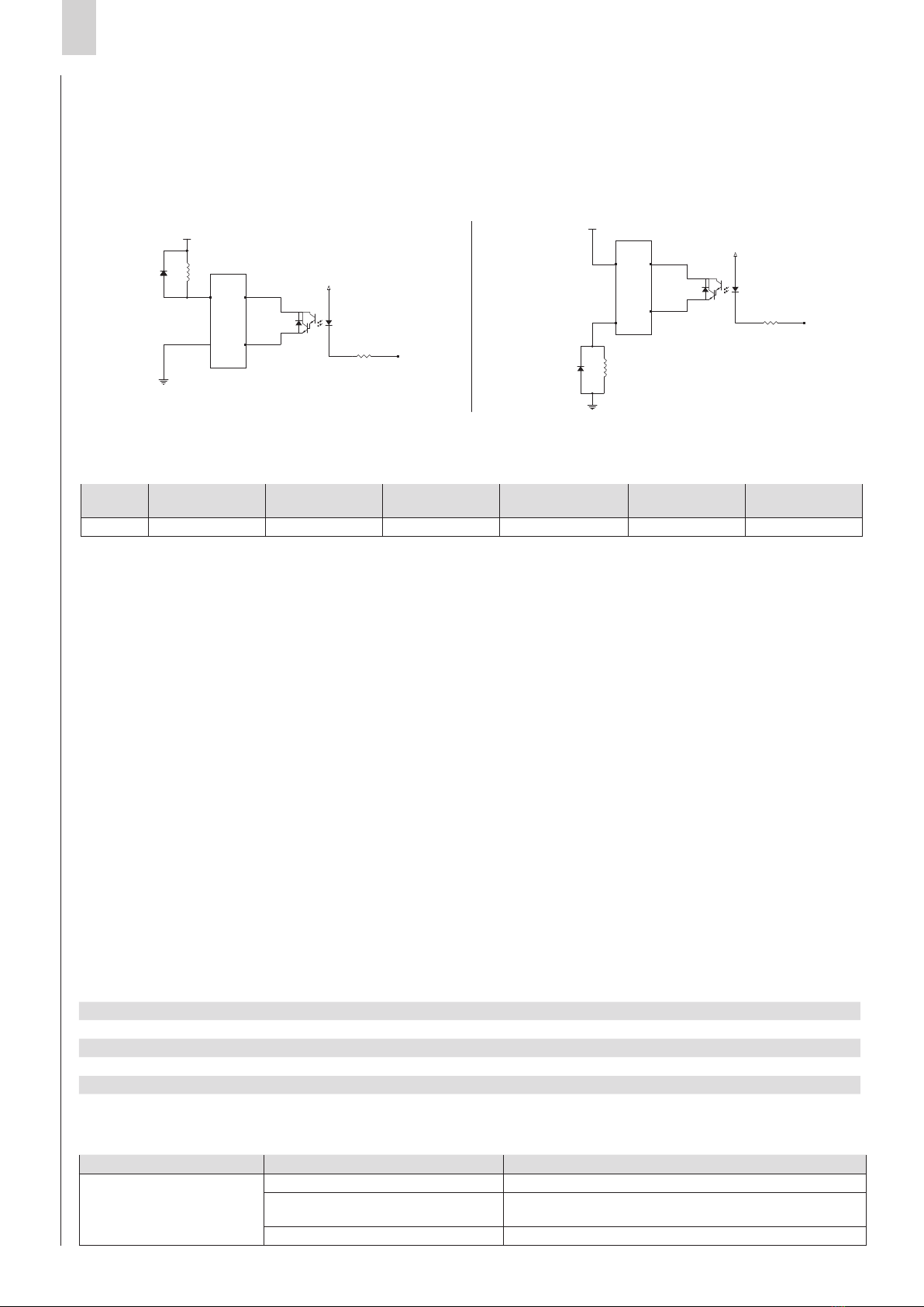
- Configurable output (OUT+ and OUT-): it is possible to set this output via the QSet software (for more details
on using the configurator, specifically this feature, refer to the manual) as either PNP or NPN type, as shown below.
7.10 Steps to realise a movement
• In QSet, configure one or more command lines and load them to the DRCS drive using the “PC to Drive” command.
Example: position 100 mm, velocity 500 mm/s, acceleration and deceleration 100 mm/s2 entered into row 1:
- Enable the DRCS drive by setting the Enable input (ENB).
- Deactivate all digital inputs (from IN0 to IN6) and verify, by observing the Ready output (RDY), that the DRCS drive is
ready. If yes, generate a pulse (minimum width of 2ms) on the Strobe input (STB); the Homing procedure then starts and
the Busy output (BSY) becomes active until the motion has ended.
- When the Homing procedure ends (refer to the Homing OK output (HOK), change the IN0 state to 1 and hold the inputs
IN1 ÷ IN6 at 0.
- Verify the Ready output (RDY) value and, if the DRCS drive is ready, generate a pulse (minimum width of 2ms) on the
strobe input (STB).
- When the movement starts, the In Position output (POS) is deactivated and the Busy output (BSY) is activated until the
motion ends.
- When the motion ends, the In Position output (POS) becomes active, the Busy output (BSY) is deactivated.
• The user must adopt the necessary measures to prevent damage to the system caused by voltage spikes on the power lines
as a result of power outages of high-energy equipment.
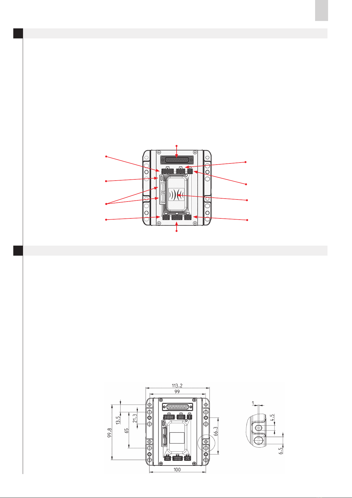
• The DRCS board does have protection against reverse polarity of the power supply voltage.
• To improve noise immunity and prevent damage, it is recommended to connect the device to the system ground using any
of the holes in the aluminium body, and attaching the conductor to the metal plate.
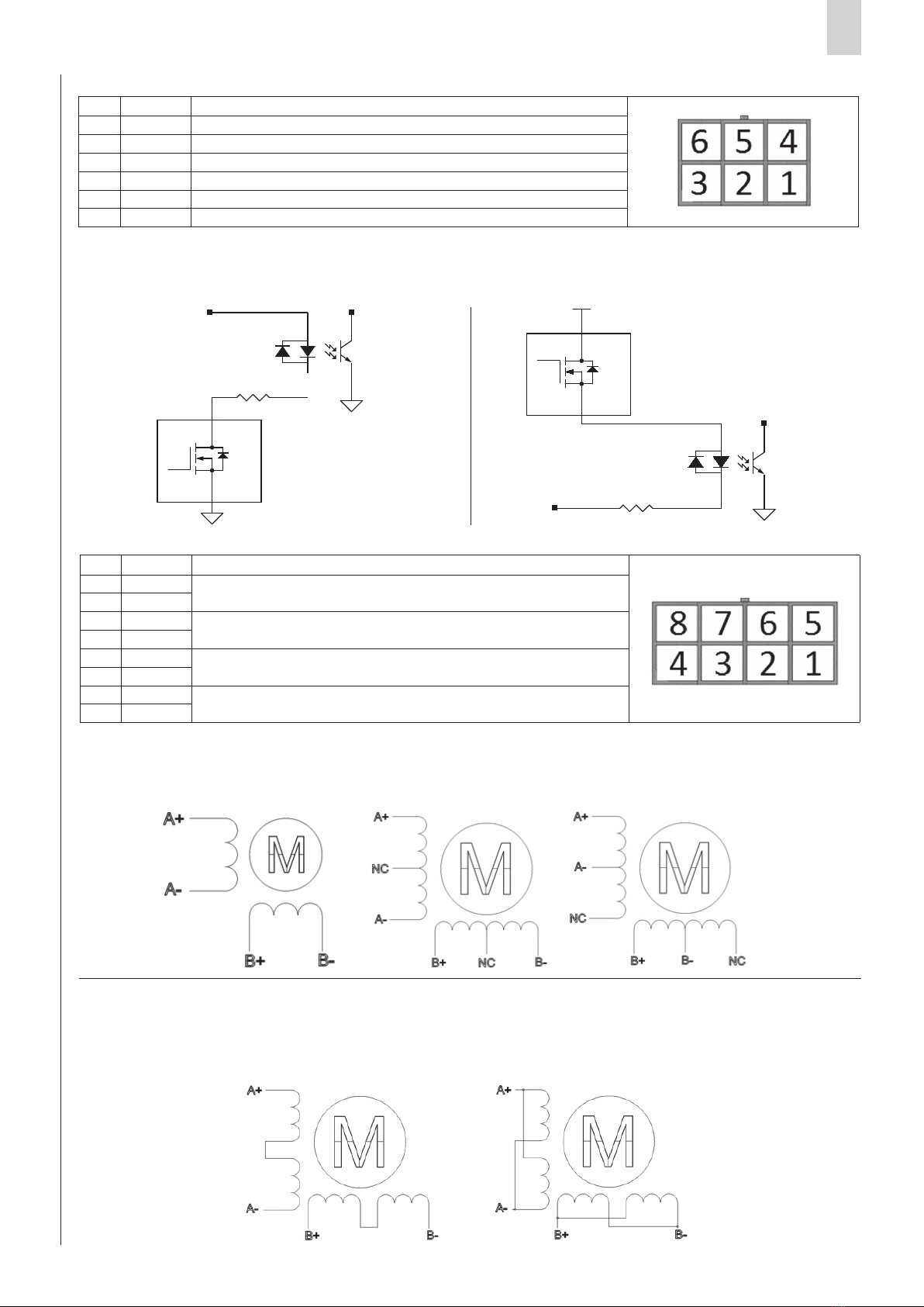
• Only for models DRCS-XXX-X-C-X-X, it is possible to set the node address, its baud rate (up to 1 M/s) and enable the
CANopen communication mode (disabled by default) via the QSet configuration software (for more details on using the
configurator, specifically this feature, refer to the manual).
If the DRCS drive is the last node of the CANopen segment, it is necessary to use the termination resistor for the bus: the
order code EC-060623 is for a DRCS drive that has this resistor installed, which can be mounted on one of the two
CANopen connectors.
• To configure the DRCS drive, download the QSet software setup file from http://www.camozzi.com and proceed with
installation following the on-screen instructions. For more details, please refer to the QSet manual.
The connection to the DRCS drive is standard Micro USB (available as an accessory: G11W-G12W-2); communication
is only possible if the USB driver is correctly installed on PC.
The USB driver is installed automatically during the QSet installation.
7.11 PC requirements
• On start-up of the QSet software, the system verifies communication between the DRCS drive and the PC where the
configuration software is installed. In the event of communication failure, an error message is displayed.
Type of fault Cause Solution
Communication failure
between DRCS drive and PC
Power supply not connected Connect the electrical power supply
USB cable not connected Connect the USB cable to one of the ports available
on the PC and to the Micro USB connector
USB driver not installed Contact the Camozzi technical assistance service
22
21
6
4
2
1
3V3
R62
180 5% 1/5W
+24V
NPN
A K
22
21
6
4
2
1
3V3
R62
180 5% 1/5W
+24V
PNP
22
21
6
4
2
1
3V3
R62
180 5% 1/5W
+24V NPN
A K
22
21
6
4
2
1
3V3
R62
180 5% 1/5W
+24V
PNP

EN
Series DRCS drive for stepper motors
11
Led Problem Solution
OFF The logic power supply is not present Check the power supply connector
LOGIC 24V
Solid The DRCS drive is powered and the connected
motor is disabled
Blink
0,5 HZ
The DRCS drive is powered and the connected
motor is enabled
Blink
1 HZ
The DRCS drive is powered, the connected motor
is enabled and the Homing procedure is completed
Fast
blink An alarm is present Identify the type of alarm according to the number
of times the LED flashes (described below)
Led Description Drive status
•solid Motor disabled
••flashing slow (0,5Hz) Motor enabled without homing
••flashing normal (1Hz) Motor ready to move (enabled + homing completed)
•••••••••• flashing 1 time Alarm: motor not configured
•••••••••• flashing 2 times Alarm: Homing
•••••••••• flashing 3 times Alarm: overflow limit
•••••••••• flashing 4 times Alarm: undervoltage
•••••••••• flashing 5 times Alarm: thermal
•••••••••• flashing 6 times Alarm: overcurrent
•••••••••• flashing 7 times Alarm: step lost (if encoder is present)
•••••••••• flashing fast (>1Hz) Alarm: on serial communication
Operation
Troubleshooting and/or exceptional circumstances
8.
9.
• Ensure that the electrical power supply and all other operating conditions remain within their specified range.
• The product may only be used in accordance with the specifications provided; if these requirements are not met, the
product may only be used with authorization from Camozzi.
• Observe the specifications on the nameplate.
• The following table explains the indication of the LED on the top panel of the DRCS drive:
• The following table describes the LED indication of alarms:
Limitations on use
Maintenance
Environmental notes
10.
11.
12.
• Never exceed the technical specifications stated in the paragraph “General characteristics” and the Camozzi general catalogue.
• With the exception of specific intended applications, do not use the product in environments where there is the risk of
direct contact with corrosive gases, chemical products, salt water, water or steam.
• Do not install the DRCS drive in spaces where air recirculation is not limited, as the fan will not be able to maintain an
environment below 40°C.
• Do not install the DRCS drive in areas with high levels of humidity.
• If maintenance is performed incorrectly, it can affect proper operation of the device and it could cause harm or damage to
persons or objects in its vicinity.
• Check that all components are secure and disconnect the power supply to release residual charge from the system before
performing work.
• Check whether it is possible to have the product serviced at a technical assistance centre.
• Never disassemble a live unit.
• Shut off electric supplies before maintenance.
• Always remove accessories before maintenance.
• Always wear the correct personal protective equipment as required by local authorities and in compliance with current
legislation.
• If replacement of worn parts is required, use only the original Camozzi kit and ensure that the work is performed by
specialised and authorised personnel. Otherwise, product certification will be rendered invalid.
• At the end of the product’s life cycle, separate the components into their respective material types for recycling.
• Comply with all current standards and local regulations regarding waste disposal.
• The product and its components are in compliance with the standards ROHS and REACH.

www.camozzi.com
A Camozzi Group Company
5000002102 rev.A
Contacts
Camozzi Automation spa
Società Unipersonale
Via Eritrea, 20/I
25126 Brescia - Italy
Tel. +39 030 37921
Fax +39 030 2400430
www.camozzi.com
Technical assistance
Product inquiries and
requests for support
Tel.+39 030 3792790
Product Certification
Information concerning
product certifications, EC standards,
conformity declarations and instructions
productcertifi[email protected]
Camozzi Worldwide
Details about our sales network can be found
on the Camozzi website in the Contacts section
Continuous Innovation
Other manuals for DRCS Series
1
Table of contents
Other Camozzi DC Drive manuals
Popular DC Drive manuals by other brands

Sumitomo
Sumitomo Invertek Drives Elevator Core Installation & operating instructions

Delta Tau
Delta Tau Geo MACRO User manual and reference guide

SOMFY
SOMFY mMotion Plus manual

FMX
FMX TD 400 Series quick start guide

elero
elero RolMotion M-868 Operating and assembly instructions

Altec Lansing
Altec Lansing HF DRIVER - REPAIR Repair

Toshiba
Toshiba S15 Startup guide

TIME LED
TIME LED 781289 Installation and operating instructions

Lenze
Lenze L-force 8400 Series Mounting instructions

Speck pumpen
Speck pumpen BADU Eco Drive II manual

Lincoln Electric
Lincoln Electric MAXsa 29 Operator's manual

Crane Source
Crane Source Spacevector SV200 manual