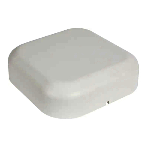
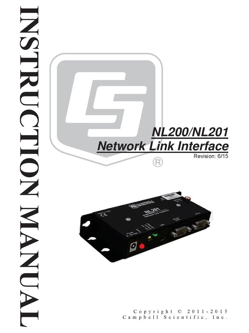
Campbell NL200 User manual

NL200/NL201
Network Link Interface
Issued: 23.10.13
Copyright © 2011-2013 Campbell Scientific Inc.
Printed under licence by Campbell Scientific Ltd.
CSL 942
USER MANUAL


Guarantee
This equipment is guaranteed against defects in materials and workmanship.
This guarantee applies for twelve months from date of delivery. We will
repair or replace products which prove to be defective during the guarantee
period provided they are returned to us prepaid. The guarantee will not apply
to:
•Equipment which has been modified or altered in any way without the
written permission of Campbell Scientific
•Batteries
•Any product which has been subjected to misuse, neglect, acts of God or
damage in transit.
Campbell Scientific will return guaranteed equipment by surface carrier
prepaid. Campbell Scientific will not reimburse the claimant for costs incurred
in removing and/or reinstalling equipment. This guarantee and the Company’s
obligation thereunder is in lieu of all other guarantees, expressed or implied,
including those of suitability and fitness for a particular purpose. Campbell
Scientific is not liable for consequential damage.
Please inform us before returning equipment and obtain a Repair Reference
Number whether the repair is under guarantee or not. Please state the faults as
clearly as possible, and if the product is out of the guarantee period it should
be accompanied by a purchase order. Quotations for repairs can be given on
request. It is the policy of Campbell Scientific to protect the health of its
employees and provide a safe working environment, in support of this policy a
“Declaration of Hazardous Material and Decontamination” form will be
issued for completion.
When returning equipment, the Repair Reference Number must be clearly
marked on the outside of the package. Complete the “Declaration of
Hazardous Material and Decontamination” form and ensure a completed copy
is returned with your goods. Please note your Repair may not be processed if
you do not include a copy of this form and Campbell Scientific Ltd reserves
the right to return goods at the customers’ expense.
Note that goods sent air freight are subject to Customs clearance fees which
Campbell Scientific will charge to customers. In many cases, these charges are
greater than the cost of the repair.
Campbell Scientific Ltd,
Campbell Park, 80 Hathern Road,
Shepshed, Loughborough, LE12 9GX, UK
Tel: +44 (0) 1509 601141
Fax: +44 (0) 1509 601091
www.campbellsci.co.uk


PLEASE READ FIRST
About this manual
Please note that this manual was originally produced by Campbell Scientific Inc. primarily for the
North American market. Some spellings, weights and measures may reflect this origin.
Some useful conversion factors:
Area: 1 in2(square inch) = 645 mm2
Length: 1 in. (inch) = 25.4 mm
1 ft (foot) = 304.8 mm
1 yard = 0.914 m
1 mile = 1.609 km
Mass: 1 oz. (ounce) = 28.35 g
1 lb (pound weight) = 0.454 kg
Pressure: 1 psi (lb/in2) = 68.95 mb
Volume: 1 UK pint = 568.3 ml
1 UK gallon = 4.546 litres
1 US gallon = 3.785 litres
In addition, while most of the information in the manual is correct for all countries, certain information
is specific to the North American market and so may not be applicable to European users.
Differences include the U.S standard external power supply details where some information (for
example the AC transformer input voltage) will not be applicable for British/European use. Please
note, however, that when a power supply adapter is ordered it will be suitable for use in your country.
Reference to some radio transmitters, digital cell phones and aerials may also not be applicable
according to your locality.
Some brackets, shields and enclosure options, including wiring, are not sold as standard items in the
European market; in some cases alternatives are offered. Details of the alternatives will be covered in
separate manuals.
Part numbers prefixed with a “#” symbol are special order parts for use with non-EU variants or for
special installations. Please quote the full part number with the # when ordering.
Recycling information
At the end of this product’s life it should not be put in commercial or domestic refuse
but sent for recycling. Any batteries contained within the product or used during the
products life should be removed from the product and also be sent to an appropriate
recycling facility.
Campbell Scientific Ltd can advise on the recycling of the equipment and in some cases
arrange collection and the correct disposal of it, although charges may apply for some
items or territories.
For further advice or support, please contact Campbell Scientific Ltd, or your local agent.
Campbell Scientific Ltd, Campbell Park, 80 Hathern Road, Shepshed, Loughborough, LE12 9GX, UK
Tel: +44 (0) 1509 601141 Fax: +44 (0) 1509 601091
www.campbellsci.co.uk


Contents
PDF viewers: These page numbers refer to the printed version of this document. Use the
PDF reader bookmarks tab for links to specific sections.
1. Introduction................................................................1
2. Cautionary Statements..............................................1
3. Quickstart...................................................................1
3.1 Physical Setup......................................................................................1
3.2 Configuring the NL200/201.................................................................2
3.3 LoggerNet Setup ..................................................................................3
3.4 Connect ................................................................................................4
4. Overview.....................................................................4
5. Specifications ............................................................8
6. Configuring the NL200/201........................................9
6.1 Configuring the NL200/201 via USB ..................................................9
6.2 Configuring the NL200/201 via Network Connection.......................10
6.3 Configuring the NL200/201 via Telnet..............................................10
6.4 Configuring the NL200/201 via RS-232............................................11
7. Operation..................................................................11
7.1 PakBus Router....................................................................................11
7.1.1 Physical Setup.............................................................................12
7.1.2 Configuring the NL200/201........................................................12
7.1.3 LoggerNet Setup .........................................................................13
7.1.4 Connect .......................................................................................14
7.2 Bridge Mode ......................................................................................14
7.2.1 Physical Setup.............................................................................14
7.2.2 Configuring the NL200/201........................................................14
7.2.3 Configuring the Datalogger.........................................................14
7.2.4 LoggerNet Setup .........................................................................15
7.2.5 Connect .......................................................................................16
7.3 Serial Server.......................................................................................16
7.3.1 Physical Setup.............................................................................16
7.3.2 Configuring the NL200/201........................................................16
7.3.3 LoggerNet Setup .........................................................................17
7.3.4 Connect .......................................................................................18
7.3.5 Serial Sensors..............................................................................18
7.4 TLS ....................................................................................................18
7.4.1 TLS Proxy Server........................................................................19
7.4.2 DevConfig TCP Encrypted Communication to the
NL200/201...............................................................................21

ii
8. Applications.............................................................22
8.1 Working Around Firewalls ................................................................22
8.1.1 Configuring the NL200/201........................................................22
8.1.2 Configuring the Datalogger ........................................................23
9. Troubleshooting ......................................................23
Appendices
A. Glossary................................................................. A-1
B. Cables, Pinouts, LED Function, and Jumper....... B-1
B.1 CS I/O ..............................................................................................B-1
B.2 RS-232 .............................................................................................B-1
B.3 Ethernet............................................................................................B-1
B.4 USB..................................................................................................B-2
B.5 Power ...............................................................................................B-2
B.6 LEDs ................................................................................................B-3
B.7 Power Jumper (NL201 only)............................................................B-3
C. NL200/201 Settings................................................ C-1
C.1 Main Tab..........................................................................................C-1
C.2 RS-232 Tab......................................................................................C-4
C.3 CS I/O Tab.......................................................................................C-6
C.4 Net Services Tab..............................................................................C-7
C.5 TLS Proxy Server Tab .....................................................................C-9
C.6 TLS Tab .........................................................................................C-11
D. NL200/201 Driver Installation Instructions........... D-1
D.1 Installing on Windows XP ...............................................................D-1
D.2 Installing on Windows Vista............................................................D-3
D.3 Installing on Windows 7 ..................................................................D-4
D.4 Oops! What if you plug the NL200/NL201 into your computer
before installing the drivers? ........................................................D-4
E. Sending a New OS to the NL200/201.................... E-1
Figures
3-1. NL200 with CR800 (external power)...................................................2
3-2. NL201 with CR800 (powered by datalogger)......................................2
3-3. LoggerNet setup...................................................................................4
4-1. NL201..................................................................................................5
4-2. Bridge Mode enabled...........................................................................5
4-3. Bridge Mode disabled..........................................................................6
5-1. NL200/201 dimensions in inches.........................................................8
7-3. PakBus router LoggerNet setup .........................................................14
7-1. Bridge mode LoggerNet setup ...........................................................16
7-2. Serial server LoggerNet setup............................................................18
7-4. TLS proxy server configurations........................................................20
8-1. Working around firewalls ..................................................................22
iii
Tables
B-1. CS I/O Pinout...................................................................................B-1
B-2. RS-232 Pinout..................................................................................B-1
B-3. Ethernet Pinout.................................................................................B-2
B-4. USB Micro-B...................................................................................B-2
B-5. Power In...........................................................................................B-2
B-6. Power LED.......................................................................................B-3
B-7. Ethernet LED ...................................................................................B-3

iv

1
NL200/201 Network Link Interface
1. Introduction
The NL200/201 Network Link Interface allows Campbell Scientific dataloggers
and peripherals to communicate over a local area network or a dedicated Internet
connection. This serial to Ethernet interface can be connected to a datalogger’s
CS I/O port or other devices via RS-232.
2. Cautionary Statements
The first time an NL200/201 is attached to a datalogger and Bridge Mode is
enabled, the datalogger’s memory has to be reorganized to allow room in
memory for the IP stack. To avoid the loss of data, collect your data before
enabling Bridge Mode.
The device driver for the NL200/201 must be installed on your computer
before you can connect to the NL200/201 via USB. See Appendix D,
NL200/201 Driver Installation Instructions, for instructions on installing the
device driver.
Device Configuration Utility 2.05 or higher is required to communicate with
the NL200/201. The latest Device Configuration Utility can be downloaded
from our website at www.campbellsci.com/downloads.
CR1000, CR3000, and CR800-series dataloggers require operating system
version 23 or higher in order to operate with the NL200/201 in bridge mode.
The latest operating systems can be downloaded from our website at
www.campbellsci.com/downloads.
The NL200 is not powered over CS I/O or USB. An external power adapter
or power cable is required. The NL201 can be powered by the CS I/O port or
an external power adapter or power cable. If you wish to prevent the NL201
from being powered by the CS I/O port, see Appendix B, Cables, Pinouts,
LED Function, and Jumper.
Ensure maximum protection against surges. Use a shielded Ethernet cable
and external surge protection. Keep RS-232 and CS I/O connections short.
3. Quickstart
Out of the box, the NL200/201 is configured for operation as a PakBus Router. In
this mode, the NL200/201 can be used to communicate with Campbell Scientific
PakBus devices over an Ethernet / Internet network connection.
3.1 Physical Setup
Using the supplied serial cable, connect the NL201’s CS I/O port to the
datalogger’s CS I/O port. Alternatively, power the NL200 or NL201 through the
barrel-connector jack located on the edge of the device. Connect the NL200/201
to your network using an Ethernet cable, attaching one end of the cable to the
NL200/201’s Ethernet port and the other end to your network. Ensure that the
device is powered up by inspecting the Power LED.

NL200/201 Network Link Interface
2
Figure 3-1. NL200 with CR800 (external power)
Figure 3-2. NL201 with CR800 (powered by datalogger)
3.2 Configuring the NL200/201
INSTALL THE DEVICE DRIVER BEFORE plugging the
NL200/201 into your PC for the first time. You will need the
device driver properly installed before you can connect to the
NL200/201 via USB. See Appendix D, NL200/201 Driver
Installation Instructions, for instructions on installing the device
driver.
NOTE

User Manual
3
Ensure the NL200/201 is powered.
Connect the supplied USB cable between a USB port on your computer and
the USB port on the NL200/201.
Open Device Configuration Utility (DevConfig).
Under Device Type, select “NL200”.
Click the Browse button next to “Communication Port”.
Select the port labelled “NL200”.
Click OK.
Click Connect.
To enter a static IP address, select “disable”in the Use DHCP field. Then
input the IP Address, Network Mask, and Default Gateway. These values can
be provided by your network administrator.
If a dynamic address is to be used, the network information acquired via
DHCP can be seen on the NL200 tab.
Click Apply to save your changes.
It is recommended that a static IP address be given to the
NL200/201 for most applications so that the path to the device is
always known. If using a dynamic IP address acquired via DHCP
you may wish to configure the NL200/201 as a PakBus/TCP client.
3.3 LoggerNet Setup
The next step is to run LoggerNet and configure it to connect to the datalogger via
the NL200/201.
In LoggerNet’s Setup Screen, press Add Root and choose “IPPort”. Input the
NL200/201’s IP address and port number. The IP address and port numbers
are input on the same line separated by a colon. IPv6 addresses will need to
be enclosed in square brackets when specifying a port number. An IPv4
address may look like 192.168.1.100:6785. An IPv6 address may look like
[2001:db8::1234:5678]:6785. A fully qualified host name entry may look
like yourlogger.com:6785.
Add a PakBus Port (PakBusPort).
Add a PakBus Router (pbRouter). Input the PakBus address of the
NL200/201. The NL200/201’s default PakBus address is 678.
Add the datalogger and input the PakBus address of the datalogger.
Press Apply to save the changes.
You can verify that your settings are correct by selecting the datalogger in the
Network Map, selecting the Clock tab, and pressing Check Clocks. If your
settings are correct, you should see the current clock of your server and
datalogger.
NOTE

NL200/201 Network Link Interface
4
Figure 3-3. LoggerNet setup
3.4 Connect
You are now ready to connect to your datalogger using the LoggerNet Connect
Screen.
4. Overview
The NL200/201 Network Link Interface is a device used to communicate with
Campbell Scientific dataloggers and peripherals using an Ethernet 10/100 Mbps
communications link. The NL200/201 includes a CS I/O port and an RS-232 port
for communication. A USB device port is used for configuring the NL200/201
device.

User Manual
5
Figure 4-1. NL201
Bridge Mode Enabled
The NL200/201 can be configured to bridge Ethernet and CS I/O communications
(Bridge Mode enabled). This mode is used for providing access to the internal IP
functionality of the CR800/850, CR1000, and CR3000 (e.g., web page access,
email, FTP, etc.). Bridge mode does not utilize PPP. Instead, raw IP packets are
transferred between the Ethernet and CS I/O connections.
Figure 4-2. Bridge Mode enabled
Bridge Mode Disabled
With Bridge Mode disabled, the NL200/201 can be configured to act as a serial
server and/or a PakBus router. The NL200/201 can act as a serial server and
PakBus router simultaneously. However, each physical port (RS-232 and CS I/O)
is only associated with one service (Pakbus router, serial server, Modbus/TCP
Gateway, etc.) at a time. Therefore, you can have an RS-232 serial server and a
CS I/O serial server, an RS-232 serial server and a CS I/O PakBus router, an RS-
232 PakBus router and a CS I/O serial server, or an RS-232 PakBus router and a
CS I/O PakBus router. In addition, the NL200/201 can act as TLS proxy server.
The TLS proxy server is independent of other modes.

NL200/201 Network Link Interface
6
Figure 4-3. Bridge Mode disabled
Some reasons you might want to use each of these modes are described below.
Refer to Section 6, Configuring the NL200/201, and Section 7, Operation, for
information on setting up your NL200/201 for each mode.
Campbell Scientific’s LoggerNet software is used to communicate with the
dataloggers once the NL200/201 is configured properly and connected to a
network.
Bridge Mode
Allows access to datalogger’s internal IP functionality when a peripheral port
is not accessible. For example accessing the HTTP/webpage, email, and FTP
capabilities of a CR800/850, ET107, RAWS, or CS110.

User Manual
7
Serial Server
Allows access to a CR10X over Ethernet (RS-232 serial server) when used in
conjunction with an RS-232 to CS I/O (ME) adapter like the SC32B or
SC105.
Allows access to a serial sensor over Ethernet (RS-232 serial server).
Provides an Ethernet to RF500M Base. (RS-232 serial server).
PakBus Router
Allows access to a CR10X-PB over Ethernet.
Allows access to a CR200X over Ethernet.
Allows you to connect to a PakBus Device on the RS-232 port and a PakBus
Device on the CS I/O port using only one TCP port.
Allows a PakBus device on the RS-232 port and a PakBus device on the CS
I/O port to communicate with each other without routing through the
Ethernet.
Allows multiple computers to concurrently talk to PakBus devices connected
to the RS-232 and CS I/O ports.
TLS Proxy Server
Adds an encrypted Ethernet network interface to a datalogger that supports
CS I/O IP (bridge mode) communications.

NL200/201 Network Link Interface
8
5. Specifications
General
177 g (6.3 oz)
16 x 6.73 x 2.54 cm (6.3 x 2.65 x 1 in)
Figure 5-1. NL200/201 dimensions in inches
Power Input
NL201: CS I/O or barrel connector jack; not powered over USB
NL200: Barrel connector jack; not powered over CS I/O or USB
Power Requirements
7-20 VDC
50 mA active, 2 mA standby @ 13 VDC
Standby power is when the IPNetPower instruction has been used to
turn off power to the Ethernet. See the CRBasic help for an
example of using the IPNetPower instruction. Note that the
IPNetPower instruction is only applicable when the NL200/201 is
configured with Bridge Mode Enabled.
Operating Temperature
Standard: –25° to +50C
Extended: –55 to +85C
Configuration
Device Configuration Utility over USB or Ethernet
Telnet console over Ethernet
Terminal menu over RS-232
CS I/O Port
SDC 7, 8, 10, 11 (does not support ME)
9600 bps to 460.8 kbps
RS-232 Port
DTE
1200 bps to 115.2 kbps
NOTE

User Manual
9
Ethernet
10Base-T (full and half duplex), 100Base-TX (full and half duplex), Auto-
MDIX
Auto-IP (APIPA), IPv4, IPv6, ICMP/Ping, ICMPv6/Ping, TCP, DHCP
Client, SLAAC, DNS Client, HTTPS Proxy, Telnet Server, TLS, PakBus,
Modbus TCP/IP
Miscellaneous
Supports 20 simultaneous TCP connections
Up to 10 of the 20 TCP connections can be used for TLS
PakBus router supports 50 routes
Supports up to 15 concurrent Modbus server transactions
Compliance
RoHS Compliant
The NL200/NL201 is encased in metal and meets requirements for a Class B
device under European standards:
APPLICATION OF COUNCIL DIRECTIVE(S)
2004/108/EC
STANDARD(S) TO WHICH CONFORMITY IS DECLARED:
EN61326-1;2013
6. Configuring the NL200/201
The NL200/201 is configured using the Device Configuration Utility
(DevConfig). You can connect your NL200/201 to DevConfig using either a
network connection or USB.
6.1 Configuring the NL200/201 via USB
INSTALL the DEVICE DRIVER BEFORE plugging the
NL200/201 into your PC for the first time. You will need the
device driver properly installed before you can connect to the
NL200/201 via USB. See Appendix D, NL200/201 Driver
Installation Instructions, for instructions on installing the device
driver.
Ensure the NL200/201 is powered.
Connect the supplied USB cable between a USB port on your computer and
the USB port on the NL200/201.
Open DevConfig.
Under Device Type, select “NL200”.
Click the Browse button next to “Communication Port”.
Select the port labelled “NL200”.
Click OK.
Click Connect.
NOTE

NL200/201 Network Link Interface
10
Configure the NL200/201 as needed for your application.
Click Apply to save your changes.
6.2 Configuring the NL200/201 via Network Connection
The NL200/201 must have an IP address before connecting via a
network connection. If the address cannot be obtained via DHCP,
you will need to configure your NL200/201 via USB the first time it
is set up.
When the NL200/201 is in bridge mode, it cannot be configured via
a network connection. It can only be configured via USB or RS-
232.
Ensure the NL200/201 is powered and connected to your network.
Launch DevConfig.
Under Device Type, select “NL200”.
Check the box labelled “Use IP Connection”.
Click the Browse button next to “Communication Port”.
Select the NL200/NL201 to be configured from the resulting pop-up window.
Enter “nl200” in the TCP Password box. (“nl200” is the default
administrative password. It can be changed via the DevConfig
Deployment/NL200 tab.)
Click OK.
Click Connect.
Configure the NL200/201 as needed for your application.
Click Apply to save your changes.
6.3 Configuring the NL200/201 via Telnet
The NL200/201 must have an IP address before connecting via
Telnet. Configuration via Telnet is not available in bridge mode.
Ensure the NL200/201 is powered and connected to your network.
Create a Telnet session with the device over port 23.
Input the NL200/201 Admin Password (default password is nl200).
Type help to see a list of the functionality available when connected to the
NL200/201 through Telnet.
Type edit and press Enter to edit the settings of the NL200/201.
NOTES
NOTE
Other manuals for NL200
1
This manual suits for next models
1
Table of contents
Other Campbell Network Hardware manuals

Campbell
Campbell NL115 User manual

Campbell
Campbell NL200 User manual

Campbell
Campbell NL120 User manual

Campbell
Campbell RTMS SYSTEMS User manual

Campbell
Campbell NL120 User manual

Campbell
Campbell 38485 User manual

Campbell
Campbell NL115 User manual

Campbell
Campbell NL121 User manual

Campbell
Campbell SC932A User manual

Campbell
Campbell 4WPB100 User manual