CAMSO ATV R4S Guide

CAMSO ATV R4S
FOR ALL-TERRAIN VEHICLES
$'-8670(176 20
ATV R4S: 1099-01-1340

INTRODUCTION
These guidelines are designed to provide you with the information necessary to perform the
required adjustments to the System. The right adjustments have a direct impact on
performance and lifespan of the System’s components. It is important to follow closely the
instructions contained in this document in order to make the correct system adjustments and
thereby reach optimum system performance.
Follow all the instructions contained in this document. To make sure that every step has been
performed, a checklist is provided at the end of the instructions to verify that all the
adjustments have been made.
IMPORTANT
The warranty does not apply if the Track System was installed by someone other than a
Camso dealer or authorized distributor.
IMPORTANT
Verifying your adjustments on the systems is mandatory after the first use of the vehicle; the
track tension, alignment and angle of attack of each track system must be re-verified. Incorrect
adjustments can decrease the performance of the systems and result in premature wear or
breakage of certain components.
® and MC are trademarks of Camso inc.
All rights reserved. ©2019 Camso inc.
Printed in Canada.
1099-00-7731 - VERSION A

ADJUSTMENTS
IMPORTANT
Before starting the installation, verify that serial numbers are identical on all 4 track systems.
The serial number’s last digit (0, 1, 2, 3) indicates the mounting position on the vehicle. Lay
out the track systems accordingly. Refer to Figure 1 and Figure 2.
NOTE: If Track System serial numbers do not match, contact your authorized Camso dealer / distributor.
Figure 1
Figure 2

1
ADJUSTMENTS
NOTE: To make the following adjustments, position the
vehicle on a flat and level surface.
ANGLE OF ATTACK - FRONT SYSTEMS
To obtain the correct angle of attack on front Track
Systems, perform the following:
• Use handlebars to point tracks straight ahead.
• Temporarily apply pressure to the front of the track
to make stay flat on the ground.
• Stabilizing arm (
1
) must be attached to front anchor
bracket (
2
) mounted on vehicle. Figure 3.
Figure 3
• A Bubble Level (1) is attached to the inside of the
front frames. A perfectly centered bubble is
needed to adjust the angle of attack correctly. See
Figure 4.
.
Figure 4
NOTE: Before each measurement, temporarily apply
light pressure to the front of the track to make
sure that it stays flat on the ground.
• Loosen jam nut (1). Adjust length of rod end (2)
by rotating the steering limiter support plate on
(3) the stabilizing arm. Use a 30 mm wrench to
rotate support plate to obtain a perfectly
centered bubble in the level. Refer to Figure 5.
NOTE: Stabilizing arms on front Track Systems
incorporate a steering limiter support plate (3)
that is bent. This plate should be positioned
inwards, towards the vehicle.
Figure 5
• When angle of attack is correctly set, tighten
the jam nut (1) back against the stabilizing arm
to 40 N•m [30lb•ft] of torque. See Figure 6.
CAUTION: Follow the recommended torque when
tightening the jam nut. Over-tightening the nut
might damage the rod end.
Figure 6
• Once the centered bubble in the level indicates
that the angle of attack is correct, double-check
the setting by validating the distance from the
top of the back tires to the ground. Figure 7.

2
ADJUSTMENTS
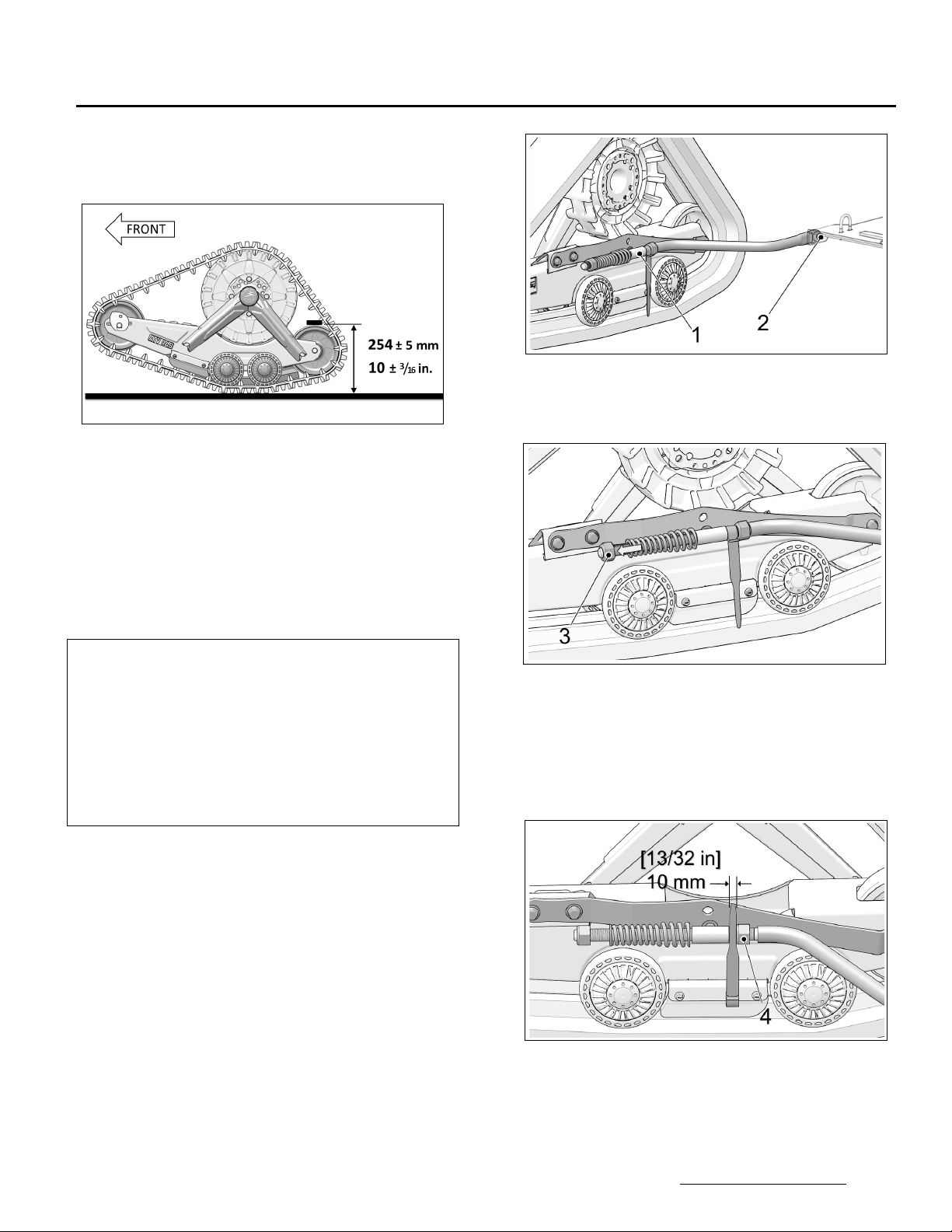
• Position a flat bar on top of the rear wheels of
the front Track System and measure from the
ground up to the flat bar as shown on Figure 7.
Figure 7
CAUTION: The 254 mm dimension corresponds to
the required angle of attack setting. If the centered
bubble in the level does not produce the required
measurement of 254 mm, re-adjust angle of attack
to obtain the required dimension without referring
to the bubble level.
NOTE: Once angle of attack adjustment on front
systems is completed, verify once more to
confirm adjustment setting.
BASIC TUNING (Front Track Systems)
• An adjustment of more than 254 mm [10 in],
measured with the flat bar, provides easier
steering but produces a wobbling effect at high
speed.
• An adjustment of less than 254 mm [10 in],
measured with the flat bar, results in harder
steering and more stability at high speed.
ANGLE OF ATTACK - REAR SYSTEMS
To obtain the correct angle of attack on rear Track
Systems, perform the following:
RIGID AXLE OR TRAILING ARM SUSPENSION
CAUTION: Some vehicles require a particular
adjustment. Refer to the Installation Guidelines
specific to your vehicle model to confirm the
adjustment.
• Stabilizing arm (1) must be attached to Track
System and to rear anchor bracket (2) installed
on vehicle. See Figure 8.
Figure 8
• Loosen nut (3) compressing stabilizing rod
spring. See Figure 9.
Figure 9
NOTE: Use narrow part of adjusting template provided
with stabilizing arm to make adjustment.
• Set nut (4) to obtain a distance of 10 mm
between nut and stabilizing arm guide as
shown on Figure 10.
Figure 10
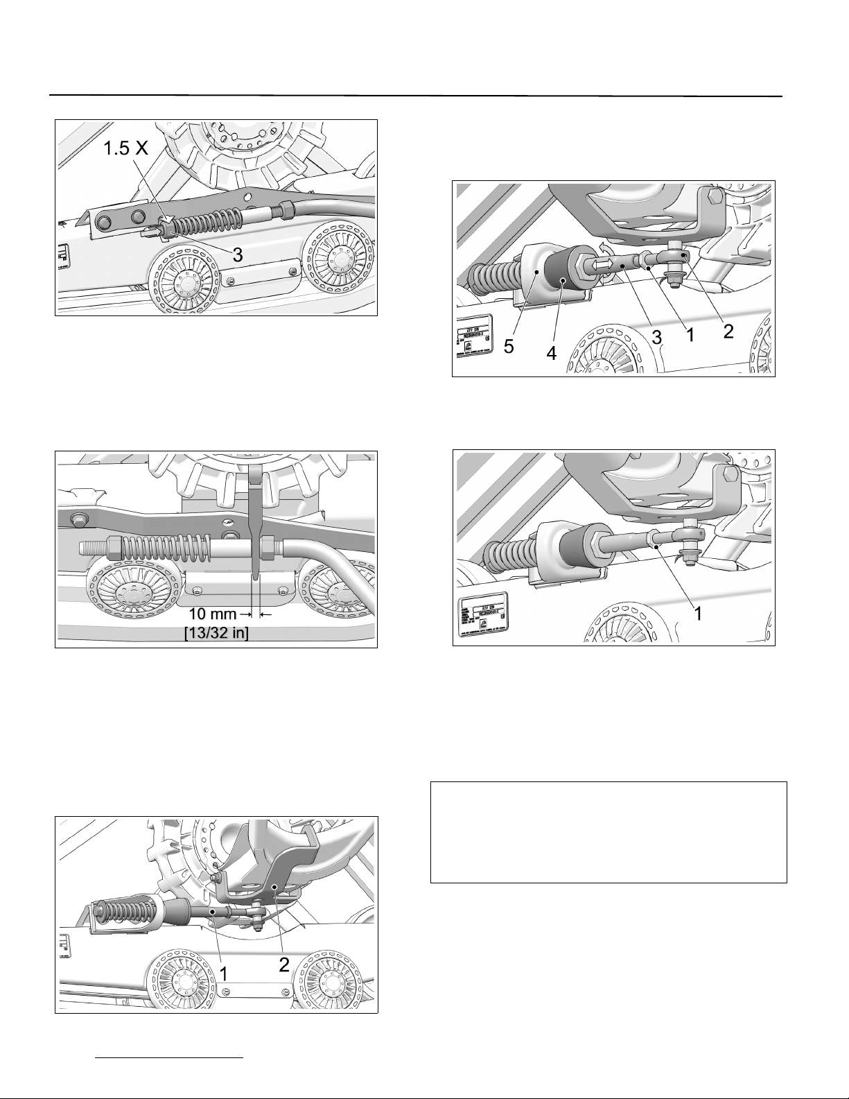
• Turn nut (3) until it comes in contact with spring,
then compress spring by turning nut 1 1/2 turn.
See Figure 11.

3
ADJUSTMENTS
Figure 11
•IMPORTANT: Double-check the 10 mm
minimum distance between nut and stabilizing
arm guide. Re–adjust as needed. Figure 12.
NOTE: Use the provided template to double-check the
adjustment.
Figure 12
INDEPENDENT SUSPENSION (IS)
• Stabilizing arm (
1
) must be attached to rear
anchor bracket (
2
) installed on vehicle. Figure 13.
NOTE: Actual Rear Anchor bracket (
2
) mounted on
vehicle may differ from the one in the illustration.
Figure 13
• Loosen jam nut (1). Turn stabilizing arm (3) to
adjust length of rod end (2) so that rubber cone
(4) applies light pressure on anti–rotation
retainer (5). Figure 14.
Figure 14
• Re-tighten jam nut (
1
) to 40 N•m [30 lb-ft] of
torque when adjustment is complete. Figure 15.
Figure 15
CAUTION: Tighten the jam nut to the recommended
torque specification. Over-tightening the nut might
damage the rod end.
NOTE: Once angle of attack adjustment on rear
systems is completed, verify once more to
confirm adjustment setting.
BASIC TUNING (Rear Track Systems):
• The adjustment is incorrect when the
stabilizing arm’s rubber cone is compressed
and deformed. The stabilizing arm’s spring is
then difficult or impossible to turn by hand.
TRACK SYSTEM REMOVAL
CAUTION: Leaving the anti-rotation anchor
brackets attached to the suspension arms, after
having removed the Track Systems, could cause
interference which might damage the vehicle.
Remove all Track System anti-rotation
components installed on the vehicle before
reinstalling the wheels.

4
ADJUSTMENTS
ALIGNMENT
Parallelism must be adjusted with the ATV on the
ground, driving the vehicle forward about 3
meters [10 ft.] and measuring toe–in distance.
Refer to Figure 16.
NOTE: Every time the measurement has to be taken,
drive in reverse, then, drive forward again for
about 3 meters [10 ft.].
CAUTION: Verify condition of the steering system
components before adjusting parallelism.
Damaged components can prevent proper
adjustment and impair proper operation of the
system.
CAUTION: Parallelism adjustment of front Track
Systems is very important and is directly linked to
longevity of System components. Users must
follow attentively the adjustment and verification
recommendations of this manual.
Figure 16
Dimension A: inside distance between front
system frames at front wheels.
Dimension B: inside distance between front
system frames at rear wheels.
A - B = 0 to 3 mm [1/8 inch]
Adjustment Method
To adjust the ATV’s steering system, first loosen
coupling rod nuts (1), then screw or unscrew the
coupling rod (2) an equal number of revolutions
on both sides of the vehicle. Re-tighten nuts when
adjustment is complete. See Figure 17.
NOTE: Starting with an open alignment setting
provides a higher degree of precision in the
adjustment.
CAUTION: Remember that some nuts have reverse
threads before loosening a coupling rod nuts (1)
on the vehicle's steering system. Make sure to
unlock the nut in the proper rotational direction.
Figure 17
NOTE: Once parallelism of front Track Systems is set,
verify once more to confirm adjustment setting.
Dimension A
must be equal to or greater than
dimension B
without exceeding
3 mm
[1/8 inch].

5
ADJUSTMENTS
Measure A
: Measure the distance inside the front
ends of the front Track System frames. See
Figures 18, 19 and 20.
Figure 18
Figure 19 (Distance inside front frames - front end)
Figure 20
Measure B
: Measure the distance inside the rear
ends of the front Track System frames. See
Figures 21, 22 and 23.
Figure 21
Figure 22 (Distance inside front frames - rear end)
Figure 23

6
ADJUSTMENTS
TRACK TENSION
• Loosen both tensioner side wheel shaft bolts
(1), enough to allow tensioner cams (2) to turn.
Figure 24.
Figure 24
• Insert ratchet wrench extension with 3/8” drive
(1) in tensioner cam’s square hole. Figure 25.
Figure 25
• Turn cam on each side and adjust tension as
close as possible to the recommended
tension. Figure 26.
Figure 26
CAUTION: Tensioner cam adjustment position
must identical on both sides of Track System.
Verify adjustment by counting at which position
each cam is set. Both positions must be the same.
• After having adjusted the tension and verified
cam positions, re-tighten both wheel shaft
bolts to 50 N-m (37 lb-ft) of torque.
• Position of Tensioner cam locking bolts:
(A) - System with 15 or 16-tooth sprockets.
(B) - System with 17 or 18-tooth sprockets. See
Figure 27.
Figure 27
• Installation direction of Tensioner cams. Figure
29 and Figure 29.
Figure 28
NOTE: With tensioner cam in position 0, the small
slots cut at 90oshould indicate 3 o’clock.
Figure 29
Correct
Wrong

7
ADJUSTMENTS
The table below shows the force (1) applied and
the deflection (2) which must occur to correctly
set track tension. Refer also to Figure 31.
BASIC TUNING
• Higher rubber track tension reduces the risk of
“derailing” and reduces drive “ratcheting”.
NOTE: Track tension set too high could cause
premature wear on system components and
is therefore not recommended.
• Lower rubber track tension provides better
traction, a smoother ride and better fuel
economy.
NOTE: The track tension testing tool shown below in
Figure 30 can be purchased through an
authorized Camso dealer. Part #2000-00-
3125.
Figure 30
Figure 31
Final Check
Ride at slow speed on a distance of about 1.5 km
[1 mile]. Re–adjust as required.
TRACK FORCE DEFLECTION
Front 13,5 kg (30 lb) 17 mm (⅝ in.)
Rear 13,5 kg (30 lb) 17 mm (⅝ in.)

1 - COMPONENT INSTALLATION
A - INSTALLATION OF REAR ANCHOR BRACKETS
* Refer to INSTALLATION GUIDELINES section entitled "Rear track systems"
B - INSTALLATION OF FRONT ANCHOR BRACKETS
* Refer to INSTALLATION GUIDELINES section entitled "Front track systems"
C - INSTALLATION OF STEERING LIMITERS (if applicable)
2 - COMPONENT ADJUSTMENT
A - ANGLE OF ATTACK
* Refer to ADJUSTMENTS section entitled "Angle of attack"
B - TRACK ALIGNMENT
* Refer to ADJUSTMENTS section entitled "Track alignment"
C - TRACK TENSION
* Refer to ADJUSTMENTS section entitled "Track tension"
D - STEERING LIMITER ADJUSTMENT (if applicable)
* Refer to INSTALLATION GUIDELINES section entitled "Front track systems"
3 - INTERFERENCE CHECK
4 - TEST RUN
5 - POST TEST RUN FINAL CHECKS
A - ANGLE OF ATTACK
* Refer to ADJUSTMENTS section entitled "Angle of attack"
B - TRACK ALIGNMENT
* Refer to ADJUSTMENTS section entitled "Track alignment"
C - TRACK TENSION
* Refer to ADJUSTMENTS section entitled "Track tension"
1.5 km (1 mile) TEST RUN
* Refer to INSTALLATION GUIDELINES section entitled "Front track systems" . ** Do not
adjust the Steering Limiter sets before having adjusted the angle of attack.
IN THE EVENT OF INTERFERENCE BETWEEN THE VEHICLE AND TRACK SYSTEM, SOME PARTS ON
THE VEHICLE MAY HAVE TO BE REMOVED OR MODIFIED, OR A LIFT KIT MAY HAVE TO BE
INSTALLED. IF APPLICABLE, SEE INSTALLATION GUIDELINES SECTION ENTITLED "COMPLETION".
CAMSO ATV R4S TRACK SYSTEMS
INSTALLATION AND ADJUSTMENT CHECKLIST
** Steps in this checklist are laid out in logical order. They should be performed in
succession to optimize the track system installation on the vehicle. **
-------------------------------------------------------------------------------------------------------------------------------------------
-------------------------------------------------------------------------------------------------------------------------------------------
-------------------------------------------------------------------------------------------------------------------------------------------
-------------------------------------------------------------------------------------------------------------------------------------------
-------------------------------------------------------------------------------------------------------------------------------------------
------------------------------------------------------------------------------------------------------------------------------------------
-----------------------------------------------------------------------------------------------------------------------------------------
Other manuals for ATV R4S
1
Table of contents
Other CAMSO Offroad Vehicle manuals