New GentleYAG Bubble Circuit Calibration Procedure Candela Corporation
8503-01-0840 Revision 01 Candela Corporation Proprietary Page 2of 4
BUBBLE CIRCUIT CALIBRATION
1. Preparing the cryogen line for testing:
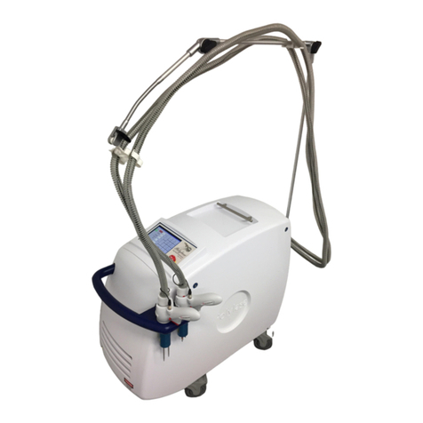
1.1. Connect any GentleYAG HP delivery system to the GentleYAG laser.
1.2. Install cryogen canister into the laser per the procedure in the Operator’s Manual.
Turn on the GENTLEYAG laser. System should display a warm-up message.
Warm-up takes approximately 20-25 minutes.
1.3. Go to Maintenance Mode in the laser.
1.4. The DCD unit must complete warm-up prior to the following tests! The cryogen is
fully warmed up when the canister pressure on the TOGGLE screen in MM mode is
between 118 and 122 PSI.
1.5. Ensure the laser is in “Standby”. While pointing the handpiece in a safe
direction, in the TOGGLE screen press the “Spray Off” button to toggle it to “Spray
On”. There should be a smooth hiss of cryogen exiting the DCD nozzle at the end of
the HP. This will purge out any bubbles in the cryogen line. Press the “Spray On”
button to toggle it to “Spray Off” to shut of the cryogen valve.
1.6. If the spray is weak or not smooth, bubbles may still exist in the line. Check to be
sure the cryogen tank is fully warmed. If tank is warm and bubbles persist, the
cryogen tank is probably low. Replace canister per procedure in the Operator’s
Manual and repeat step 1.5.
2. Handpiece Bubble Detector calibration procedure:
2.1. Go to Standby. Connect a DVM to the Bubble Sense Test Point on the CPU I/O
PCB at TP28 (+) and TP29 (-). Verify the voltage is 7.75 VDC ±0.5 VDC.
2.2. If adjustment is required open the delivery system handpiece; adjust potentiometer
R5 (WARNING: do not adjust R4, handpiece sense pot) on the GENTLEYAG HP
PCB for a DVM reading of 7.75V +/-0. 5V @ TP28 (+) and TP29 (-). Close the
handpiece and tighten the screws.
2.3. Disconnect the cryogen line from the front panel bulkhead connector. Push the
cryogen connector against a flat surface to quickly exhaust the cryogen in the
delivery system line. Verify the voltage on the CPU I/O PCB at TP28 (+) and TP29 (-
) is greater than 10.5 VDC. Also verify that HP Bubl = Yes. Turn the valve off.
2.4. Reconnect the cryogen line to the front panel bulkhead connector. Verify that within
two minutes, the HP Bubl = No and the voltage on the CPU I/O PCB at TP28 (+) and
TP29 (-) is 7.75 VDC ±0.5 VDC.
2.5. In the maintenance screen toggle the “BblTst Off” to “BblTst On” and verify the
voltage on the CPU I/O PCB at TP28 (+) and TP29 (-) is greater than 10.5 VDC and
the HP Bubl = Yes. Press the "BublTst = On" button to toggle it to "BublTst = Off".
Verify the voltage on the CPU I/O PCB at TP28 (+) and TP29 (-) goes back to 7.75
VDC ±0.5 VDC.

