Canon VB150 User manual

VB150
NETWORK CAMERA SERVER
Picture Recording User’s Guide
E
ENGLISH

Introduction
Thank you for purchasing the Canon Network Camera Server VB150 (referred to hereafter as the
VB150).
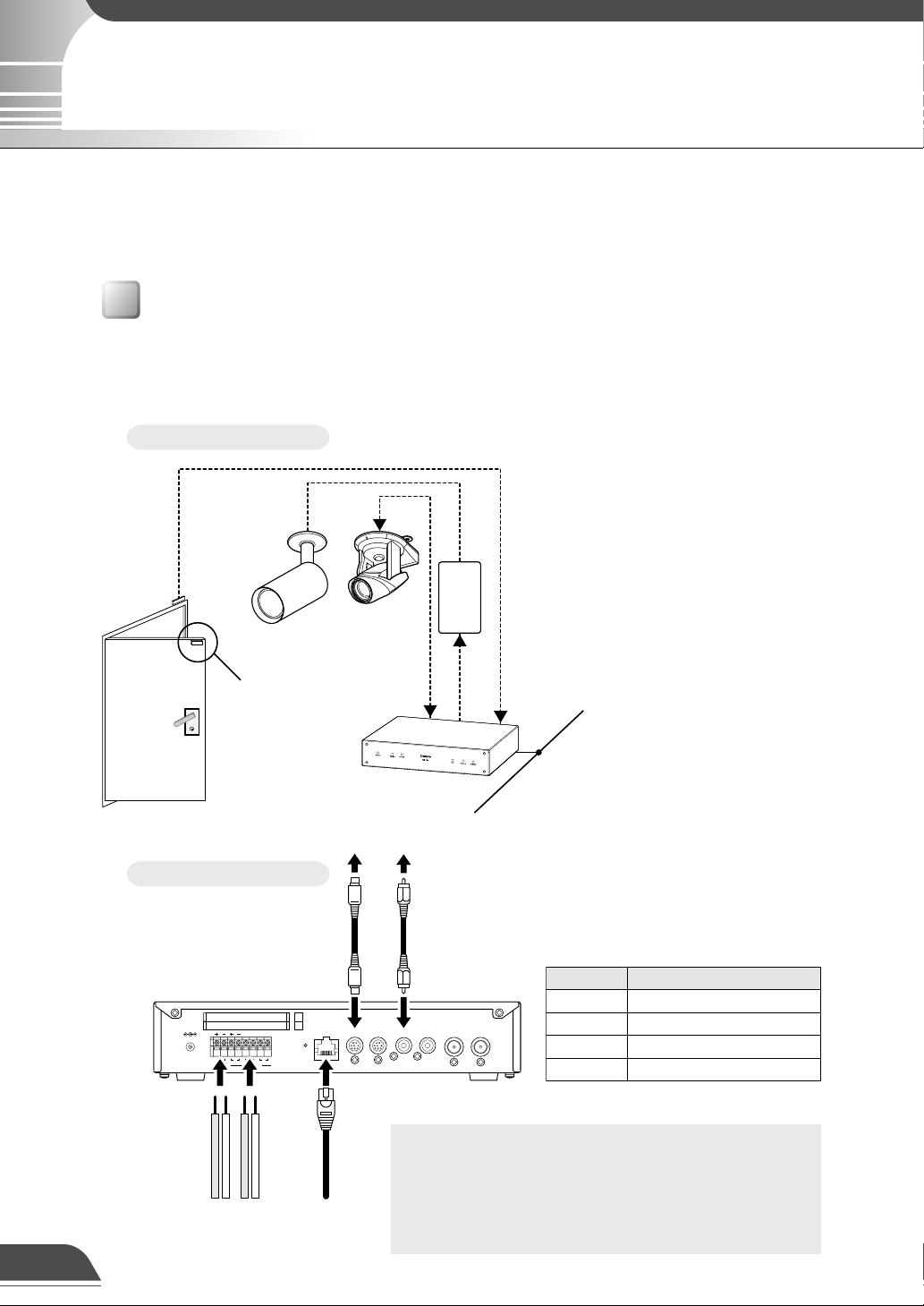
This manual describes some specific examples of the operation of the video distribution functions
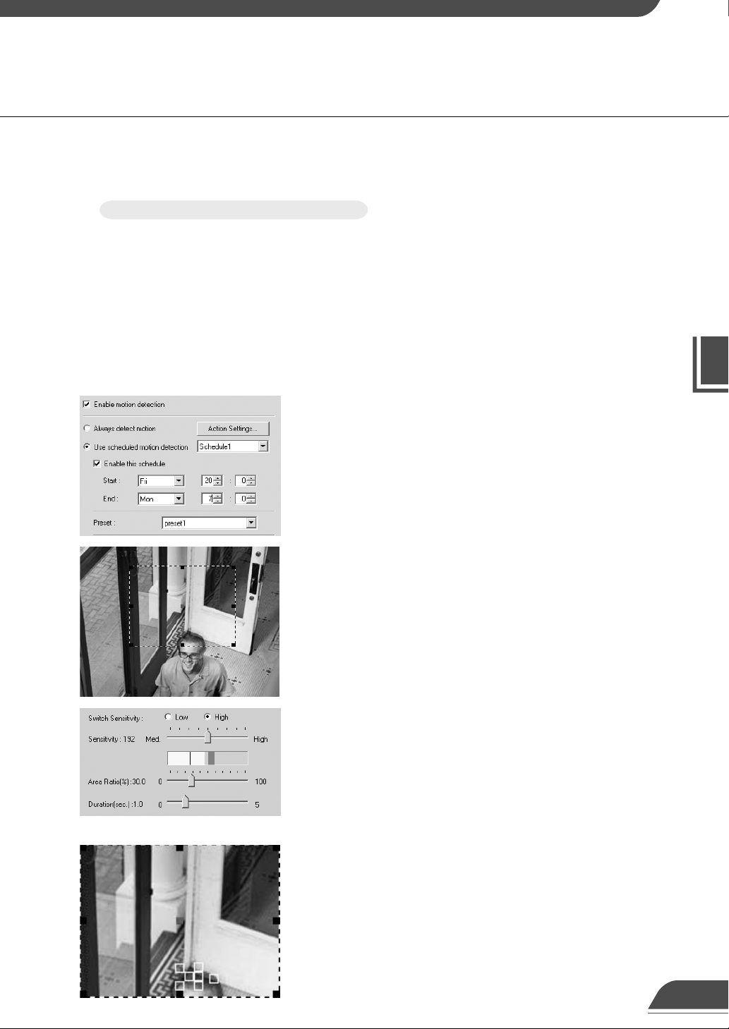
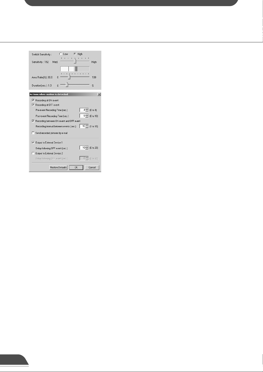
using the VB150. Pictures can be automatically recorded in response to input from an external
device or detected motion, or according to scheduled settings. The recorded pictures can then be
displayed on a website. Read this manual carefully before using the VB150 to ensure effective
operation.
Exclusion of Liability
If the Product is connected to a recording device (for example a VCR), Canon Inc. accepts no
responsibility whatsoever for any financial losses that may be incurred as a result of the loss of
recorded information or images, regardless of the internal or external cause of the loss.
Copyright Information
Video or still pictures recorded using your VB150 cannot be used in ways that infringe copyright
laws or without the consent of the owner, unless intended for personal use only.
Notes
1. The unauthorized transfer of all or any part of the contents of this Manual is forbidden.
2. The contents of this Manual are subject to change without notice.
3. Every effort has been made to ensure that this Manual is flawless. However, if you find any
oversights, please let us know.
4. Notwithstanding above, Canon accepts no liability for any results arising from the operation of
this product.
Trademark Notices
●Canon and Canon logo are registered trademarks of Canon Inc.
●Microsoft and Windows are registered trademarks of Microsoft Corporation in the United States
and other countries.
●Windows is legally recognized as Microsoft Windows Operating System.
●Java and all Java-based marks are trademarks or registered trademarks of Sun Microsystems,
Inc. in the United States and other countries.
●Other brand or product names in this manual may be trademarks or registered trademarks of
their respective companies.
Request concerning disclosure of live videos
With respect to the disclosure of live videos, we request that sufficient consideration be given to
matters of privacy and rights not to be photographed. Canon considers the following points concerning
such matters when it operates camera sites for which it has been responsible to install and operate:
-We take measures such as adding limitations on zoom magnifications so that people cannot
make special specifications.
-When videos are taken of specific buildings, interiors and the like, we install the camera only after
receiving approval from the administrator.
Please note that the operator of the camera site and not Canon has full responsibility regarding the
disclosure of live videos.
© Copyright 2004 CANON INC.
ALL RIGHTS RESERVED

Contents
Using the Still Picture Recording
Function Linked to an External Device .................. 1
Sample application in combination with
a door-opening sensor and lighting unit ............................ 1
Using the Still Picture Recording Function
with a Predetermined Schedule .............................. 3
Sample application in combination with
a lighting unit ......................................................................... 3
Using the Motion Detection Function with
a Predetermined Schedule ...................................... 5
Sample application in combination with
a warning device.................................................................... 5
Viewing and Distributing Recorded Pictures ............ 8
Viewing Recorded Pictures ....................................................... 8
Distributing Recorded Pictures............................................... 12
Using VBCollector ..................................................... 13
Installing VBCollector............................................................... 14
Starting Up VBCollector ........................................................... 16
Registering a Server................................................................. 16
Registering Tasks ..................................................................... 19
Executing and Canceling Tasks .............................................. 21
Details Displayed on the Task View......................................... 23
Starting/Stopping the Service ................................................. 24
Viewing Recorded Images ....................................................... 24
Viewing Logs............................................................................. 28
Setting the Download Capacity ............................................... 30

Dc In 13V
In Out 100/10BT
CC1
RS232C
Video In
Ethernet
CC2 V1 V2 V3 V4
Slot-A
Slot-B
12 21
A B A B
+ - + -
LAN
cable
Ethernet
RS-232C
cable
Video cable
(RCA)
External
device
output
External
device
input
Camera
Connector Attached Cable
Sensors mounted on the door
In1
Lighting unit via the power supply unit
Out1
Video cable for the VC-C4R camera
V1
Control cable for the VC-C4R camera
CC1
Using the Still Picture Recording Function Linked to an External Device
This is a monitoring system in which the lighting unit needed to take pictures switches on when the
door opens and the VC-C4R camera mounted on the ceiling captures still pictures. The equipment
shown in the figure below is connected to the terminals on the rear of the VB150 at installation.
Sample application in combination with a door-opening sensor and lighting unit
By using the “External Device Input 1/2” setting and connecting devices such as sensors and switches to
the VB150, you can construct a monitoring system that operates in response to external events. The still
pictures captured in this way are stored on a flash memory card inserted into the VB150. (→VB150 User’s
Manual P.48)
Installation Example
When the door opens and
Sensor B moves away from
sensor A, external device
input In1 generates an ON
event.
In response to this event,
Out1 is controlled to switch
on the lighting unit, pictures
of the entrance are captured
by the camera and the
pictures are stored on a
flash memory card.
VB150 Connection Example
a
Warning
●Do not directly connect the power cord for
the lighting unit to OUT1 or OUT2.
●Please also refer to page 106 of the VB150
User’s Manual.
1
VB150
Ethernet
Sensor A
Lighting unit
VC-C4R
Power
supply
unit
Lighting unit
ON/OFF
Camera control
and video images
Door opening signal
Sensor B

Picture Recording User’s Guide
Settings specified on the “Camera and Video” page (→VB150 User’s Manual P.42)
Specify the appropriate settings for the Camera 1 being used.
Settings specified on the “Preset” page (→VB150 User’s Manual P.47, 77)
Set a camera angle that records the open doorway as Preset 1.
Settings specified in “External Device Input 1/2” (→VB150 User’s Manual P.50)
●Set the recording time from 17:00 to 6:00.
●Give priority to “Recording triggered by external device”.
●Set the camera position for recording to Preset 1.
●Set the light to switch on when the door opens and to switch off 20 seconds after the door closes.
●Pictures are recorded 4 seconds before the door opens. The lights are not yet turned on.
●Record pictures for 8 seconds after the door closes.
●Record pictures at 10-second intevals while the door is open.
Sample Still Picture Recording Settings
●Delete the recorded pictures at 12:00 on the next day. In this case, delete the pictures recorded in
the morning at 12:00 on the next day, and delete the pictures recorded in the afternoon at 12:00
two days later.
2

Dc In 13V
In Out 100/10BT
CC1
RS232C
Video In
Ethernet
CC2 V1 V2 V3 V4
Slot-A
Slot-B
12 21
A B A B
+ -
LAN
cable
Ethernet
RS-232C
cable
Video cable
(RCA)
External
device
output
Camera
VB150
Ethernet
Lighting unit
VC-C4R
Power
supply
unit
Lighting unit
ON/OFF
Camera control and
video images
Connector Attached Cable
Lighting unit via the power supply unit
Out1
Video cable for the VC-C4R camera
V1
Control cable for the VC-C4R camera
CC1
Using the Still Picture Recording Function with a Predetermined Schedule
This is a monitoring system of the type used in art galleries and similar facilities in which the
exhibits are monitored in the hours they are unattended. The light switches on and still pictures
are captured at 10-minute intervals by a VC-C4R camera mounted on the ceiling. The equipment
shown in the figure below is connected to the terminals on the rear of the VB150 at installation.
Sample application in combination with a lighting unit
By using the “Schedule 1-4” setting, you can construct a monitoring system that records pictures according
to a predetermined schedule. The still pictures captured in this way are stored on a flash memory card
inserted into the VB150. (→VB150 User’s Manual P.48)
Installation Example
In accordance with the predetermined
schedule, Out1 is controlled to switch
on the lighting unit, pictures are
captured by the camera and the
pictures are stored on a flash memory
card.
VB150 Connection Example
3
a
Warning
●Do not directly connect the power cord for
the lighting unit to OUT1 or OUT2.
●Please also refer to page 106 of the VB150
User’s Manual.

Picture Recording User’s Guide
Settings specified on the “Camera and Video” page (→VB150 User’s Manual P.42)
Specify the appropriate settings for the Camera 1 being used.
Settings specified on the “Preset” page (→VB150 User’s Manual P.47, 77)
Set a camera angle that records the exhibit as Preset 1.
Settings specified in “Schedule 1-4” (→VB150 User’s Manual P.52)
●If you are not using recording triggered from an external device, leave the default priority
(“Recording triggered by external device”) unchanged.
●Set the camera position for recording to Preset 1.
●Insert a 5-second delay before recording to allow the camera to stabilize in the recording
position.
●Set the light to switch on when recording begins and to switch off 10 seconds later.
●The recording time frame is from 20:00 to 06:50. Since recording occurs daily, set the recording
start time from 0 to 6 and 20 to 23 every day of every month and choose every 10 minutes.
●Clear the “Apply the following repetition options at start time” selection.
To select more than one, click
selections while holding down the
Ctrl key. (→VB150 User’s Manual
P.52)
Sample Still Picture Recording Settings
●Delete the recorded pictures at 12:00 on the next day. In this case, delete the pictures recorded
in the morning at 12:00 on the next day, and delete the pictures recorded in the afternoon at
12:00 two days later.
4

Dc In 13V
In Out 100/10BT
CC1
RS232C
Video In
Ethernet
CC2 V1 V2 V3 V4
Slot-A
Slot-B
12 21
A B A B
+ -
External
device
output
LAN
cable
Ethernet
RS-232C
cable
Video cable
(RCA)
Camera
VB150
Ethernet
Motion
detected
Warning device
VC-C4R
Power
supply
unit
Warning device
ON/OFF
Camera control and
video images
Connector Attached Cable
Warning device via the power supply unit
Out1
Video cable for the VC-C4R camera
V1
Control cable for the VC-C4R camera
CC1
Using the Motion Detection Function with a Predetermined Schedule
In this monitoring system, a warning tone is emitted when someone enters through the door and
the VC-C4R camera mounted on the ceiling captures a still picture. The figure below shows the
equipment that is installed and connected to the rear panel on the VB150.
Sample application in combination with a warning device
By running the motion detection function according to a schedule, you can construct a monitoring system
that records pictures in accordance with a preset schedule and that operates in response to variations in
the video image from the area covered by the camera. The recorded pictures are stored on a flash memory
card inserted into the VB150. (→VB150 User’s Manual P.82)
Installation Example
When the camera shooting the area
inside the door detects a change, an
ON event occurs.
In response to that event, a warning
tone is issued by the Out1 control, the
camera shoots a picture of the
entrance and the pictures are stored
on a flash memory card.
VB150 Connection Example
5
a
Warning
●Do not directly connect the power cord for
the warning device to OUT1 or OUT2.
●Please also refer to page 106 of the VB150
User’s Manual.

Picture Recording User’s Guide
Settings specified on the “Camera and Video” page (→VB150 User’s Manual P.42)
Specify the appropriate settings for the Camera 1 being used.
5Settings specified on the “Preset” page (→VB150 User’s Manual P.47, 77)
Set the camera angle for the area just inside the door as Preset 1.
Settings specified in the “Motion Detection Setting Tool” (→VB150 User’s Manual P.82)
Sample Still Picture Recording Settings
●Select “Enable motion detection”.
●Select “Use scheduled motion detection”.
●Set weekend monitoring as the time for picture recording,
as follows:
Schedule 1 --- 20:00 Friday to 7:00 Monday
●Set the “Preset” to be used for shooting to Preset 1.
●To set the level of motion detection sensitivity that will
trigger an ON event, shoot a simulation of the actual event
and reproduce the amount of change that registers as an
incursion. In this situation, in order to capture the picture
variation that is recognized as the door opening and
someone entering the room, first position the motion
detection frame on the center of the door.
●Next, set the parameters for “Motion detected”.
To ensure that the event is not triggered by unrelated
lighting changes or small movements, set the “Duration”
parameter so that picture changes lasting a second or less
are ignored and then set the “Area Ratio” parameter so
changes that occupy 30% or less of the total picture are
also ignored.
●Then reproduce the conditions for someone entering the
room and check that the change in the picture is captured
by the red rectangle in the viewer. If the change is not
recognized, increase the sensitivity.
6

●Once the red rectangle in the viewer reliably captures the
intruder, check that the peak display in the detection
indicator gives a “Motion detected” result. If there is no
“Motion detected”, adjust the sensitivity, area ratio and
duration settings.
●Record the 4 seconds of video that precedes the “Motion
detected” event.
●Record 8 seconds of video after the “Motion detected”
event.
●Between “Motion detected” events, record pictures at 10
second intervals.
●Set the parameters so that a signal is sent to the warning
device at the same time as the “Motion detected” event
and discontinued 10 seconds later.
Operation of the Motion Detection Function Using a Schedule
7

Picture Recording User’s Guide
Viewing and Distributing Recorded Pictures
Use your Web browser to access the following
URL:
http://192.168.100.1/sample/lookup/
*Enter the actual IP address set for the VB150.
(→VB150 User’s Manual P.36)
The “Sample Page for the Retrieval of
Recorded Pictures” shown at left appears.
Click the “Specify capture period with text”
link if you want to enter numbers to specify
the recording period to be searched, or click
the “Specify capture period with menu” link to
select the recording period from a menu.
Viewing Recorded Pictures
You can search and view recorded pictures by accessing the “Sample Page for the Retrieval of Recorded Pictures”. You can
search by trigger, by camera or by time interval from your browser and view pictures as images or as a pseudo-animation.
You can also distribute recorded pictures directly to users so that they can search and view the pictures in the same way.
When you select “Specify capture period with
text”, the Conditions for Image Retrieval
screen appears in window 1at left.
●
Select either
“
External Device Input
”
,
“
Schedule
”
or
“
Motion Detection
”
as the
“
Trigger
”
. External Device Input 1 and 2
correspond to the “External Device Input 1/2
”
parameter on page 50 of the VB150 User’s
Manual, schedule 1-4 corresponds to the
“
Schedule 1-4
”
parameter on page 52 and
motion detection corresponds to the Motion
Detection Setting Tool on page 82. Use the
“
any” option to search all the options for the
respective parameter.
●
In
“
Camera
”
, specify the camera number to be
searched. Select “any” to search all the cameras.
●In “Capture Period”, enter the date and time the pictures were captured.
Example 1/200204191830-20020420010530
Searches from 18:30:00 on April 19, 2002 to 01:05:30 on April 20, 2002.
Example 2/20020419-[blank]
Searches from 00:00:00 on April 19, 2002 to the present.
Example 3/[blank]-20020420
Searches from the oldest recorded pictures to 23:59:59 on April 20, 2002.
When you specify the search condition and click the [Retrieve] button, a list of the recorded dates and
times that meet those conditions appears in window 2. When you click on one of the listed items, the
corresponding picture and capture information appear in window 3.
1
23
8

If you select “Specify capture period with
menu”, the Conditions for Image Retrieval
screen appears in window 1at left.
●
Select either
“
External Device Input”,
“
Schedule” or
“
Motion Detection” as the
“
Trigger”. “External Device Input1 and 2
correspond to the
“
External Device Input 1/2”
parameter on page 48 of the VB150 User’s
Manual, schedule 1-4 corresponds to the
“
Schedule 1-4” parameter on page 50 and
motion detection corresponds to the Motion
Detection Setting Tool on page 80. Use the
“
any” option to search all the options for the
respective parameter.
●
In “Camera”, specify the camera number to be
searched. Select “any” to search all the cameras.
●
In
“
Capture Period
”
, select the date and time
the pictures were recorded.
When you specify the search condition and click
the [Retrieve] button, a list of the recorded dates
and times that meet those conditions appears in
window
2
. When you click on one of the listed
items, the corresponding pictures and capture
information appear in window
3
.
By clicking “animation” in the list display, you
can view all the retrieved pictures in the list
continuously as a pseudo-animation.
Use the slider to vary the speed of the
animation.
Start/Stop button
Displays the position of the
current picture number relative
to the total number of pictures.
Drag to reposition.
1
23
e
Tip
Customize the Conditions for Image Retrieval page to suit the actual operation.
Click the right side of the picture to display
the next picture, and click the left side to
display the previous picture.
9

Picture Recording User’s Guide
List format. Specify “html” to specify a list display page, or “anim” to specify a page
for SnapAnimator. If this parameter is omitted or an undefined value is specified,
“html” is used.
type
Specifies the HTTP server and the IP address of the HTTP server. If this parameter
is omitted, the IP address of the client side network interface is used*.
server
Target frame name for list display. Mandatory when a multi-frame configuration is
used to construct the picture search page.
target
Language used to display the desc command attribute information. Specify
“
english
”
for
English-language display and
“
japanese
”
for Japanese-language display. The default
value is
“
english
”
. When an undefined value is specified, the default value is used.
locale
Specifies the range for the search results. Specify an integer of 0 or more for either.
Of the list of recorded pictures that satisfy the search criteria, the list displayed
excludes the number of items specified by the skip parameter from the beginning of
the list and includes items up to the limit imposed by the limit parameter. If these
parameters are omitted or erroneous values are specified, skip is set to 0 and limit to
100. If limit is set to 0, no limit is applied.
skip/limit
Specifies the trigger that governs the main cause of picture recording. A setting of i0
restricts any external device input, and i1 and i2 restrict external device input to
inputs 1 and 2. A setting of s0 restricts any schedule setting, and s1, s2, s3 and s4
restrict schedule setting to settings 1,2,3, and 4. m is motion detection. If this
parameter is omitted, or an undefined value is specified, the trigger is unrestricted.
tn
Parameter Name Details
Camera number used for recording. Specify a value from 1 to 4 as the camera
number. If this parameter is omitted or an undefined value is specified, the camera
number is unrestricted.
cn
Start time for the recording period. Specify a setting using the “yyyymmddHHMMSS”
format (yyyy: year; mm: month; dd: day; HH: hour; MM: minute; SS: second). If this
parameter is omitted or an erroneous value is specified, the start time for the
recording period is unrestricted.
A part of the mm, dd, HH, MM, SS parameter can be omitted. The default settings
are 01 for mm and dd, and 00 for HH, MM and SS.
ts
End time for the recording period. The specification format and the handling of
omitted or erroneous parameters is the same as for ts. A part of the mm, dd, HH,
MM, SS parameter can be omitted. The default settings are 12 for mm, 31 for dd, 23
for HH, and 59 for MM and SS.
te
Pictures Search CGI
The pictures search CGI includes the “enum” command to generate a list of recorded pictures that
satisfy the search criteria, the “desc” command to generate the video data display page, and the
“data” command to retrieve the video data.
enum Command
The “enum” command is used to generate a list display page for the search page and to
generate a page for SnapAnimator. The items shown in the recorded picture list generated by
the “enum” command are displayed in order of the time they were recorded.
■enum Command Parameters
*This is a function that corresponds to address replacement using <_I_P_A_D_D_R_>.
However, you cannot specify <_I_P_A_D_D_R_> itself.
Viewing and Distributing Recorded Pictures
10

Specifies the video data. This is the video data file name excluding the “.jpg”
extension and is specified using the “yyyymmdd/HHQQ/HHMMSSCC” format. This
parameter can not be omitted.
b
Specifies the HTTP server and the IP address of the HTTP server. If this parameter
is omitted, the IP address of the client side network interface is used*.
server
Language used to display the desc command attribute information. Specify “english”
for English-language display and “japanese” for Japanese-language display. The
default value is “english”. When an undefined value is specified, the default value is
used.
locale
Parameter Name Details
desc Command
The “desc” command is used to generate a video display page. The video display page uses
HTML text for the video display area and attribute display area, and uses the “data” command
described below to retrieve the video data.
■desc Command Parameters
data Command
The “data” command retrieves video data. The parameters only specify the video data and the
format is the same as the b parameter for the desc command. Specify the data directly as
“data?yyyymmdd/HHQQ/HHMMSSCC” with no parameter name. (QQ = every 15 minutes,
indicated as 00, 15, 30, or 45.)
11
*This is a function that corresponds to address replacement using <_I_P_A_D_D_R_>.
However, you cannot specify <_I_P_A_D_D_R_> itself.

Picture Recording User’s Guide
Distributing Recorded Pictures
Distributing pictures that have been recorded
If you forward a picture (JPEG) recorded with the Schedule recording function using FTP and
copy it, or remove the flash memory card, download the picture to a PC and embed the picture in
a Web page, you can create a still-picture distribution page.
Distributing pictures in SnapAnimator display format
Pseudo-animations (→P.8) are created using the SnapAnimator applet. The following example is
a SnapAnimator description in a HTML source. Customize the description between <APPLET>
and </APPLET> to enter the picture in the place you want to paste it.
* The underlined text is an IP address. Enter the actual IP address set for the VB150.
Parameter
Description
image0 Specifies the URL of the picture file. When specifying multiple picture files,
specify them successively as image1, image2, etc.
Specifies the time at which image0 was taken.Written in the “Y/M/D H:M:S”
format.
■SnapAnimator parameters
time0
The above example was generated using an emum command for the picture search CGI. By using this
description to properly specify the image0 and time0 parameters, you can also create an picture distribution
page that displays any still pictures (JPEG) you have on hand as pseudo-animations. In this case, enter the
time stamp that corresponds with the name of the picture file that you want to display in the double-underlined
portion and enter the imageX and timeX parameters for the number of pictures which you want to display.
<APPLET CODEBASE="http://192.168.100.1/-wvdoc-01-/SnapAnimator/"
code="SnapAnimator.class"
archive="SnapAnimator.zip" width=320 height=300>
<PARAM NAME=cabbase VALUE="SnapAnimator.cab">
<PARAM NAME=image0 VALUE="http://192.168.100.1/-vbidb-/data?20000102/
0300/03040507">
<PARAM NAME=time0 VALUE="2000/01/02 03:04:05">
<PARAM NAME=image1 VALUE="http://192.168.100.1/-vbidb-/data?20000216/
1000/10100713">
<PARAM NAME=time1 VALUE="2000/02/16 10:10:07">
<PARAM NAME=image1 VALUE="http://192.168.100.1/-vbidb-/data?20000316/
0100/01100815">
<PARAM NAME=time2 VALUE="2000/03/16 01:10:08">
...
</APPLET>
Viewing and Distributing Recorded Pictures
12

Downloaded image displays
Pictures recorded with the VB150’s
picture recording function
Pictures periodically collected
according to the task
Using VBCollector
VBCollector is used to view pictures recorded by the VB150. With VBCollector, you can collect and display still
pictures recorded by the VB150 based on inputs from an external device, motion detection or schedules.
VBCollector accesses the VB150 at specific times expressed in units such as dates, weeks, or months, and then
downloads the recorded pictures. Since the recorded pictures are saved one after another in the PC on which
VBCollector is installed, pictures can still be securely saved when the allowable limit on the number of pictures that
the VB150 can record and save has been exceeded. Downloaded images can also be easily viewed in the Web
browser. Information related to task execution can also be recorded in a log.
VC-C4
COMMUNICATIONCAMERA
f:4-64mm1:1.4-2.8
VB150
Flash memory card
13

Picture Recording User’s Guide
c
Note
●Check the operating environment (→VB150 User’s Manual P.20) before
starting installation.
●VBCollector cannot be installed on a PC where MV Ver. 2.0 or later version
is already installed.
To Install...
If any other applications are running, please exit
them before installation. Please also be sure to
close the Windows Service Panel.
Load the supplied CD-ROM into the CD-ROM drive.
Double-click “CltSetup.exe” on the CD-ROM to start
up the installer. Click the Next button.
2If you agree to the clauses in the licensing
agreement, click Yes.
3Specify the target directory for the installation and
click the Next button.
If you have no special directory preference, just click
Next.
1
4Specify the menu name to be registered in the
Program menu of the Start button, then click Next.
Installing VBCollector
14

5Check the settings and items you have selected thus
far, and click Next to confirm. The installation will
proceed by copying files and making registry
settings, etc.
Click Finish to complete the installation.
6
When installation is complete, “VBCollector Task
View” is added to the Start menu.
15

Picture Recording User’s Guide
VBCollector is started up by choosing it from Start menu.
To Start Up VBCollector...
Choose [Program]-[WebView Livescope]-[VBCollector
Task View] from the Start menu to start up VBCollector.
Starting Up VBCollector
To use VBCollector, the network camera server (hereafter referred to as “server”) from which the
VBCollector downloads pictures must be registered.
Registering a Server
To Add a New Server...
To add a server, choose Add from the Server menu,
or click the Add button on the Server List dialog box
that appeared when Edit from the Server menu was
selected.
1
Adding a server
Add a new server to which VBCollector will download pictures.
Using VBCollector
16

2Enter the various fields and click OK.
■Server Name
Assign a name for recognizing the Server.
■Image Directory
Enter the name of the directory where downloaded images are to be saved, or click Browse to select a
directory folder. Refer to the next page for how to download images to a shared folder on the network.
Delete images on the server
When this check box is selected, pictures that VBCollector downloaded from the server will also be deleted
from the server.
■Server information
Host Name (→VB150 User’s Manual P.38)
Specify an IP address or a host name.
HTTP Port (→VB150 User’s Manual P.57)
Enter the HTTP port number set in the server. (The default setting is 80).
Administrator Account (→VB150 User’s Manual P.37)
Enter an administrator account registered in the server.
Administrator Password (→VB150 User’s Manual P.37)
Enter the administrator password registered in the server.
Settings Page URL (→VB150 User’s Manual P.37)
Enter the “Path” to the setting title page set in the server.
■Proxy
Use Proxy Server
Select if connecting through a proxy server.
Host Name
Specify a host name or IP address for the proxy server.
Port
Enter a port number for the proxy server (The default setting is 8080).
■PPP
Use PPP connection
Select if connection will be established by dialing up.
PPP Connection Name
Select a phone number from the phone book entry. A dialup network will need to have been installed and
the phone number will need to have been registered in the phone book.
Account
Enter the PPP account to be used for the dialup connection.
Password
Enter the PPP password to be used for the dialup connection.
17
Other manuals for VB150
3
Table of contents
Other Canon Network Hardware manuals

Canon
Canon VK-16 v2.1 Use and care manual

Canon
Canon VK-16 v2.1 User manual

Canon
Canon Vb-C60 - Ptz Network Camera User manual

Canon
Canon VK-16 v2.0 Use and care manual

Canon
Canon Vb-C60 - Ptz Network Camera User manual

Canon
Canon C50FSi - VB Network Camera User manual

Canon
Canon VB150 User manual

Canon
Canon VK-16 v2.1 User manual