Canopy Factory 25757 User manual

05-25757 11/28/03 Pg.1
10' x 20'
All-Purpose Canopy
Installation
Instructions
Please read instructions
COMPLETELY before assembly.
DO NOT RETURN
PRODUCT TO
THE STORE
Missing Parts,
Help with Assembly
Need Replacements,or
Please Contact
Customer Service:
1-800-524-9970
North American
Outdoor Products
13 Wood Street • West Haven
CT 06516
www.outdoorfactory.com
.
12 13001
13002
13003
13004
3-Way Frame Connectors
4-Way
F
r
ame
Connectors
White Valance Cover
41" Swedged Tube
Base Feet
White Bungee Cords 10066
41" Straight Tube
41" Straight Tube with extra hole
for top of leg
25 3/4" Swedged Tube
40" Swedged Tube for bottom of leg
6
3
1
10063
10064
10072
6
24
Description Qty Part #
6
6
6
10075
12 13005
WARNING!
Use CAUTION when assembling this unit. Manufacturer recommends the
use of safety goggles during assembly. Bungees are under extreme
tension and may snap out of your hand and cause injury. Be aware of
poles over your head during assembly that may not be secured, and
could fall and cause injury.
Patent NO. ZL 02 2 160 11.6 and other patents pending.
Model #25757
The Canopy
Factory
Step 1
Step 2
Step 4
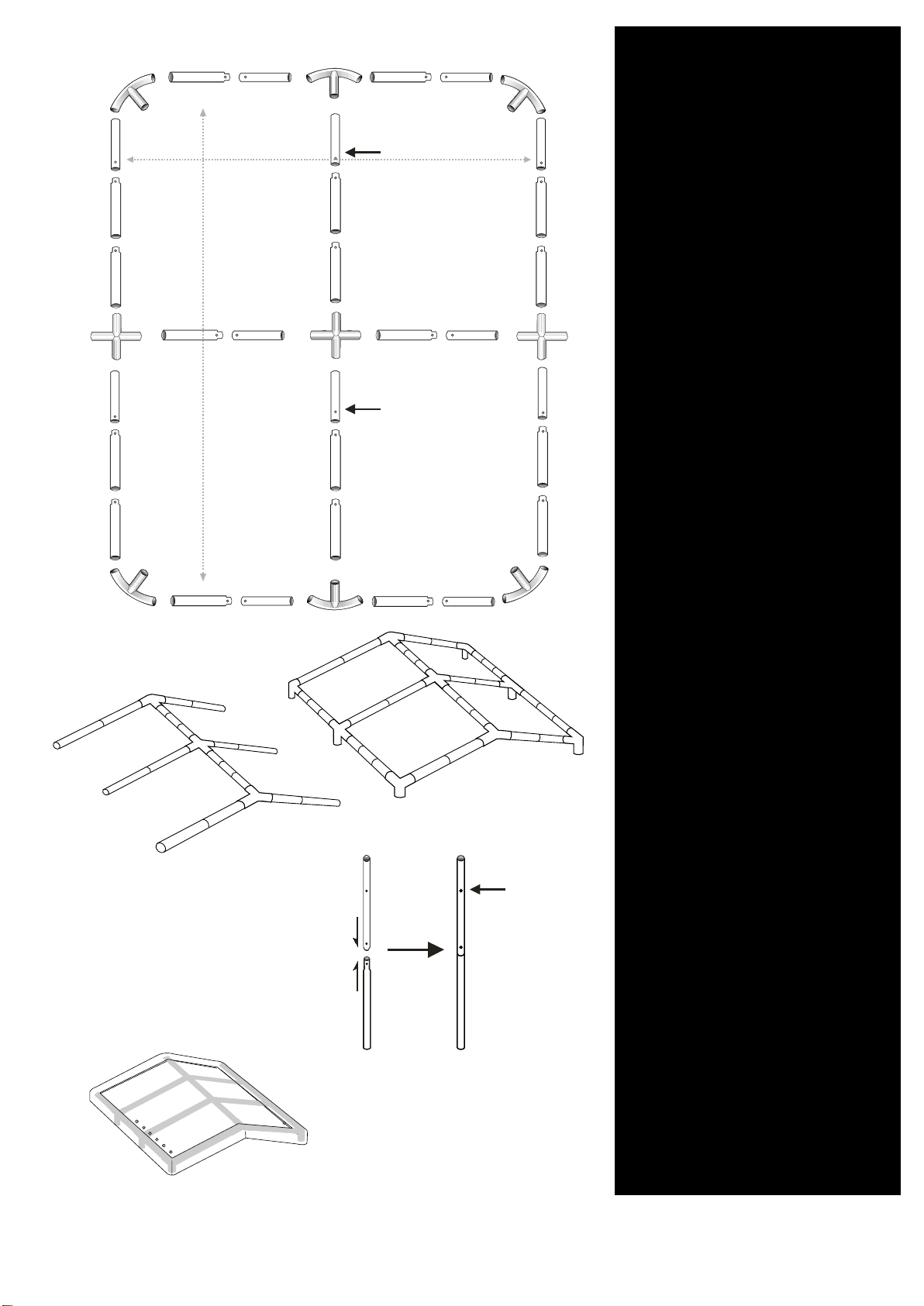
EASY FRAME LAYOUT
First, layout all the frame parts
exactly as shown in diagram 1.
Next, combine all the parts
listed below to form the frame,
starting with the center peak,
and then assemble each side.
12 - #13001 (41" Straight Tubes)
12 - #13005 (41" Swedged Tubes)
6 - #13003
(25 3/4" Swedged Tubes)
6 - #10063
(3-Way Frame Connector)
3 - #10064
(4-Way Frame Connector)
13001
13001
13005
13005
13003
10063
10064
10063
Place cover over frame with
the grommetsfacing downward
allowing the valance to wrap
around and cover the eaves of
the frame.
#13002 to leg
Straight tube
#13004
Top leg
of tube
FACE ALL PUSH
BUTTONS
DEVICES DOWN
FACE ALL PUSH
BUTTONS
DEVICES DOWN
05-25757 11/28/03 Pg.2
Swedged tube
Diagram A
Diagram D
Diagram B
Diagram C
Diagram E
Note:
Face all push button
devices, located on the metal
tube, in a downward direction.
FRAME ASSEMBLY
Step 3
Connect one each of part
# 13002 and # 13004 then set
set them aside for now.
ubes with6 - #13002 (41" Straight T
6 - #13004 (40" Swedged Tubes for
extra hole for top of leg
bottom of leg)
)
(See Diagram D)
POLE ASSEMBLY
Note: Face all push buttons
in a downward direction. (They
are located on the metal tube)
05-25757 11/28/03 Pg.2
(See Diagram A)
(See Diagrams B & C )
(See Diagram E)

ATTACHING LEGS
For this step you will use the
six leg poles you put together
in step 1.
First you will use part #13002
with the pre-drilled hole at the
top, insert the center leg on
one side, and then do the same
for the corner legs. Repeat this
procedure for the other side.
Now you can secure the legs
to the side bend connectors
with push buttons. Insert the
leg extensions onto the bottom
of the legs.
(See Diagram F)
SECURING COVER
Insert the cord of the bungee-
ball through the grommet, around
the eaves, and then the ball.
When all 4 corners are secured,
work from side to side to get an
even fit. If bungee cords are too
loose, you can double wrap them
around the eaves.
USE CAUTION WHEN
ATTACHING BUNGEE CORDS,
THEY CAN SNAP OUT OF
YOUR GRIP AND MAY CAUSE
INJURY. .
#13002
#13004
Working from the inside of the cover, you can hide the bungee
balls from the outside, giving the canopy a cleaner look.
COVER
TwistTight TM
A
Cover S-Hooks are
designed to hold the
front & back of the cover
tightly in place.
1. Hook one onto each
of the INSIDE of the
cover legs.
2. Adjust the drawstring
evenly on each side of
the canopy by pulling
the drawstrings on each
end of the cover at the
same time
3. Secure rope to "S" Hook
4. The next step will
feature our new "TwistTight"
procedure to fit the cover
snugly.
1. To get your cover to fit
snugly over the frame, "twist"
each corner leg pole equally
until the cover becomes very
tight. (diagramA). Make sure to
line up the hole in the top of the
leg with the hole in the corner
side bends.
2. To keep the leg in place,
wrap the bungee cord around
the cross rail, insert "S" Hook
into lined up hole of leg pole
and 3-way connector. This
will prevent the leg from
"untwisting". Do this for each
corner.
3. Now you are ready to
"BUNGEE" the cover to the
rafter poles. Keep bungee ball
on the inside of the unit for a
cleaner look.
BASE FEET
Insert the Base Feet Plates onto
the bottom of the legs.
Twist
tube Twist
tube
Twist tube this direction
to tighten cover
05-25757 11/28/03 Pg.3
Manufacturer's Suggestion:
When you take your unit down for the
season, we recommend leaving the poles
assembled so that the next time you put
up the unit it will be easier to construct.
Diagram F
Diagram G
Diagram H Diagram I
Diagram J
Step 6
Step 7
Step 8
WARNING!
(See Diagram J)
(See Diagram G, H, & I)

CARE AND CLEANING
INFORMATION
DO NOT expose the canopy to open fire or flame by using BBQ
grills or smoking under the canopy. DO NOT use harsh
abrasives, bleach or cleansers.
Cover can be easily cleaned with mild soap and water.
North American Outdoor Products DOES NOT guarantee and will
not be held be responsible for any canopy exposed to and / or
damaged by conditions of snow, ice, heavy rain, or high wind
under ANY circumstance. We also will not be responsible for any
other damage caused by the canopy or to the canopy. Therefore,
ANCHORING OF CANOPY
EFFECTS OF STRONG
WINDS, SNOW OR ICE
Our canopies are designed to offer protection from damage
caused by the sun, light rain, tree sap, and birds.
properly or securely will fly away and we will not be held
other outside structure.
THIS IS A TEMPORARY STRUCTURE AND IS NOT
RECOMMENDED AS A PERMANENT STRUCTURE.
or severe weather front is approaching. We suggest you contact
your insurance carrier for information just as you would for any
After assembly your structure must be anchored to prevent
Periodically check the stakes or anchors to ensure stability of
screw-in anchors and cable attached to each leg. Mobile home
anchors will also work. Any canopy that is not anchored
PROPER AND IMPROPER
05-25757 11/28/03 Pg.4
the unit, especially following exposure to the elements such as
high winds or heavy rain. The preferred anchoring system uses
kits, walls, tubes, as well as additional covers, and other
accessories. Any item purchased is shipped factory direct,
thus ensuring consistent quality of our products.
For more information, please contact our customer service
department Mon-Sat. 8:30 AM - 5PM EST.
damage. PROPER ANCHORING IS YOUR RESPONSIBILITY .
North American
Outdoor Products
13 Wood Street • West Haven
CT 06516
www.outdoorfactory.com
Missing Parts,
Help with Assembly
Need Replacements,or
Please Contact
Customer Service:
1-800-524-9970
Replacement parts are available. We offer several anchoring
IMPORTANT!!
OUR GUARANTEE
PLEASE READ
CAREFULLY
responsible for a canopy that has blown away.
you will need to remove the cover when you know that a strong
e
EFF
Other Canopy Factory Tent manuals


