Canyon Hydro M300 Pico Owner's manual

M300 Pico Hydro System
Installation - Operations - Maintenance
Version 2.0.0.1

Page 2

Page 3
Table of Contents
1. Introduction 5
2. Theory of Operation 7
3. M300 System Components 9
3.1 M300-30 Turbine-Generator Assembly 10
3.2 M300-60 Turbine-Generator Assembly 11
3.3 Control Panel & Motorized Valve 12
3.4 Component Details 13
4. Equipment Installation 17
4.1 Parts List 18
4.2 Additional Materials Required 19
4.3 Additional Materials Recommended 21
4.4 Connected Devices 22
4.5 M300-30 Recommended System Layout 23
4.6 M300-60 Recommended System Layout 24
4.7 Installation Procedure 25
5. System Operation 29
5.1 Initial System Startup 30
5.2 System Shutdown 34
5.3 System Startup 35
6. Maintenance 37
6.1 System Maintenance 38
7. Appendix 39
7.1 Planning Your System 40
7.2 MHC2500 Control Panel Charge Theory 44
7.3 MHC2500 Control Panel Menus 46
7.4 Equipment Drawings and Performance Curves 48

Page 4

Page 5
1. Introduction
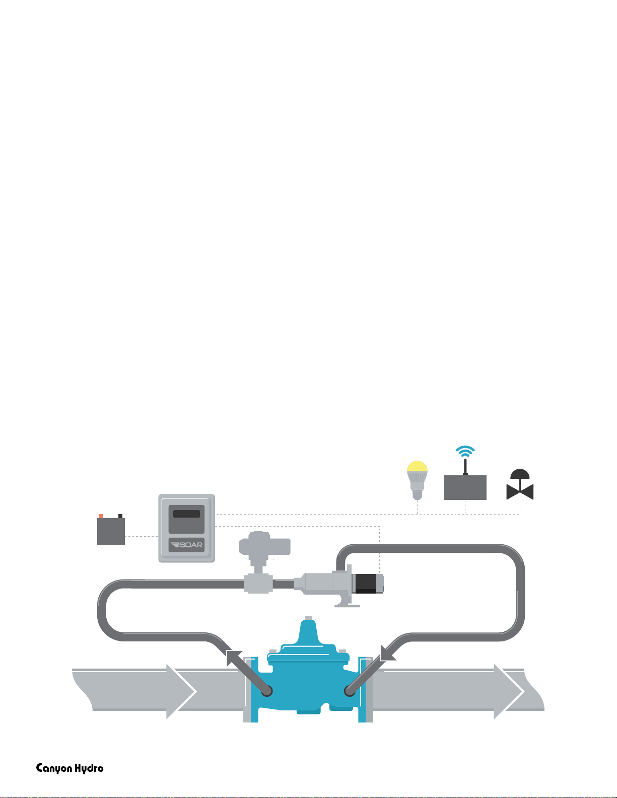
The M300 Pico-Hydro is a water-driven power generation and storage system.
Commonly installed in remote or unpowered locations the M300 system provides
electrical power to run a variety of equipment. Power generated is often used
for data aquisition and transmission and powering local devices.
Common equipment powered by the M300 Pico-Hydro system include Remote
Terminal Units (RTUs) for SCADA systems, pressure or ow control devices, radios,
blowers, fans, sump pumps, and LED lighting.
Unlike wind or solar, the M300 Pico-Hydro operates efciently in any kind of
weather and can be installed out of sight in secure locations. Because power
generation is readily available at all times smaller energy storage components
are required thereby reducing system cost.
This manual is intended to help with installation, operation, and maintenance
operations for the M300 Pico-Hydro System.

Page 6

Page 7
2. Theory of Operation
The M300 Pico Hydro System generates power by recovering energy at water
network pressure drop locations. Water networks frequently use pressure
reduction valves (PRVs) to reduce water pressure for water delivery operations.
The Pico Hydro is installed in parallel with a pressure reduction valve and
generates electrical power from the pressure differential.
The M300 system works by diverting a small portion of the ow around the
PRV and into a hydroelectric turbine. Flow passes through the turbine and is
converted from hydraulic energy into electric energy.
Generated electricity is sent to the control panel which provides system
monitoring and control. The control panel intelligently distributes power to
connected devices and a battery bank. Charge level is monitored and power
generation is automatically matched to demand. Power output is regulated by
a motorized valve which precisely modulates generation.
The battery bank’s stored power allows for uninterrupted operation of the
connected devices in times of diminished water ow and permits short term high
power consumption periods such as surge loads.
RTU

Page 8

Page 9
M300-30 or M300-60 Turbine Generator Assemblies
Converts hydraulic energy into electric energy
MHC2500 Control Panel & Motorized Valve
Provide system optimization and generation control
Low Voltage Battery Bank
Acts as a system ballast and stores energy for later use
3. M300 System Components

Page 10
15-32 PSI Net Head Applications
1.25 NPT Inlet / 1.50 NPT Discharge
1/2” Electrical Conduit Connection
300-Watt Maximum Output
M300-30 Turbine-Generator
11 x 10 x 9 Inch Overall Size
3.1 M300-30 Turbine-Generator Assembly

Page 11
27-73 PSI Net Head Applications
1.25 NPT Inlet / 1.25 NPT Discharge
1/2” Electrical Conduit Connection
300-Watt Maximum Output
15 x 7 x 4 Inch Overall Size
M300-60 Turbine-Generator
3.2 M300-60 Turbine-Generator Assembly

Page 12
Provides system monitoring and control
Displays current operation information
Dynamically matches generation to load
Maintains optimum battery charge levels
Ensures battery bank is not depleted
12/24 VDC compatible
12 x 10 x 6 Inch Enclosure Size
MHC2500 Control Panel Modulates flow through system
Operates on 4-20 mA signal
1.25 NPT Connections
Motorized Valve
3.3 Control Panel & Motorized Valve

Page 13
3.4 Component Details
3.4.1 M300-30 & M300-60 Turbine-Generator Assemblies
Both the M300-30 and M300-60 Turbines are reaction style hydro turbines.
Reaction style turbines develop torque by reacting to a fuild’s pressure.
The amount of torque generated by a reaction style turbine is proportional to
the pressure differential across it. The power generated by the turbine is a result
of both the torque generated and the shaft speed.
In a water network application the pressure differential across the turbine is set
by the PRV in parallel with the system. The PRV’s upstream and downstream
pressure settings will dictate those of the turbine.
The pressure differential across the turbine determines the maximum power
output of the turbine as well as the ow rate through the turbine.
Both the M300-30 and M300-60 Turbines have a maximum rated output of
300-watts even though they operate across different pressure ranges. The M300-
30 Turbine operates at lower pressure and passes more ow. The M300-60 Turbine
operates at a higher pressure differential and requires less ow. This is reected in
the turbine performance charts located in the appendix.
Choosing the correct turbine for a particular application is done by evaluating
the available net pressure differential (upstream pressure - downstream
pressure). It is also important to consider the turbine’s required ow rate to
ensure adequate ow is available.
The maximum pressure differential across each of the turbines must be within
their rated limits. Exceeding the rated pressure differentials can cause the
turbines to over power the generator, damaging it.
CAUTION: Over powering the turbine-generator will result in permanent
damage to the equipment and must be avoided.
For applications in excess of each turbine’s rated operating range it is possible
to install a small pressure reducing valve in line with the turbine-generator,
limiting the incoming pressure to the turbine. Consult the in line PRV diagrams in
the appendix for further details.
For applications where ows drop below the turbine’s rated ow or where ows
diminish completely a small pressure reducing valve can be placed after the
system to maintain downstream pressure. Consult the in line PRV diagrams in the
appendix for further details.

Page 14
A minimum 5 PSI of pressure must be maintained on the discharge side of
either turbine. Maintaining this downstream pressure signicantly reduces shaft
thrust loads transmitted to the generator bearings. Discharging the turbine
to atmospheric conditions can prematurely wear the bearings and lead to
mechanical failure.
CAUTION: Discharge pressure must be equal to or greater than 5 PSI to
avoid mechanical failure.
CAUTION: Water must be kept from entering the generator at all times.
If water enters the generator it can damage the bearings and lead to
premature failure.
3.4.2 MHC2500 Control Panel
The MHC2500 control panel is the brain of the M300 pico hydro system.
The user interface on the control panel provides information including system
power output, battery voltage, and state of charge. If necessary this panel
can be used to evaluate operating conditions and change control settings or
setpoints. An explanation of the charge theory and a complete list of system
menus/options with explanations are located in the appendix.
The control panel takes incoming AC power from the turbine-generator,
regulating and rectifying it for DC operation.
Battery state of charge is continuously evaluated by the control panel. The
control panel matches demand with generation by modulating the motorized
valve and adjusting the turbine pressure differential.
In times of zero load and full charge capacity the system will go into standby,
stopping generation (and ow through the system) until additional power is
needed. Once load resumes the control panel will re-open the motorized valve
and the turbine will resume generation.
The control panel automatically adjusts itself for 12V or 24V operation, no
conguration is needed. In most cases the default settings and setpoints can
be left as-is and the unit can be used as shipped from the factory. Always use
caution when adjusting factory setpoints.

Page 15
3.4.3 Electronic Motorized Valve
The electronic motorized valve provides power output control of the turbine-
generator. It does so by modulating from fully open to fully closed, precisely
controlling the pressure differential available to the turbine. Control of the
motorized valve is done with a 4-20 mA signal from the control panel. There is an
additional 4-20 mA signal sent back to the control panel to verify position. The
control panel is specically congured for the factory supplied valve. Alternate
valves may require adjustment of the control panel setpoints.
3.4.4 Battery Bank
Battery quantity and capacity depend on each specic conguration.
A battery bank sizing worksheet is located in the appendix to assist wth
determining the size and quantity needed. The conguration MUST be
determined before the unit can be installed.
It is always recommended to run a 24-volt system rather than a 12-volt system
as transmission currents are signicantly reduced. 12-volt systems do require
an additional power supply to provide 24 vdc power to the factory supplied
motorized valve.
If connecting multiple batteries together always consult local electrical
specications to determine the wire weight needed.
A minimum 100 amp-hour battery bank is recommended for all applications.
CAUTION: A 12V or 24V DC power source must be connected to the
Control Panel for proper voltage regulation. Attempting to operate the
system without a battery bank connected will result in damage to the
control panel.

Page 16

Page 17
4. Equipment Installation

Page 18
4.1 Parts List
The following parts are necessary or recommended for installation and
operation of the M300 Pico Hydro System.
4.1.1 M300 Pico Hydro System Components
• M300-30 or M300-60 Turbine/Generator Assembly
• Control Panel
• Electronic Motorized Valve
• Battery Bank
4.1.2 Additional Materials Required
• Y-Strainer
• Electrical Wire
• Battery Housing
• Junction Box
• Conduit
• Pipe and Fittings
• Mounting Hardware
4.1.3 Additional Materials Recommended
• Upstream Pressure Gauge
• Turbine Inlet Pressure Gauge
• Downstream Pressure Gauge
• Isolation Valves
• Pipe Unions
• Battery Disconnect Switch

Page 19
4.2 Additional Materials Required
4.2.1 Y-Strainer
The Y-strainer is highly recommended for every application. If any debris
enters the system it will immediately impact the system’s operation. Cleaning
the Y-Strainer is much less involved than removing the turbine-generator for
dissasembly and removal of debris.
4.2.2 Electrical Wire
Enough electrical wire to connect all components to the charge controller.
The table below species recommended wire weights for each circuit given a
distance. Always refer to your local electrical specications to verify the wire
weight needed.
Minimum Recommended AWG for given Wire Run Length
Circuit from Control Panel to: Maximum
Current 5 feet 10 feet 15 feet 20 feet 25 feet 30 feet
Battery Voltage to SCADA 20mA 22 ga 22 ga 22 ga 22 ga 22 ga 22 ga
Inlet Valve Command 20mA 22 ga 22 ga 22 ga 22 ga 22 ga 22 ga
Inlet Valve Position 20mA 22 ga 22 ga 22 ga 22 ga 22 ga 22 ga
Inlet Valve Power 3A 18 ga 18 ga 16 ga 16 ga 14 ga 14 ga
M300 Turbine/Generator 13.5A 12 ga 12 ga 10 ga 10 ga Not Recommended
Battery Bank 25A 10 ga 10 ga
Low Voltage Disconnects 10A (each) Depends on Device Load - 10A Max Current per Circuit
4.2.3 Battery Housing
A protected enclosure to store the batteries in. This can range from a small
plastic enclosure to a large weatherproof cabinet depending on the installation.
4.2.4 Junction Box
It is helpful to install a junction box near the turbine to connect the generator
pigtail to the transmission wires. Since the box will be located near the turbine
and therefore water, it is recommended to install one that is weathertight.
4.2.5 Conduit
Enough conduit to cover all wires in and out of the control panel. Rigid conduit
should be used for long runs and ex conduit can be used for the short run
between the generator and nearby junction box.

Page 20
4.2.6 Pipe and Pipe Fittings
All piping to and from the system should be two inch diameter or larger. Pipe
between system components can be 1.25” permitted they are short lengths. For
all plumbing avoid sharp bends and long runs of pipe to reduce pressure losses.
Pressure losses through the piping can result in power loss from the generator
and must be accounted for.
The connections on the M300 turbines are NPT threaded connections, consult
the turbine-generator drawings for specics.
4.2.7 Mounting Hardware
The M300 turbine-generator assembly and control panel should be securely
mounted in a location that will not be ooded and is protected from the
elements. Mounting dimensions can be found on the drawings located in the
appendix.
Table of contents
Popular Storage manuals by other brands

HP
HP P9000 manual

Hitachi
Hitachi 88-02-0 Series Hardware reference guide

Lifetime
Lifetime 60170 Assembly instructions

ATTO Technology
ATTO Technology iPBridge 2700D Technical specifications

Excel
Excel TB-3204X Assembly instructions

Digital Electronics Corporation
Digital Electronics Corporation PS365XA-HD40 quick start guide