3
DO NOT line the oven, grids, trays etc.
with aluminium foil as this could adverse-
ly affect the heating elements and it
could also damage the interior surfaces.
DO NOT place flammable materials in
the oven or in the storage compartment.
Faults
Do not continue to use this appliance if
it appears to be faulty.
After Use
Switch the oven controls off.
Always switch off at the isolating switch
before cleaning the appliance, or
attempting any maintenance task, or
when not in use for long periods (when
on holiday).
CAPLE Service
To ensure the continued safe and effi-
cient operation of this appliance, we rec-
ommend that any servicing or repairs are
carried out only by an authorised CAPLE
SERVICE ENGINEER.
Instruction Book
This appliance should only be used for
its intended purpose as described in
these instructions.
Ensure that you fully understand these
instructions before operating this appli-
ance.
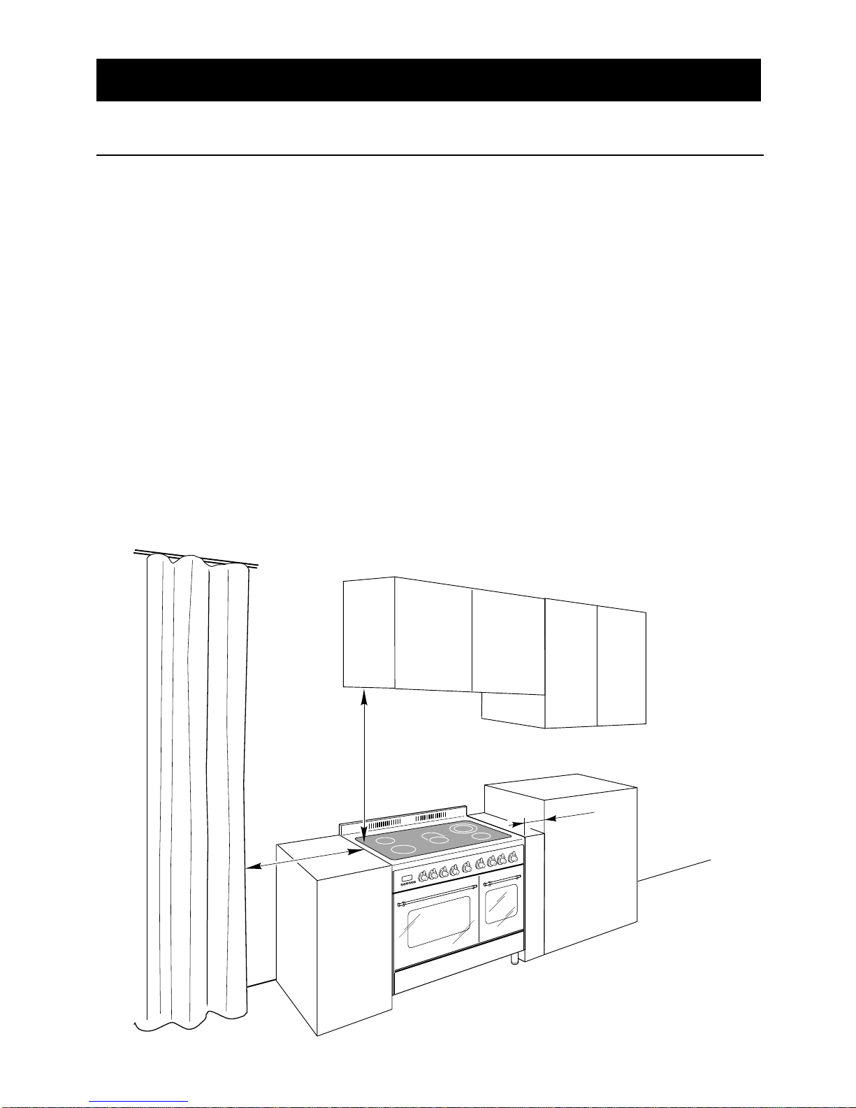
Space Requirements
Ensure that the specified ventilation
space around the appliance is not
obstructed.
Food Splashes
Always wipe clean the oven after use.
Food splashes can carry on cooking
next time and may become a fire haz-
ard.
Hot Surfaces
It is important to remember that the sur-
faces of cooking appliances get hot dur-
ing use and retain the heat for some
time after switching off.
It is therefore advisable to keep small
children away from the appliance.
The Grill and Top oven ele-
ment
are exposed, so take great care when
placing food in the oven or removing it.
Use the grill pan handles or gloves.
Safety Reminders