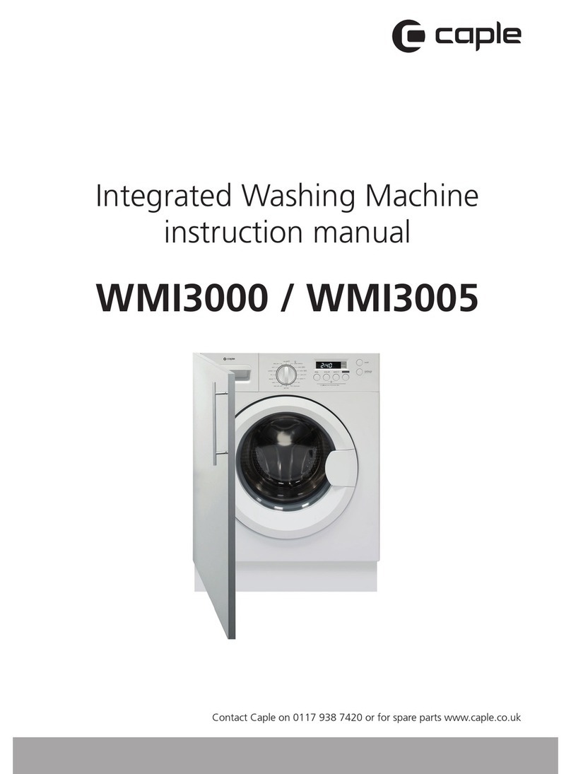
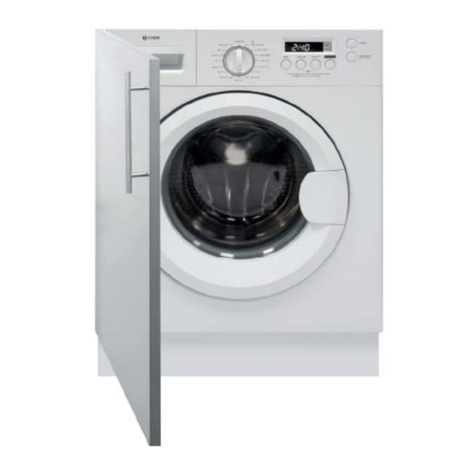
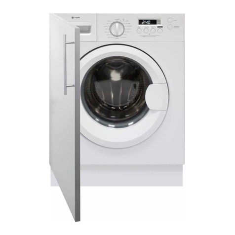
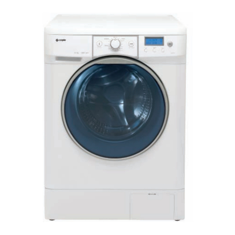
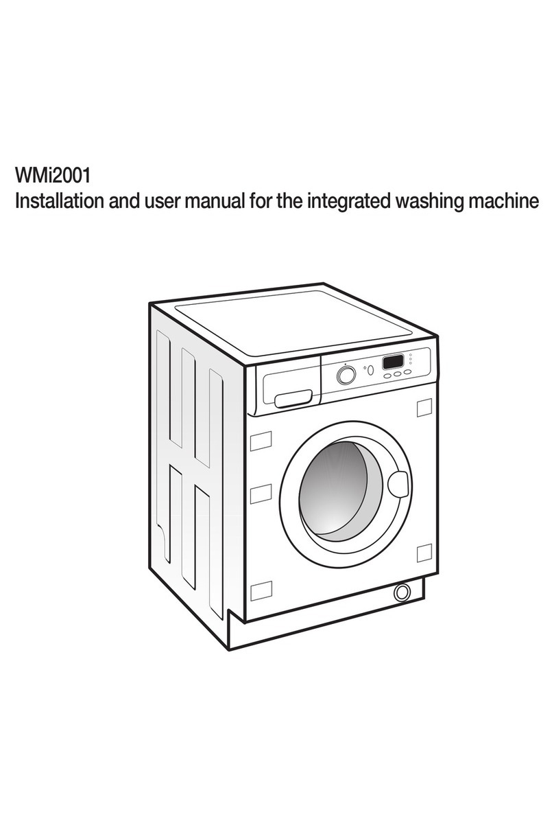
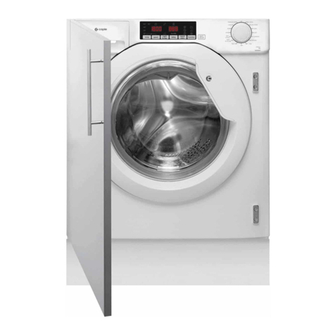
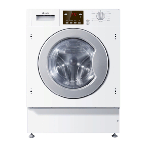
Caple WMI3001 User manual

Contact Caple on 0117 938 7420 for spare parts or www.caple.co.uk
Integrated Washing Machine
Instruction Manual
WMI3001 /
WMI3006

2Instruction manual WMi3001 & WMi3006 Please keep this instruction manual for future reference
CONTENTS
Warnings 3
Environmental Protection 9
Technical Fiche 9
Warranty 9
Product Overview 10
Installation 11
Built In Installation 15
Operation 20
Detergent Drawer 22
Quick User Guide 23
Control Panel 34
Programmes 30
Table Of Programmes 32
Cleaning And Maintenance 34
Troubleshooting 38
Product Specifications 41
Caple Contact Details 44

3Instruction manual WMi3001 & WMi3006Please keep this instruction manual for future reference
Keep these instructions for use with the appliance. If the
appliance should be sold or passed on to others, make
sure that the instructions are passed on with it. We
thank you for taking note of these suggestions before
installing and using the appliance. They have been
written for your personal safety and the safety of others.
CAUTION: HOT SURFACE
CAUTION: RISK OF FIRE
CAUTION: HOT SURFACE
CAUTION: RISK OF FIRE
WARNINGS
-If the supply cord is damaged, it must be replaced by
the manufacturer, its service agent or similarly qualified
persons in order to avoid a hazard.
-The new hose-sets supplied with the appliance are to
be used and old hose-sets should not be reused.
-This washing machine is for indoor use only.
-This appliance can be used by children aged from 8
years and above and persons with reduced physical,
sensory or mental capabilities or lack of experience
and knowledge if they have been given supervision or
instruction concerning use of the appliance in a safe
way and understand the hazards involved.
-Children shall not play with the appliance. Cleaning
and user maintenance shall not be made by children
without supervision.
-Children should be supervised to ensure that they do
not play with the appliance.

4Instruction manual WMi3001 & WMi3006 Please keep this instruction manual for future reference
-Children of less than 3 years should be kept away
unless continuously supervised.
-If the supply cord is damaged, it must be replaced
by a special cord or assembly available from the
manufacturer or its service agent.
-Only use the hose-sets supplied with the appliance
for the water supply connection (do not reuse old
hose-sets).
-Water pressure must be between 0.05 MPa and
1 MPa.
-Make sure carpets or rugs do not obstruct the base or
any of the ventilation openings.
-After installation, the appliance must be positioned so
that the plug is accessible.
-The maximum load capacity of dry clothes depends on
the model used (see control panel).
-To consult the product technical specification please
refer to the manufacturer website.
-This appliance is not intended for use by persons
(including children) with reduced physical, sensory
or mental capabilities, or lack of experience and
knowledge, unless they have been given supervision or
instruction concerning use of the appliance by a person
responsible for their safety.
-Pull out its plug from the power socket and turn off the
water tap before cleaning or maintenance.
-Make sure that all pockets are emptied.

5Instruction manual WMi3001 & WMi3006Please keep this instruction manual for future reference
-Sharp and rigid items such as coins, nails, screws or
stone etc may cause serious damages to this machine.
-Pull out its plug and cut off water supply after the
operation.
-Please check whether the water inside the drum has
been drained before opening its door. Please do not
open the door if there is any water visible.
-Animals and children may climb into the machine.
Check the machine before every operation.
-Take care that power voltage and frequency shall be
identical to those of washing machine.
-Do not use any socket with rated current less than that
of washing machine.
-Never pull out power plug with wet hands.
-Do not pull on the power cord or appliance to unplug
the machine.
-To ensure your safety, the power cord plug must be
inserted into an earthed three-pole socket. Check
carefully and make sure that your socket is properly
and reliably earthed.
-Packing materials may be dangerous to children.
Please keep all packing materials (plastic bags, foams
etc) far away.
-Washing machines shall not be installed in bathrooms
or wet rooms as well as in the rooms with explosive or
caustic gases.

6Instruction manual WMi3001 & WMi3006 Please keep this instruction manual for future reference
-The water and electrical connections must be
connected by a qualified engineer in accordance
with the manufacturer’s instructions and local safety
regulations.
-Before operating this machine, all packages and
transport bolts must be removed. Otherwise the
washing machine may be seriously damaged while
washing the clothes.
-This appliance is intended to be used in household and
similar applications such as:
› Staff kitchen areas in shops, offices and other
working environments.
› Farm Houses.
› By clients in hotels, motels and other residential type
environments.
› Bed and breakfast type environments.
-Before using the machine for the first time, the
washing machine shall be operated in one round of the
whole procedures without clothes inside.
-Before using the machine for the first time, the product
shall be calibrated.
-Your washing machine is only for home use and is only
designed for the textiles suitable for machine washing.
-Flammable and explosive or toxic solvents are
forbidden. Gasoline and alcohol etc shall not be
used as detergents. Please only select the detergents
suitable for machine washing.

7Instruction manual WMi3001 & WMi3006Please keep this instruction manual for future reference
-Do not wash carpets in this washing machine.
-Be careful of burning when washing machine drains
hot washing water.
-Never refill the water by hand during washing.
-Please remember to disconnect water and power
supply immediately after the clothes are washed.
-Do not climb up and sit on top cover of the machine.
-Do not lean against machine door.
-Please do not close the door with excessive force. If it
is found difficult to close the door, please check if the
excessive clothes are put in or distributed well.
-Transport bolts shall be reinstalled to the machine by a
competent person.
-The accumulated water shall be drained out of the
machine.
-Handle the machine carefully. Never hold any
protruded part on the machine while lifting. Machine
door cannot be used as the handle during the
conveyance. During transport, never rest the door on
the trolley. Two people are recommended to lift the
washing machine.
-Do not expose the washing machine to rain, direct
sunlight or other weather elements. Protect from
possible freezing.
-The use of converters, multiple sockets or extension
cords is strongly advised against.

8Instruction manual WMi3001 & WMi3006 Please keep this instruction manual for future reference
-In the event of fault and / or malfunction, turn off
the washing machine, close the water tap and do not
tamper with the appliance. Immediately contact Caple
service and only use original spare parts. Failure to
observe these instructions may jeopardise appliance
safety.
Explanation of the symbols:
This combination of symbol and signal word indicates a
potentially dangerous situation which may result in death or
serious injuries unless it’s avoided.
!WARNING
This combination of symbol and signal word indicates a
potentially dangerous situation which may result in slight or
minor injuries or damage to property and the environment.
CAUTION
WARNING: This combination of symbol and signal
word indicates a potentially dangerous situation which
may result in death or serious injuries unless it’s avoided.
Explanation of the symbols:
This combination of symbol and signal word indicates a
potentially dangerous situation which may result in death or
serious injuries unless it’s avoided.
!WARNING
This combination of symbol and signal word indicates a
potentially dangerous situation which may result in slight or
minor injuries or damage to property and the environment.
CAUTION
CAUTION: This combination of symbol and signal
word indicates a potentially dangerous situation which
may result in slight or minor injuries or damage to
property and the environment.

9Instruction manual WMi3001 & WMi3006Please keep this instruction manual for future reference
ENVIRONMENTAL PROTECTION
Waste electrical products should not be disposed of with household waste. Please recycle
where facilities exist. Check with your Local Authority or retailer for recycling advice. This
appliance is marked according to the European Directive on Waste Electrical and Electronic
Equipment (WEEE).
By ensuring this product is disposed of correctly, you will help prevent potential negative
consequences for the environment and human health, which could otherwise be caused
by inappropriate waste handling of this product. The symbol on the product indicates that
this product may not be treated as household waste. Instead it shall be handed over to the
applicable collection point for the recycling of electrical and electronic equipment. Disposal
must be carried out in accordance with local environmental regulations for waste disposal.
For more detailed information about treatment, recovery and recycling of this product, please
contact your local council, your household waste disposal service or the retailer where you
purchased the product.
CE DECLARATIONS OF CONFORMITY
This appliance has been manufactured to the strictest standards and complies with all
applicable legislation, Low Voltage Directive (LVD) and Electromagnetic Compatibility (EMC).
UKCA DECLARATIONS OF CONFORMITY
This appliance has been manufactured to the strictest standards and complies with all
applicable legislation.
TECHNICAL FICHE
This appliance conforms to all current and applicable energy regulations. To view the Technical
Fiche that supports the energy labelling data, please visit the product page on our website
www.caple.co.uk
WARRANTY
Your new appliance is covered by warranty. The warranty card is enclosed - if it is missing, you
must provide the following information to your retailer in order to receive a replacement: date
of purchase, model and serial number (placed on the inside of the appliance storage drawer).
Registration can also be completed online by visiting www.caple.co.uk.
Ensure you keep your warranty card safe, you may need to show it to Caple Service together
with proof of purchase.
If you fail to show your warranty card you will incur all repair charges.
Spare parts are only available from Caple Service and spare parts authorised centres.

10 Instruction manual WMi3001 & WMi3006 Please keep this instruction manual for future reference
Instruction manual WMi3000 / WMi3005
Please keep this instruction manual for future reference
9
OVERVIEW OF WASHING MACHINE
P.06 P.07
Safety Precautions Overview of Washing Machine
Inlet pipe
Transport
plughole
Component
Accessories
Door
Detergent Drawer Control Panel
Power Plug
Outlet Hose
Detergent Box
ENVIRONMENTAL PROTECTION
Waste electrical products should not be disposed of with household waste. Please
recycle where facilities exist. Check with your Local Authority or retailer for
recycling advice. This appliance is marked according to the European directive
2002/96/EC on Waste Electrical and Electronic Equipment (WEEE).
By ensuring this product is disposed of correctly, you will help prevent potential
negative consequences for the environment and human health, which could
otherwise be caused by inappropriate waste handling of this product. The symbol
on the product indicates that this product may not be treated as household waste.
Instead it shall be handed over to the applicable collection point for the recycling
of electrical and electronic equipment. Disposal must be carried out in accordance
with local environmental regulations for waste disposal.
For more detailed information about treatment, recovery and recycling of this
product, please contact your local council, your household waste disposal service
or the retailer where you purchased the product
CE DECLARATIONS OF CONFORMITYTI
This appliance has been manufactured to the strictest standards and complies
with all applicable legislation, Low Voltage Directive (LVD) and Electromagnetic
Compatibility (EMC).
Component
Accessories
Accessories
Transport
plughole
Supply hose hot
water (optional)
Supply hose
cold water
Drain hose
(optional
support
)
•The product line chart is for reference only, please refer to real product as
standard.
Note!
8
Owner’s manual
Product Description
INSTALLATION
Door
Detergent Drawer Control Panel
Power Plug
Drain hose
OVERVIEW OF WASHING MACHINE
COMPONENT
ACCESSORIES
Transport hole plug Supply hose
cold water
Drain hose support Owner’s manual
11Instruction manual WMi3001 & WMi3006Please keep this instruction manual for future reference
INSTALLATION
UNPACKING THE WASHER MACHINE
Unpack your washing machine and check if there is any damage during the transportation. Also
make sure that all the items (as shown on page 10) in the attached bag are received. If there is
any damage to the washing machine during the transportation, or any item is missing, please
contact your retailer immediately.
DISPOSE OF THE PACKING MATERIALS
!
WARNING
Keep packaging materials away from children.
The packing materials of this machine may be dangerous to children. Please dispose of them
properly. Please dispose of the related packing materials according to the relevant local
regulations. Please do no throw the packing materials away together with the other daily
living disposals.
REMOVE TRANSPORT BOLTS
!
WARNING
› You must remove the transport bolts from the backside
before using the product.
› You’ll need the transport bolts again if you move the
product, so make sure you keep them in a safe place.
Please take the following steps to remove the bolts:
1. Loosen all bolts with spanner and then remove along with the flat washers, rubber bungs
and plastic spacer tubes.
2. Cover the open transportation bolt holes with the plastic cap included in the instruction bag.
3. Keep the transport bolts, flat washers, rubber bungs and plastic spacer tubes stored away
safely for future use.
NOTE
During the removal of the bolts, spacer tubes fall inside the product. These can be removed
by tilting the product forward and recovering them from the floor or inside the base of
the machine.

12 Instruction manual WMi3001 & WMi3006 Please keep this instruction manual for future reference
1
2
3
SELECT THE LOCATION
!
WARNING
› Stability is important to prevent the product from moving.
› Make sure that the product does not stand on the power cord.
The washing machine must be placed in a location according to the below:
› Rigid, dry, and level surface (if not level, please make it level with reference to the following
figure “Adjust Legs”)
› Avoid direct sunlight
› Sufficient ventilation
› Room temperature is above 0°C
› Keep far away from heat resources.
› Do not install the washing machine on carpeted floor.
ADJUST LEGS
!
WARNING
The lock nuts on all four feet must be screwed tightly
against the housing.
Level the appliance using the feet:
1. Turn the nut clockwise to release the screw.
2. Rotate the foot to raise or lower it until it touches
to the floor.
3. Lock the foot, screwing in the nut, until it tightens against to the bottom of the
washing machine.
Check the washing machine is steady using a spirit level or by pressing the four corners on top
of the appliance in sequence.
NOTE: The 4 legs allow the height of the washing machine to be adjusted from 825mm to a
maximum of 835mm.

13Instruction manual WMi3001 & WMi3006Please keep this instruction manual for future reference
CONNECT INLET PIPE
!
WARNING
› To prevent leakage or water damage, follow the
instructions in this chapter.
› Do not kink, crush, modify or sever water inlet hose. The
washing machine should be installed in its final position
such that the inlet pipe is not trapped.
1. Connect the inlet pipe to the water supply tap. Only use
the pipe supplied with the appliance (do not reuse old
pipe-sets).
2. Connect the other end of the inlet pipe to the inlet valve
at the back of the washing machine and fasten the pipe
tightly clockwise.
NOTE:
If there is any leakage with the hose, repeat these steps to connect the inlet hose.
CONNECT OUTLET HOSE
!
WARNING
› Do not kink or trap the drain hose.
› Position drain hose properly, otherwise damage might result of water leakage.
› When installing drain hose, fix it properly.
› If drain hose is too long, do not force it into the washing machine as it will cause abnormal
noises.
The drain hose should be inserted into suitable drain pipe of between 60cm and 100cm height
above the floor using the curved drain hose support.
The drain hose can be connected in three different ways:
1. Connect it to a drain pipe
2. Attach it to a sink
3. Connect it to the sink drain pipe
15
93mm
Min.
Ø127mm
504mm
Please keep this instruction manual for future reference Instruction manual TDI4000 15
4
5
6
7
1
23
Mount the furniture door to the front
PLINTH VENTILATION
The plinth must have ventilation slots (min side/diameter 127mm hole) according to the
dimensions on the fixing template. If the plinth is not high enough to accommodate the entire
hole, cut only part of it.
»Place the template onto the reverse of the
plinth. Mark the screw hole positions, then
drill them out.
»Fix the plinth to the kick plate using 6
screws provided. (J)
NOTE:
This is only possible with some types of kick plate (e.g. wood or plastic). We suggest to check with
the kitchen suppliers.
J
Min. Ø127mm
105mm
93mm
93mm
Min.
Ø127mm
504mm
machine using the hinges. Fix the spacers (1) in
place with the 2 screws (2) and then fix the hinges
screws (3).
of the dryer using the hinges.
Fix the spacers (1) in place with the 2
screws (2) and then fix the hinges with 2
1
TDI4000 Instruction Manual Intergrated Tumble Dryer.indd 15TDI4000 Instruction Manual Intergrated Tumble Dryer.indd 15 07/04/2020 10:3007/04/2020 10:30
CONNEC T IN LET PIPE
1. Connect the inlet pipe to the water supply tap.
Only usethe pipe supplied with the appliance (do
not reuse old pipe-sets).
CONNECT OUTLET HOSE
The drain hose should be inserted into suitable drain pipe of between 60cm and 100cm height
above the floor using the curved drain hose support. Care must be taken to avoid kinking or
trapping the drain hose.
The drain hose can be connected in three different ways:
1. Connect it to a drain pipe
2. Attach it to a sink
3. Connect it to the sink drain pipe
NOTE:
The washer dryer should be installed in its final
position such that the inlet pipe is not kinked or
trapped. If there is any leakage with the hose,
repeat the steps to connect inlet hose.
2. Connect the other end of the inlet pipe to the
inlet valve at the back of the washing machine and
fasten the pipe tightly clockwise.
9
10
INSTALLATION
1.Check if the legs are closely attached to the cabinet. If not, please turn them to
their original positions tighten the nuts.
2.Loosen the lock nut turn the feet until it closely contacts with the floor.
3.Adjust the legs and lock them with a spanner, make sure the machine is steady.
Levelling the washer dryer
• The lock nuts on all four feet must be screwed tightly against the housing.
Connect Water Supply Hose
Connect the inlet pipe as indicated, There are two ways to connect the inlet pipe.
1.Connection between ordinary tap and inlet hose.
• To prevent leakage or water damage, follow the instructions in this chapter
Do not kink, crush, modify or sever .
!
•water inlet hose
• For the model equips hot valve,connect it to hot water tap with hot water supply
hose. Energy consumption will decrease automatically for some program.
234
1
Raise Lower
Lock nut
foot
Warning!
!
Warning!
!!
Loosen clamp nut and
four bolts
Tighten clamp nut Press slide bushing,
insert inlet hose into
connecting base
slide bushing
2341
Connection finished
clamp nut
Tap with threads and inlet hose Special tap for washer dryer
2.Connection between screw tap and inlet hose.
slide bushing
15
93mm
Min.
Ø127mm
504mm
Please keep this instruction manual for future reference Instruction manual TDI4000 15
4
5
6
7
1
23
Mount the furniture door to the front
PLINTH VENTILATION
The plinth must have ventilation slots (min side/diameter 127mm hole) according to the
dimensions on the fixing template. If the plinth is not high enough to accommodate the entire
hole, cut only part of it.
»Place the template onto the reverse of the
plinth. Mark the screw hole positions, then
drill them out.
»Fix the plinth to the kick plate using 6
screws provided. (J)
NOTE:
This is only possible with some types of kick plate (e.g. wood or plastic). We suggest to check with
the kitchen suppliers.
J
Min. Ø127mm
105mm
93mm
93mm
Min.
Ø127mm
504mm
machine using the hinges. Fix the spacers (1) in
place with the 2 screws (2) and then fix the hinges
screws (3).
of the dryer using the hinges.
Fix the spacers (1) in place with the 2
screws (2) and then fix the hinges with 2
1
TDI4000 Instruction Manual Intergrated Tumble Dryer.indd 15TDI4000 Instruction Manual Intergrated Tumble Dryer.indd 15 07/04/2020 10:3007/04/2020 10:30
CONNEC T IN LET PIPE
1. Connect the inlet pipe to the water supply tap.
Only usethe pipe supplied with the appliance (do
not reuse old pipe-sets).
CONNECT OUTLET HOSE
The drain hose should be inserted into suitable drain pipe of between 60cm and 100cm height
above the floor using the curved drain hose support. Care must be taken to avoid kinking or
trapping the drain hose.
The drain hose can be connected in three different ways:
1. Connect it to a drain pipe
2. Attach it to a sink
3. Connect it to the sink drain pipe
NOTE:
The washer dryer should be installed in its final
position such that the inlet pipe is not kinked or
trapped. If there is any leakage with the hose,
repeat the steps to connect inlet hose.
2. Connect the other end of the inlet pipe to the
inlet valve at the back of the washing machine and
fasten the pipe tightly clockwise.

14 Instruction manual WMi3001 & WMi3006 Please keep this instruction manual for future reference
1. Drain Hose connection to Drain Pipe
2. Drain Hose connection to Sink Drain Pipe
3. Drain Hose attached to Sink
4. Drain Hose Support
5. Water Inlet Pipe
6. Electrical Connection
NOTE
When using the outlet hose support, please install it like the above image. If the outlet hose is
too long, do not force it into the washing machine as it will cause abnormal noises.
When installing outlet hose, fit it properly with rope.
WARNING
Contact Caple Service should the power cord need replacement. Installation faults are not
covered by the manufacturers warranty.
DIMENSIONS
1
2
3
4
5
6

15Instruction manual WMi3001 & WMi3006Please keep this instruction manual for future reference
BUILT IN INSTALLATION
Before installing the washing machine, please read these built-in instructions carefully and keep
for future reference. This appliance has been designed to be built into the kitchen furniture. The
recess should have the dimensions as shown in the figure below:
WARNING
When installing the appliance into the kitchen, if possible, ensure the hoses are placed in either
of the two recesses on the back of the appliance. This will help to prevent the hoses from being
kinked or trapped.
DIMENSIONS
540mm
152.5mm
min. 825mm
600mm
595mm
560mm
825-835mm

16 Instruction manual WMi3001 & WMi3006 Please keep this instruction manual for future reference
Door opening from left to right
PREPARATION AND ASSEMBLY OF THE DOOR
The appliance is prearranged for the assembly of a door opening from right to left or from left
to right.
APPENDIX
1. Self-tapping screws (ST4*12)
2. Self-tapping screws (M5*12)
3. Hinges
4. Counter magnet
5. Spacer
6. Door template
TOOLS
1. Screw Driver
2. Automatic Driver
3. Ruler
4. Pencil
Appendix
Self-tapping
screws(ST4*12)
Self-tapping
screws
(M5*12)
Hinges
Counter magnet Spacer Fixed position
paper
Tool
Screw driver Automatic driver Ruler Pencil
Built-in installation
Install Steps
Overview
1
825mm
600mm
540mm
595mm
152.5mm
580mm
825mm
Preparation and assembly of the door
The door is open from right to leftThe door is open from left to right
10
28
MAINTENANCE
Appendix
Self-tapping
screws(ST4*12)
Self-tapping
screws(M5*12)
Hinges
Counter magnet Spacer Fixed position
paper
Tool
Screw driver Automatic driver Ruler Pencil
Built-in installation
Install Steps
Overview
1
825mm
600mm
540mm
595mm
152.5mm
580mm
825mm
Preparation and assembly of the door
The door is open from right to leftThe door is open from left to right
10
28
MAINTENANCE
Appendix
Self-tapping
screws(ST4*12)
Self-tapping
screws
(M5*12)
Hinges
Counter magnet Spacer Fixed position
paper
Tool
Screw driver Automatic driver Ruler Pencil
Built-in installation
Install Steps
Overview
1
825mm
600mm
540mm
595mm
152.5mm
580mm
825mm
Preparation and assembly of the door
The door is open from right to leftThe door is open from left to right
10
28
MAINTENANCE
Appendix
Self-tapping
screws(ST4*12)
Self-tapping
screws
(M5*12)
Hinges
Counter magnet Spacer Fixed position
paper
Tool
Screw driver Automatic driver Ruler Pencil
Built-in installation
Install Steps
Overview
1
825mm
600mm
540mm
595mm
152.5mm
580mm
825mm
Preparation and assembly of the door
The door is open from right to leftThe door is open from left to right
10
28
MAINTENANCE
Door opening from right to left
1.
1. 2. 3. 4.
3.
5.
2.
4.
6.

17Instruction manual WMi3001 & WMi3006Please keep this instruction manual for future reference
DOOR TEMPLATE PREPARATION
1. Make the mark on the door according to the cupboard and washing machine height.
2. Fix door template onto the door.
Position Paper
Make the mark on the door
1
Position Paper Position Paper
Fixed position paper on the door.
2
16-22mm
12mm
35mm
12mm
2mm
Drill hole on the door
3
10
29
Top To p
Left Open Right Open
MAINTENANCE
Position Paper
Make the mark on the door
1
Position Paper Position Paper
Fixed position paper on the door.
2
16-22mm
12mm
35mm
12mm
2mm
Drill hole on the door
3
10
29
Top Top
Left Open Right Open
MAINTENANCE
Cut door template paper Paste on the door
(the door on the right)
Paste on the door
(the door on the left)

18 Instruction manual WMi3001 & WMi3006 Please keep this instruction manual for future reference
DRILL HOLES ON THE DOOR
1. Drill the holes on the door according to the
door template.
2. Installing the hinges and spacer.
Fix the hinges to the furniture door with
the ST4*12 screws. The hinges can be
adjusted to compensate for possible uneven
thickness of the door.
INSTALLING THE DOOR MAGNET
The appliance is designed with magnetic closure of the door. To enable correct operation of this
device, it is necessary to screw the counter-magnet into the inner side of the door.
Position Paper
Make the mark on the door
1
Position Paper Position Paper
Fixed position paper on the door.
2
16-22mm
12mm
35mm
12mm
2mm
Drill hole on the door
3
10
29
Top To p
Left Open Right Open
MAINTENANCE
Installation the hinges and spacer
Installation the counter magnet
5
Installation the door
6
44
•
When installing the appliance into the kitchen ensure furniture ,if possible, the hoses are
placed in either of the two recesses on the back of the appliance. This will help to prevent
the hoses from becoming kinked or trapped.
Warning!
!
10
30
MAINTENANCE

19Instruction manual WMi3001 & WMi3006Please keep this instruction manual for future reference
INSTALLING THE DOOR
NOTE
The furniture door should not exceed 9kg

20 Instruction manual WMi3001 & WMi3006 Please keep this instruction manual for future reference
OPERATION
BEFORE WASHING
EMPTY ALL POCKETS
Foreign objects (e.g. nails, coins, paper, clips, etc.) can cause damage to garments and to the
components in the machine.
Check the laundry before washing and remove foreign objects.
SORT THE LAUNDRY
Sort the laundry by colour and care label. Most garments have a textile care label in the collar
or side seam.
TIP: Dark textiles often contain excess dye and should be washed separately several times
before being included in a mixed load. Always wash whites and colours separately.
PRE-TREAT STAINS
Badly soiled areas, stains etc. should be cleaned as soon as possible, preferably whilst still
fresh. Spillages should be carefully dabbed off using a soft, colour fast cloth. Do not rub.
TIP: Badly soiled areas can be pretreated with a liquid detergent, stain removers etc. first,
following the manufacturer’s instructions. With particularly stubborn stains ask your dry
cleaner for advice.
Solvent-based cleaners (e.g. benzine) can damage plastic parts. When pre-treating
garments, make sure that any plastic parts (e.g. buttons) are protected from
cleaning agent.
Chemical (solvent-based) cleaning agents can cause severe damage to the washing
machine. Do not use solvent-based cleaning agents in the machine.
GENERAL TIPS:
Curtains: Remove lead weights first or place in a laundry bag.
Underwiring and collar stiffeners: Any loose wiring in bras, shirt collar stiffeners, etc. should be
removed or sewn in.
Other manuals for WMI3001
1
This manual suits for next models
1
Table of contents
Other Caple Washer manuals

Caple
Caple WMF1020 User manual

Caple
Caple WMI4000 User manual

Caple
Caple WMI4001 User manual

Caple
Caple WMI3000 User manual

Caple
Caple WMI3001 User manual

Caple
Caple WMI3005 User manual

Caple
Caple WMi2001 User manual

Caple
Caple WMF1020 User manual

Caple
Caple WMi2003 User manual

Caple
Caple WMI1010 User manual