Capsa Healthcare M40 User manual

User Manual
M40 Computer Carts
Elevating performance, every day.

2
Warnings
IMPORTANT – Indicates a situation that does not present any hazard but is
very important in maintaining a well functioning workstation.
ATTENTION – Consult manual to avoid a potentially hazardous situation which
may result in minor or moderate injury.
ELECTRICAL – Indicates an impending electrical hazard
which, if not avoided, may result in personal injury, re and/or death.
• The supplied power cord is rated for medical use. Connecting the cord to an outlet
that is not medical grade (indicated with a green dot) will not ensure grounding
protection.
• Where the integrity of the external protective earth ground conductor arrangement
is in doubt, the equipment shall be operated from its internal electrical power source
(battery).
• Power cord, USB extension, and workstation are for indoor use only. DO NOT
operate outdoors.
• Keep power cord away from water. DO NOT plug cord into outlet if wet.
• DO NOT operate product if wet. If the work station becomes wet, unplug it
immediately, wipe off any excess liquid, and allow it to dry before using again.
• Inspect power cord before integration. DO NOT use power cord if damaged.
• Fully insert power cord plug into outlet. DO NOT unplug by pulling on cord.DO
NOT remove, bend or modify any metal prongs or pins of power cord.
• DO NOT use excessive force to make mechanical or electrical connections.
• DO NOT obstruct the cooling vents.
• DO NOT use an electrical extension cord with your workstation.
• DO NOT use a ammable cleaner on the station as it can result in re or explosion.
• DO NOT overload the cart. Weight of all customer installed technology not to exceed
30 lbs. (13.6 kg). Weight of monitor not to exceed 15 lbs. (6.8 kg).
• DO NOT operate the cart on an incline exceeding 10 degrees.
• DO NOT use the cart to power equipment that is not part of the congured cart
system.
• DO NOT connect equipment that is not mounted on the cart into the power system
outlets. The power system is designed for power cart mounted equipment only.
• Equipment not suitable for use in the presence of a ammable anesthetic xture with
with metered oxygen or nitrous oxide.
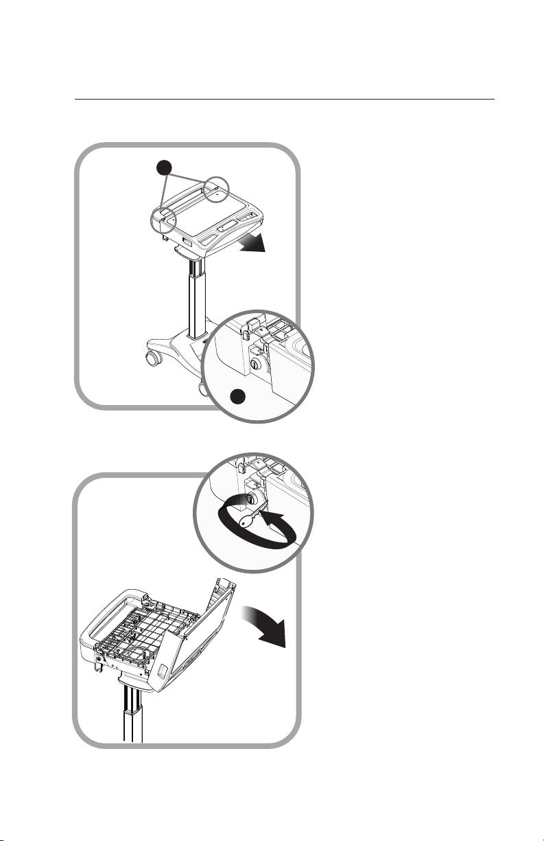
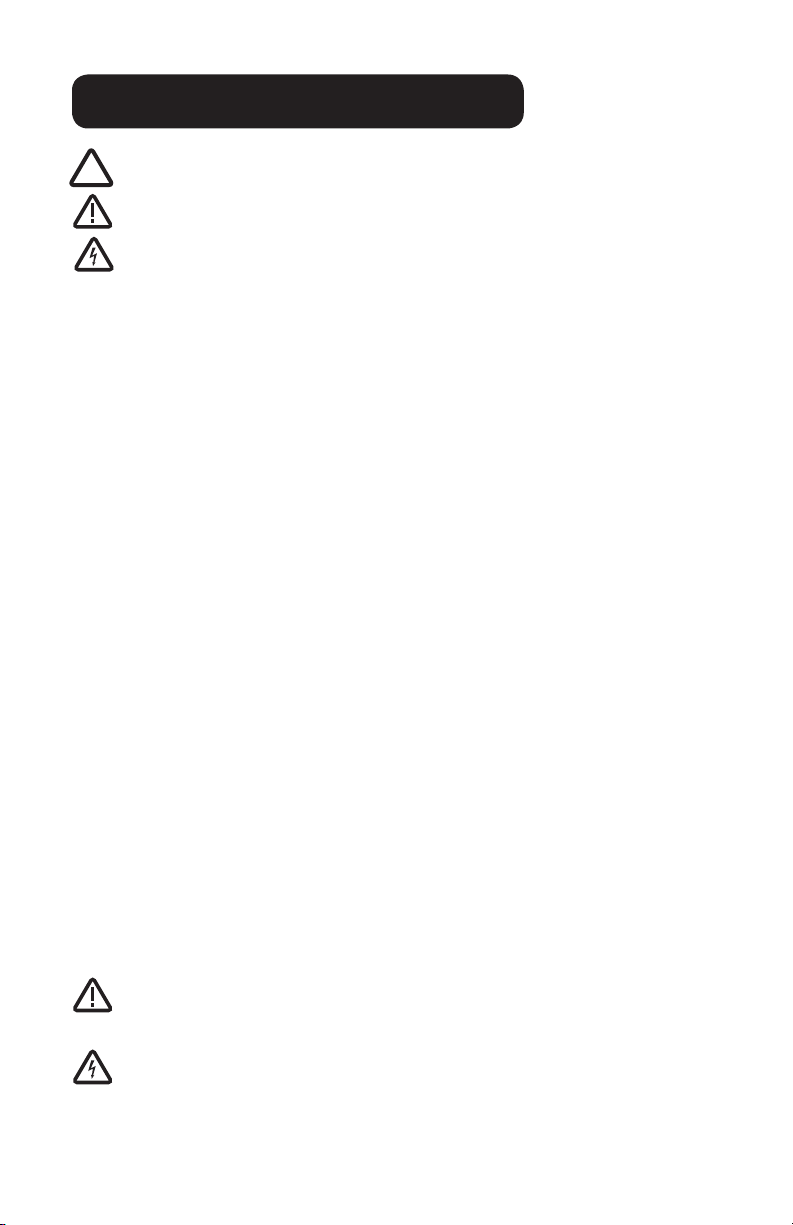
Do not adjust lift mechanism until cart has been outtted with technology.
Failure to do so may cause the shuttle and work surface to rise rapidly when
actuator is released potentially causing personal injury or damage to the cart.
To avoid potential electrical shock, DO NOT simultaneously touch any cart
system components and the patient or any apparatus not connected to the cart
system. Electric current may try to ow through you between the system and the
other point of contact as it seeks the easiest path to ground.

3
Table of Contents
Warnings 2
Introduction 4
Box Contents ...................................................................5
Specications ...................................................................6
Overall View......................................................................7
Get Started 8
Install the Power Cord ......................................................8
Install the Monitor Support................................................8
Setup 9
Open the Work Surface ...................................................9
Install the Keyboard Mouse and Data Cable ....................10
Install the laptop Power supply .........................................11
Install the Laptop .............................................................12
Install the Monitor ............................................................13
Install the CPU..................................................................13
Operation 15
Operating Procedure ........................................................15
Casters.............................................................................15
Height Adjustment............................................................16
Task Light.........................................................................16
Laptop/Storage Tray.........................................................17
Tech Box ..........................................................................18
Maintenance 18
Preventive Maintenance 19
Inspection Checklist .........................................................19
Troubleshooting 20
Service 20
Service Request ...............................................................20
Service Level Commitment ...............................................20
Cleaning 21
Recommendations ...........................................................21
Cleaning of High Touch Point Items ..................................21

4
Transport/Storage/Disposal 22
Transport/Storage.............................................................22
Cart Disposal....................................................................22
Standards Compliance 22
Test Compliance...............................................................22
Product Classication .......................................................22
Warranty 23
Limited Warranty for M40 Computer carts ........................23
Service Details..................................................................23

5
Introduction
BOX CONTENTS
C
A
x2
B
Taped to mouse holder
x2
B
Taped to mouse holder
A
C
D
x2 B
Taped to mouse holder
A
6 x M6 x 10 Machine Screws
EF
A
D
C
B
M40 Cart
Security Keys
Power Cord
Monitor Support
EMounting Screws
FM40 User Manual
GAccessory Kit
G1
G3
G2
Power Cord Clip
Mouse/Keyboard Cord Clips
Security Bit Kit
G4 Drawer Module Lock Overide Key †
† Carts Equipped with Drawer
Modules Only
G3
G2
G1 G4
G
D
Laptop Cart
Laptop Cart with Power Cord Kit
LCD & CPU Cart

6
SPECIFICATIONS
Base Size 17” x 19” (43 cm x 48 cm)
Weight Congurations starting at 53 lb (28.6 kg)
Height Adjustment 16” (40.5 cm)
Laptop/Storage Tray 16“ x 12“ x 1.5"
Accomodates up to 17” laptop or tablet computer
Work Surface 20” W x 11” D (50.8 cm W x 27.9 cm D)
Keyboard Platform Accommodates 1.75” H x 18" W x 8” D
(4.5 cm x 45.7 cm x 20.3 cm) USB keyboard
Mouse Area Bi-directional mouse pad 8.5" x 9.5” (21.5 cm x 24.1 cm)
USB Powered Task Light USB A to Mini-B
Document cover 19.5” x 9.75” (99.5 cm x 24.75 cm)
Power Supply Compartment 20“ x 5.75“ x 1.75”
Power Cord 2.5 ft (.75 m ) hospital grade spiral cord – extends to 8
ft (2.4 m), recharges on board technologyg, 120/240
Vac, 6.3A, 50/60 Hz
Power Strip 3 - NEMA 5/15 outlets with inline fusing
Laptop Cart with Power Cord Kit
LCD & CPU Cart
Tech Box 14.5” x 9.4" x 2.7" (36.8 cm x 23.8 cm x 6.9 cm)
LCD Monitor Mount 15 lbs (6.8) kg) max.
Power Cord 2.5 ft (.75 m ) hospital grade spiral cord – extends to 8
ft (2.4 m), recharges on board technologyg, 120/240
Vac, 6.3A, 50/60 Hz
Power Strip 3 - NEMA 5/15 outlets with inline fusing
Common Specications
STATEMENT OF USE
Introduction Introduction
The M40 Mobile Computing Cart is designed and manufactured by Capsa Healthcare.
Capsa Healthcare’s goal is to elevate your performance by offering innovative solutions
that positively impact clinical effectiveness and enhance medication management
processes throughout all healthcare environments.
• The M40 Mobile Computer Cart is a mobile computing workstation cart designed for
safe use in general patient areas for the purpose of clinical data entry and retrieval as
well as medication delivery
• The M40 Mobile Computer Cart is not intended for home use
• The M40 Mobile Computer Cart has no potential electromagnetic or other interference
risks when operated according to guidelines covered in this instruction manual

7
SPECIFICATIONS
STATEMENT OF USE
Laptop
Power Supply
Enclosure
Work Surface
Keyboard
Drawer
Mouse Holder
Plug Holder
Laptop
Monitor
Cable Clamp
Tech Box
Mousing
Surface
Keyboard
Drawer
Keyboard
Document Cover
Mouse Holder
Mouse
Task Light
Mouse
Security Door
Power Strip
CPU
Monitor Support
Monitor
Introduction
OVERALL VIEW
Introduction
Laptop Cart
LCD & CPU Cart

8
1
2
2
2
3
1
Get Started
INSTALL THE POWER CORD
INSTALL THE MONITOR SUPPORT
1. Plug the power cord into the
computer cart.
2. Position the bale to secure
the power cord.
3. Stow the plug in the holder.
1. Install the monitor support
with four screws as shown.
Do not tighten.
2. Install 2 screws as shown.
Tighten all 6 screws.

9
1
2
2
2
1
1
2
Get Started Setup
INSTALL THE POWER CORD
1. Unlock the work surface as
shown.
2. Lift the rear of the work
surface to expose the
storage/laptop tray.
1. Press the two latches to
release the work surface.
2. Pull the work surface forward
to expose the locks.
OPEN THE WORK SURFACE

10
1
2
1
2
1
2
1
2
Setup
INSTALL THE KEYBOARD MOUSE AND DATA CABLE
1. Route the keyboard cable to
the tech box/laptop tray.
2. Route the mouse cable to
the tech box/laptop tray.
3. If you are using a wired
network, route a data cable
to the tech box/laptop tray.
Note: Use cable ties to secure
the cables to the cart for strain
relief.
1. Open the keyboard drawer.
2. Place the keyboard in the
keyboard drawer.
3. Place the mouse in the
mouse holder.

11
1
2
1
2
3
Setup
INSTALL THE LAPTOP POWER SUPPLY
Setup
1. Place the power supply in the
power supply tray.
2. Fasten the power supply to
the tray with cable ties.
3. Route the computer power
cable to the laptop tray.
Stow the plug as shown.
1. Place the power supply in the
power supply enclosure.
2. Route the computer power
cable to the laptop tray.
3. Plug the power supply into
the power strip.
Laptop Cart With the
Power Cord Kit
Laptop Cart Without
the Power Cord Kit
Note: Use cable ties to secure
the power cord to the tray for
strain relief.

12
1
3
2
1
2
Setup
INSTALL THE LAPTOP
1. Place the laptop computer in
the laptop tray.
2. Make the necessary cable
and electrical connections.
Note: The task light must be
plugged into a powered USB
port or it will not work. (See
your computer documentation
for the location of the powered
USB ports.)
1. Position the laptop as
shown.
2. Lower the work surface.
3. Lock and close the work
surface.

13
1
1
2
INSTALL THE MONITOR
Setup Setup
INSTALL THE CPU
Cart with LCD & CPU Mounts
1. Mount the monitor to the
cart.
2. Route the monitor power to
the tech box.
1. Press the two latches to
release the tech box door.
2. Lower the door.
Note: Use the mounting screws
supplied with the monitor.
Note: Ensure full movement
of the monitor mount! To
avoid damage to the monitor
connections, verify there is
enough cable slack to allow
for full rotation of the mount
and that accessories do not
interfere with the range of
motion.

14
2
1
2
2
3
INSTALL THE CPU
Setup
1. Place the CPU in the tech
box.
2. Make the necessary electrical
and cable connections.
3. Close and lock the security
door.
4. Close the tech box door.
5. Lock and close the work
surface.
Note: Install CPU with the
power button accessible from
the top.
Note: The task light must be
plugged into a powered USB
port or it will not work. (See
your computer documentation
for the location of the powered
USB ports.)
1. Insert the key where shown
2. Rotate it clockwise/
counterclockwise to unlock
the security door.
3. Open the security door by
pulling it outward.

15
5
3
6
1
2
4
1
2
Operation
OPERATING PROCEDURE
Setup
CASTERS
1. Move the Cart into position.
2. Lock the casters.
3. Adjust the height of the work
surface.
4. Plug in the power cord. Plug
in the network cable if you
are using a wired network.
5. Start the computer.
6. Extend the keyboard drawer
and the mousing surface.
To operate braking casters:
1. Lower the tab with your toe to
lock a caster.
2. Lift the tab with your toe to
unlock a caster.
To operate tracking casters:
1. Lower the tab with your toe to
engage tracking feature.
Note: When the tab is lowered,
the tracking caster will align to
the nearest angle position.
2. Lift the tab with your toe to
disengage the tracking feature.

16
1
2
2
HEIGHT ADJUSTMENT
Operation
TASK LIGHT
1. Hold the work surface steady
and lift up and hold the
height adjustment handle.
2. Raise or lower the work
surface, then release the
handle.
1. Press the button to turn
the task light on.
2. Press the button again to turn
the task light off.
3. The task light will automatically
turn off after 3 minutes.
Note: The task light must be
plugged into a powered USB
port or it will not work. (See your
computer documentation for the
location of the powered USB ports.)

17
2
1
1
2
2
1
LAPTOP/STORAGE TRAY
OperationOperation
1. Unlock the work surface
locks as shown.
2. Lift the rear of the work
surface to expose the
Storage/Laptop Tray.
1. Press the two latches to
release the work surface.
2. Pull the work surface
forward to expose the laptop
computer power switch and
work surface locks.
Note: If The laptop power
switch is inaccessible, you will
have to unlock and open the
work surface.

18
1
2
Maintenance
DO NOT use the computer cart if pieces are missing or the unit is damaged. In
these cases, immedieately contact Capsa Healthcare Customer Service for more
information at: 1.800.437.6633.
Cables: Always keep the cables neatly organized and be sure to route the cables
away from moving components with wire ties or cable clips.
Electric Cables: Periodically inspect the power cord and the plug to ensure the
plug is not bent and the cable is not frayed.
Operation
TECH BOX
1. Press the two latches to
release the tech box door.
2. Lower the door.
Raise the door until it is latched
on both sides.
Open the Tech Box
Close the Tech Box

19
INSPECTION CHECKLIST
Preventative Maintenance
Items Action Benet
Power supply Check voltage and current
output to original power
supply specications. Inspect
fan and airow for dust and
lint buildup.
Helps prevent unexpected
power failures and ensures
proper airow to power system
for cooling.
AC power
cord and
internal cables
assemblies
Inspect wires and
components for any damage;
ensure there are no loose
connectors.
Identies potential safety issues,
extends life of battery, ensures
consistent recharging and
optimizes workstation runtime.
Casters Check casters for proper
tightness, ensure casters are
free of dirt and grime and
operate smoothly.
Mitigates risk of injury due to
loose casters. Ensures proper
maneuverability of workstation.
Inspect base
covers and
hardware
Check for loose or broken
covers.
Ensures proper airow and
power system cooling. Prevents
unexpected power failure;
mitigates chance for interrupted
workow and clinical processes.
Inspect
keyboard tray
movement
Check range of keyboard
tray for full eld of motion and
stability.
Proper adjustment supports
ergonomic capability that meets
unique requirements of multiple
users.
Inspect work
surface area
Inspect work surface for
cleanness and damage.
Promotes proper infection
control practices and maintains
protected area for internal
electrical components.
Inspect height
adjustment
Check height adjustment for
proper function, including full
range of motion.
Facilitates simple height and
ergonomic adjustments;
ensures comfortable use by
clinical staff.
Inspect
keyboard light
Check all lighting and switch
operation; conrm lights
function properly.
Supports proper lighting for
reading, work surface tasks,
and safe cart maneuvering in
low light environments.
Inspect all bins
and drawers
Check functionality of bins
and drawers including locking
function.
Smooth operation of bins
and drawers provides secure,
organized storage.
Inspect mounted
accessories
Check for secure t to mount
area and tighten if necessary.
Ensure stable accommodation
of peripheral device holders and
other accessories and supplies.
To protect optimal performance, Capsa Healthcare recommends a periodic inspection and
preventative maintenance of your computing cart eet. These simple steps can safeguard
against breakdowns and help you realize uninterrupted workow and cart availability.
Operation

Troubleshooting
Service
SERVICE REQUEST
Please visit our website at: www.capsahealthcare.com/request-service to le a request for
parts.
SERVICE LEVEL COMMITMENT
Capsa Healthcare is committed to providing best-in-class service. This document details
our standard warranty and instructions on how to request service using our customer
support system.
Problem Solution
Cart Will Not Raise or
Lower
Check for cable obstructions (kinks).
Cart is Hard to Push Verify the caster locks are in the unlocked (up) position.
Examine casters for any debris caught in or under the casters.
Keyboard Tray Does
Not Raise or Lower
Inspect for cable obstructions.
Adjust the keyboard arm tray knob counterclockwise to
loosen.
Adjust the keyboard arm tray knob clockwise to tighten.
Task Light Does Not
Work
Make sure USB cable is plugged into a powered USB port.
Computer/Monitor will
not power up.
Check that cart is plugged in.
Check that device power cables are connected.
Check that wall outlet has power.
Check fuses at cart power inlet.
Keyboard Does Not
Work Properly
Ensure the USB hub is powered and plugged into the power
supply (green light indicator).
Make sure the keyboard is plugged into the USB hub.
If the problem persists, plug the device into another car to see
if it functions properly.
Computer Does Not
Work Properly
Verify the computer has power.
If the problem persists, plug the device into another cart to
verify it is functioning properly.
20
Table of contents