Captron CHT5 User manual

CHT5 / CHT51
Original Operating Instructions
CHT5-2 / CHT51-2
CHT5 / CHT51
Original Operating Instructions
CHT5-2 / CHT51-2
2/15 1.2 CHT5 / CHT51
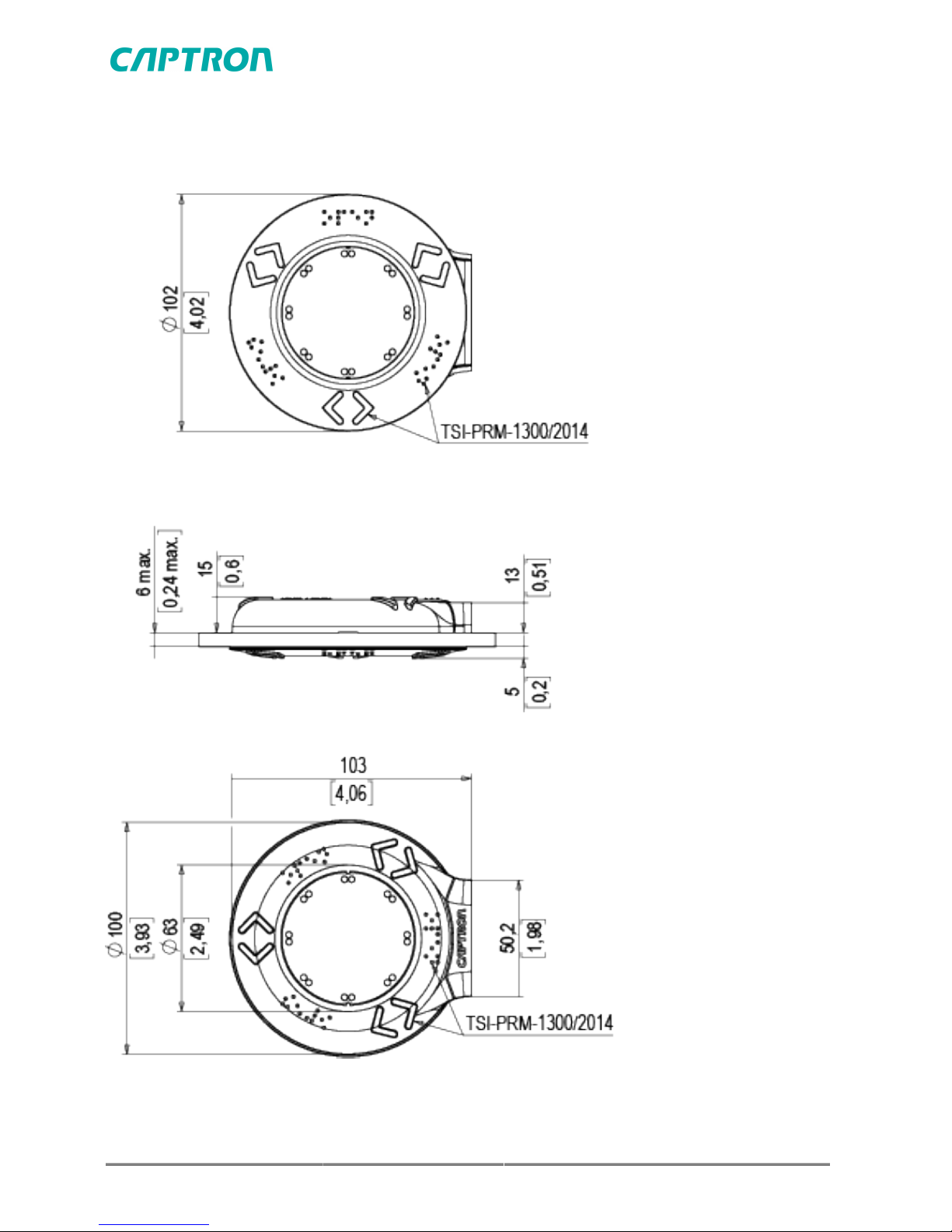
1 Dimensional drawing
CHT5

CHT5 / CHT51 1.2 3/15
CHT51

4/15 1.2 CHT5 / CHT51
2 Technical specifications
CHT5 and CHT51 PNP-NO, 4-pin 24 V
Operating voltage DC 24 V (16.8 …32 V)
Load current Max. 200 mA
Output pulse ~ 1 s (depending on the actuation duration)
Reverse polarity protection Protection of all lines
Short circuit protection Protected against short circuit and overload
Voltage drop Max. 3 V at 400 mA
Power consumption at 24 V Max. 30 mA
Operating temperature -30°C (-22°F)….+80°C (176°F)
Degree of protection IP Front IP69K
Type of actuation Capacitive
Actuation force No actuation force required
CHT5 and CHT51 PNP-NO, 5-pin 24 V
Operating voltage DC 24 V (16.8 …32 V)
Load current Max. 200 mA
Output pulse ~ 1 s (depending on the actuation duration)
Reverse polarity protection Protection of all lines
Short circuit protection Protected against short circuit and overload
Voltage drop Max. 3 V at 200 mA
Power consumption at 24 V Max. 35 mA
Operating temperature -30°C (-22°F)….+70°C (158°F)
Degree of protection IP Front IP69K
Type of actuation Capacitive
Actuation force No actuation force required
CHT5 / CHT51 1.2 5/15
CHT5 PNP-NO, 4-pin 110 V
Operating voltage DC 110 V (77 …137.5 V)
Load current Max. 15 mA
Output pulse ~ 1 s (depending on the actuation duration)
Reverse polarity protection Protection of all lines
Short circuit protection Protected against short circuit and overload
Voltage drop Max. 3 V at 10 mA
Power consumption at 110 V Max. 15 mA
Operating temperature -25°C (-13°F)….+70°C (158°F)
Degree of protection IP Front IP69K
Type of actuation Capacitive
Actuation force No actuation force required
CHT5 PNP-NO, 4-pin 12 V
Operating voltage DC 12 V (8.4 …15.6 V)
Load current Max. 200 mA
Output pulse ~ 1 s (depending on the actuation duration)
Reverse polarity protection Protection of all lines
Short circuit protection Protected against short circuit and overload
Voltage drop Max. 3 V at 200 mA
Power consumption at 12 V Max. 20 mA
Operating temperature -30°C (-22°F)….+70°C (158°F)
Degree of protection IP Front IP69K
Type of actuation Capacitive
Actuation force No actuation force required
6/15 1.2 CHT5 / CHT51
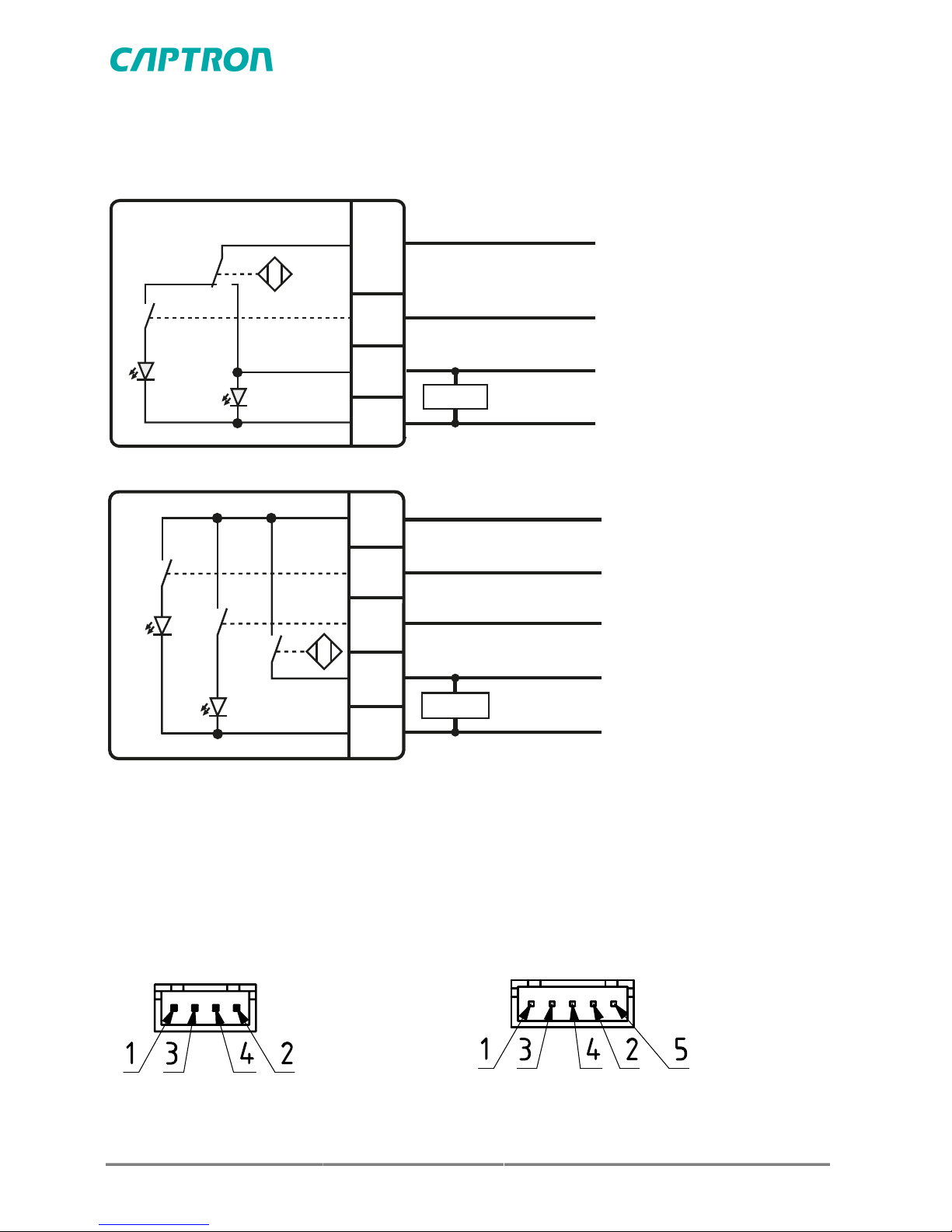
3 Connection plan
PNP-NO, 4-pin
+VDC
+VDC / LED1
PNP-NO
0V
3
4
2
1
LED1
LED2
brown
white
black
blue
Load
PNP-NO, 5-pin
LED1
LED2
+VDC / LED1
+VDC / LED2
PNP-NO
0V
+VDC
3
4
2
5
1
brown
white
grey
black
blue
Load
4 Connection options
Connector
CHT5-26#…. CHT51-26#….
Connector JST 2.54, 4-pin
CHT5-2M#…. CHT51-2M#….
Connector JST 2.0, 5-pin

CHT5 / CHT51 1.2 7/15
Cable
CHT5-20#….
Cable, 4-pin
2 m cable with wire end ferrules
Wire end ferrules with plastic collars DIN 46228
Wire cross-section strands 0.25 mm2
Foreword
This manual has been written for technicians/installers and operators and
should be kept for future reference. Read these operating instructions carefully
and make sure that you have fully understood the contents before installing or
working with the CHT5 or CHT51.
5 Safety
WARNING
Improper work on electrical systems!
Electric shock can result in death or life-threatening injuries.
4Before working on electrical systems, disconnect them from their
voltage supply and secure them against being switched on again.
4Work on electrical installations should only be carried out by qualified
personnel.
4Wear appropriate personal protective equipment (PPE).
5.1 Intended use
The SENSORswitch is designed for use in accordance with the technical
specifications. The values can be found in the “Technical specifications” chapter
and the “Product description”.
5.2 Reasonably foreseeable misuse
A use other than that specified under chapter Intended use or extending
beyond this is deemed to be improper.

8/15 1.2 CHT5 / CHT51
The SENSORswitch is not suitable for:
■use in potentially explosive atmospheres.
■use as a safety component as per directive 2006/42/EC
6 General description
The supplied SENSORswitch can have options that differ from those shown in
this manual. This does not affect the function. The SENSORswitch is equipped
with different color LEDs to indicate operating conditions. The LEDs are
actuated differently depending on the pin configuration.
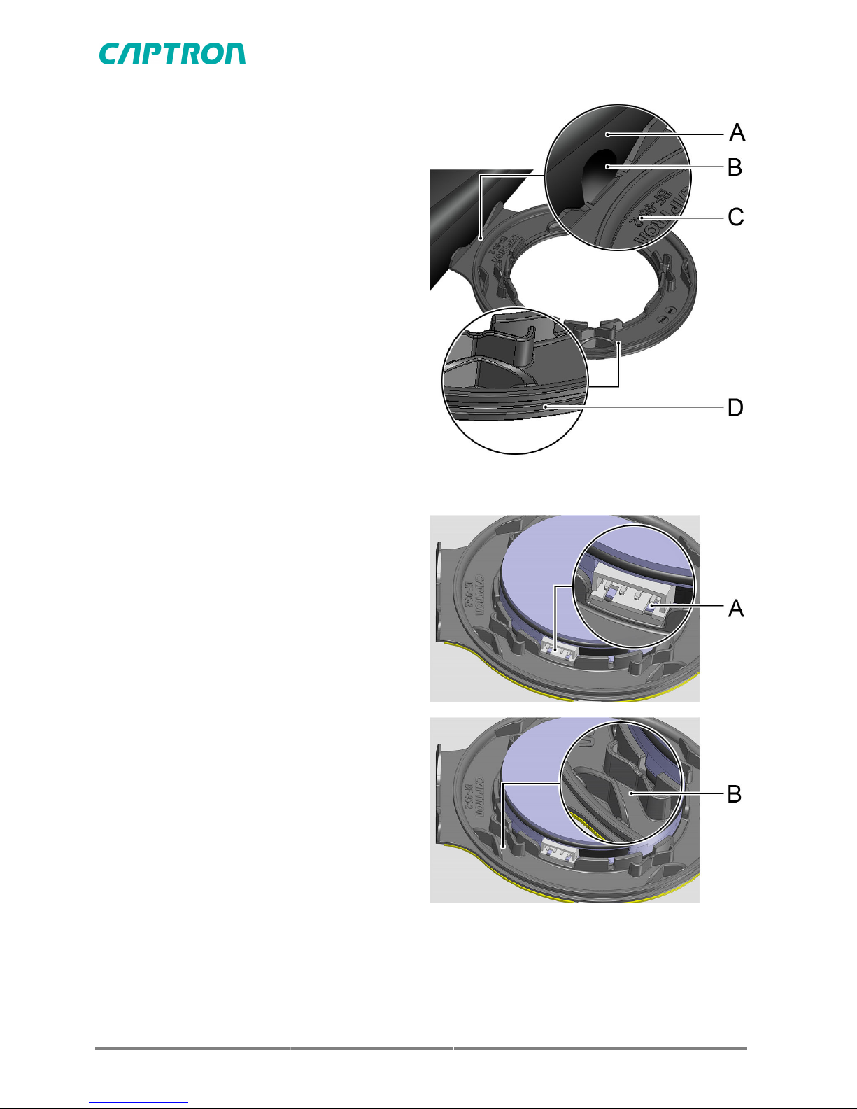
A Colored position ring
B Pane of glass
CHT5, single pane
CHT51, double pane
C Mounting flange BF-95-2
D SENSORswitch
E Colored cover ring AR5-2X_

CHT5 / CHT51 1.2 9/15
7 Assembly
7.1 Assembly, inside
7.1.1 Cleaning the surface
Requirements: The surface is level and sound.
For optimal gluing results, the surface must be cleaned thoroughly at the
position where the button will be located.
► Clean the surface with cleaning
cloth A.
► Dry the surface with a lint-free
cloth.
► Clean the surface with cleaning
cloth B.
► Dry the surface with a lint-free
cloth.
7.1.2 Assembling the mounting flange
NOTICE
Soiled bond areas prevent proper assembly!
4Protect the bond area from soiling.
4Do not touch the bond area.
4If the bond area has been touched or soiled, use a new mounting
flange.
10/15 1.2 CHT5 / CHT51
► Insert the supplied O-ring into
the groove (D) on the mounting
flange.
► Remove the protective film from
the mounting flange (C).
► Align the mounting flange (C)
to the hole (B), place it on the
profile of the glass frame (A) and
press on firmly.
7.1.3 Assembling the SENSORswitch
► Connect the SENSORswitch
electrically according to the
connection plan.
► Align the sensor element as
shown in the figure, paying
attention to the direction of the
symbol. The recesses on the
plug (A) must be facing the pane
of glass.
► Press the sensor element into
the mounting flange and check
whether the sensor element is
flat on the pane of glass.
► Lay the fastening cable between
the ridges (B).
This manual suits for next models
1
Table of contents
Other Captron Accessories manuals


