Captron CHT3 Series Reference guide

Conguration help for SENSORswitch series CHT3-4
82140 Olching, Germany
Johann-G.-Gutenberg-Str. 7
www.captron.com
CAPTRON Electronic GmbH
CAPTRON Electronic GmbH Johann-G.-
Gutenberg-Str.7
82140 Olching, Germany
www.captron.com
Tel +49(0)8142-4488-0 • Fax +49(0)8142-4488-100 • info@captron.com
Geschäftsführer: Reinhard Bellm, Petra Bellm, Philip Bellm • München HRB 70962 • USt.-ID Nr.: DE 129 310 850
Configuration help for SENSORswitch
series CHT3-4
Content: Short description / Technical data (Page 1)
Configuration help Page 2)
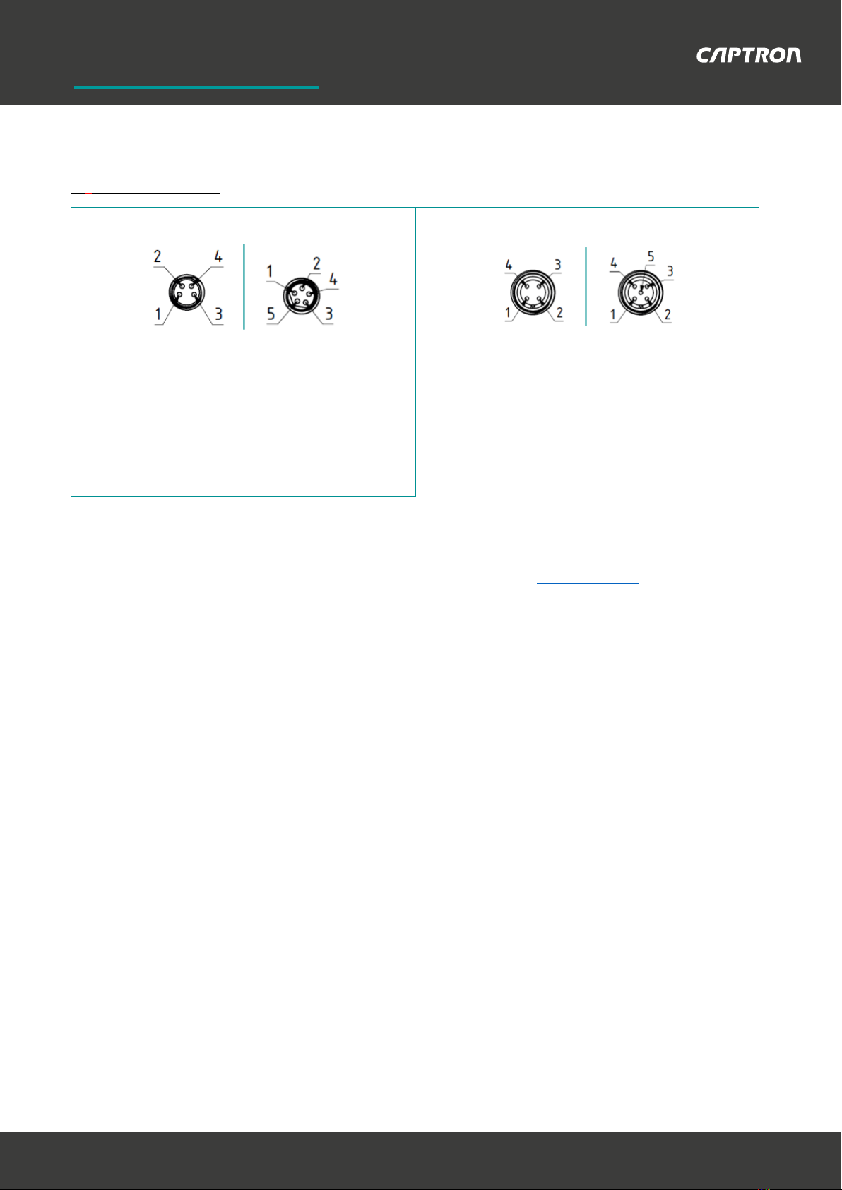
Additional information / Connection diagram (Page 3 & 4)
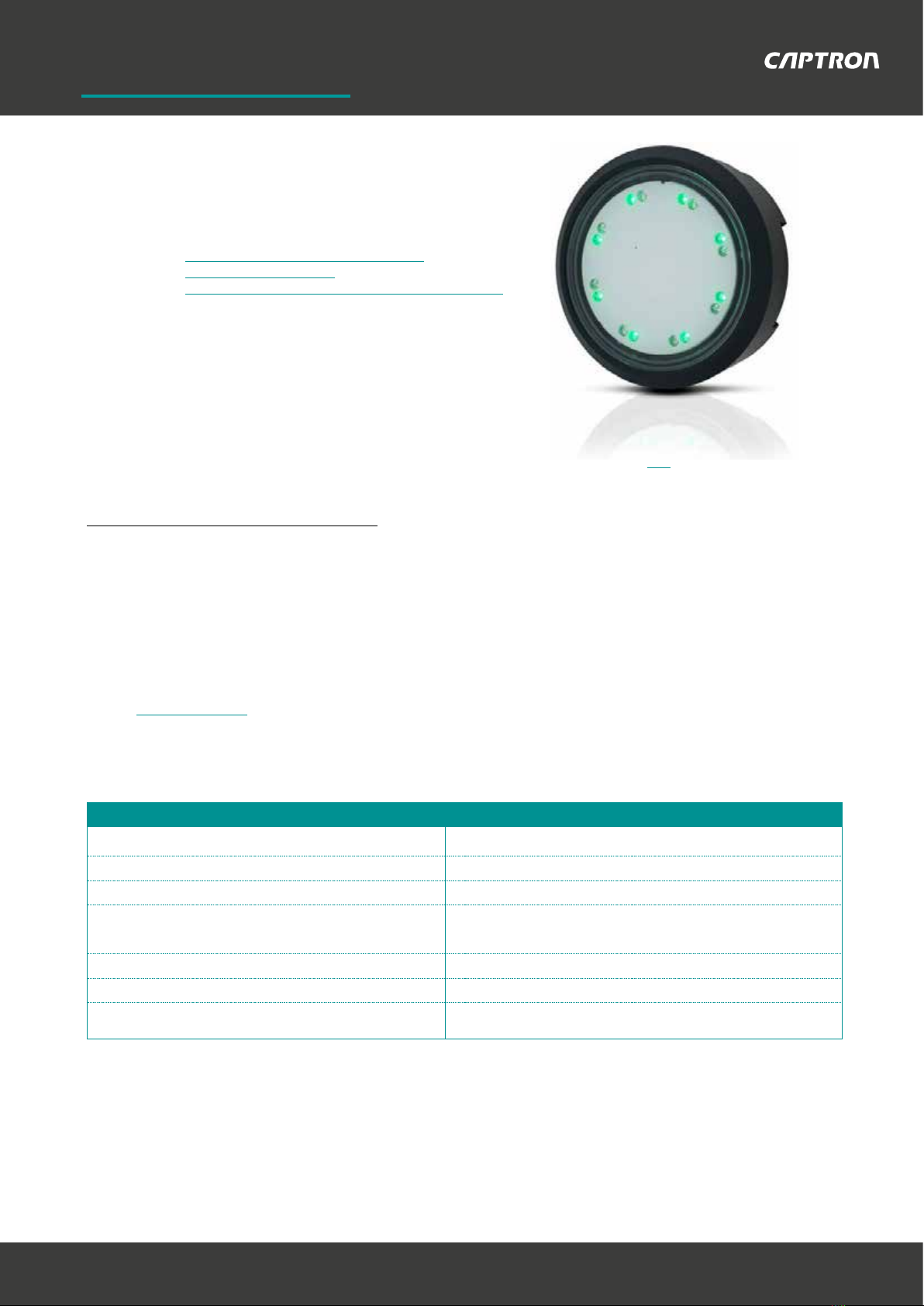
Different shapes, installation depths and plug-in connections mean that the
CHT3 series is suitable for a wide range of uses.
The CHT3-4 series has been developed for mounting = Ø 22.5mm.
So this SENSORswitch series can be installed in Siemens or Möller housings,
for example. The mounting is done by a knurled nut which is included in the delivery.
The main area of application for the CHT3-4 SENSORswitch series is mechanical
engineering and plant building.
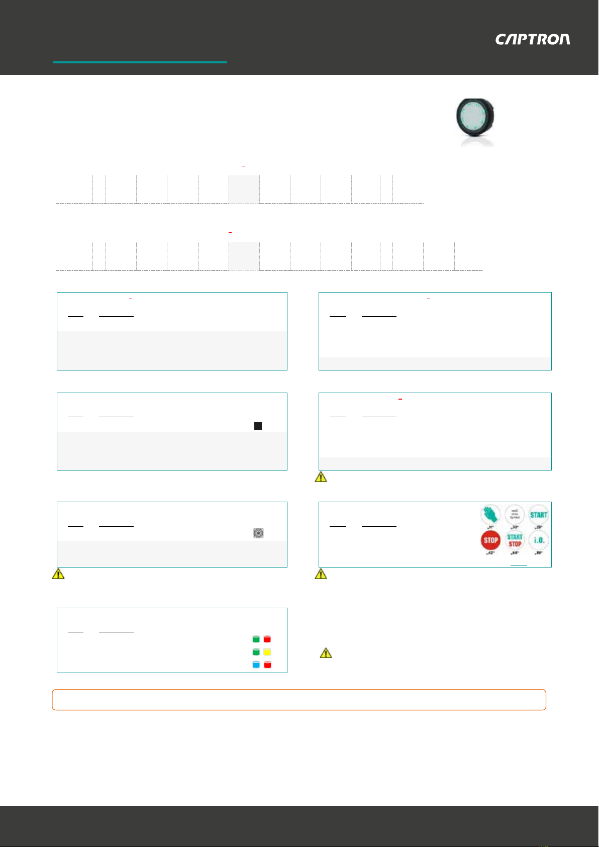
The customer can choose from a wide range of available symbols for the switch surface (symbol list: Link). In addition to the optical
feedback by 16 bright LEDs, the SENSORswitches can be ordered with a tactile feedback by vibration.
Please find below the most important features listed:
- Ø 50 mm total diameter - 25mm height
- For 22,5mm mounting holes - Customization through symbols
- M18x1 knurled nut mounting - Optional: Tactile feedback (Vibration)
CAPTRON can provide individual advice to enable you to choose the perfect
product from the CHT3 series for the required specifications and applications.
Please contact us:
Phone: +49 (0)8142 / 44 88 –160
E-Mail: sales@captron.com
Technical data at 24 V and 20 °C:
Supply voltage: DC 24V DC (16,8 … 32V) Short-circuit protection:
Short-circuit and overload
protection
Load current: Max. 400 mA Voltage drop: max. 3 V at 400 mA
Output: PNP-NO (NPN-NO optional) Current consumption: max. 30 mA at 24V DC
Output signal:
approx. 300ms (Option „Dynamic“)
Operation temperature:
-30 … +80°C (Dynamic)
Permanent signal (Option „Static“) 0 … + 55°C (Static)
LED 1: 8 green LEDs Degree of protection (IP): Frontside IP69K
LED 2: 8 red LEDs Type of operation: Capacitive
Reverse polarity
protection:
Protection of all lines Operation force: No operation force required

Conguration help for SENSORswitch series CHT3-4
82140 Olching, Germany
Johann-G.-Gutenberg-Str. 7
www.captron.com
CAPTRON Electronic GmbH
CAPTRON Electronic GmbH Johann-G.-
Gutenberg-Str.7
82140 Olching, Germany
www.captron.com
Tel +49(0)8142-4488-0 • Fax +49(0)8142-4488-100 • info@captron.com
Geschäftsführer: Reinhard Bellm, Petra Bellm, Philip Bellm • München HRB 70962 • USt.-ID Nr.: DE 129 310 850
2
Type code 1 –with output signal Dynamic 1:
CHT3 - 4 6 - / - /
Example: CHT3 - 4 5 6P - H / TG - SR
Type code 2 –with output signal Static 1:
CHT3 - 4 6 - / - / ST /
C1 –Mounting 2
C2 -Type of connection 4
Code
Description
Code
Description
4
Ø 60mm, M18 thread; for mounting Ø 22.5mm
5
Connector M8
-
-
7
Single strands 200mm with ferrules
- -
8 Connector M12
- -
- -
C3 –Colour of housing
C4 -LED control 3/ Numbers of pins / Output
Code
Description
Code
Description
6 Traffic black (RAL 9017)
P Semi-Automatic / 4-pin / PNP-NO
- -
B Manual / 5-pin / PNP-NO
-
-
N
Semi-Automatic / 4-pin / NPN-NO*
-
-
- -
* currently only available with connection type "5 - connector M8"!
O1 –Option 1 / Tactile feedback
C5 -Symbol on switch surface
Code
Description
Code
Description
V Tactile feedback (vibration) *
30 White surface
-
H
Hand (green on white)
-
For further symbols please see our Symbol list (Link)*
*only available with connection type „7 –single strands“ (LED control „P“ * all symbols marked as „Standard“ are already available from
/ „B –Manual“) or „5 –connector M8“ (LED control „P - Semi-Automatic“) 1 pieces / order up without any surcharge.
C6 –LED colours (LED1 –LED2)
Code
Description
TG-SR
Green (LED1) / Red (LED2) - Standard
TG-YW
Green (LED1) / Yellow (LED2)
*
*currently only available with the LED control "Semi-Automatic“
BU-SR Blue (LED1) / Red (LED2) *
as standard!
- - - Please note the additional information and explanations on the following pages. Thank you! - - -
C1
C2
C3
C4
O1
C5
C6
O2
C1
C2
C3
C4
O1
C5
C6
O2
Configuration help CHT3-4

Conguration help for SENSORswitch series CHT3-4
82140 Olching, Germany
Johann-G.-Gutenberg-Str. 7
www.captron.com
CAPTRON Electronic GmbH
CAPTRON Electronic GmbH Johann-G.-
Gutenberg-Str.7
82140 Olching, Germany
www.captron.com
Tel +49(0)8142-4488-0 • Fax +49(0)8142-4488-100 • info@captron.com
Geschäftsführer: Reinhard Bellm, Petra Bellm, Philip Bellm • München HRB 70962 • USt.-ID Nr.: DE 129 310 850
3
Additional information & explanations on the previously described configuration items:
to 1):
Output signal - Dynamic: The output signal is time-limited to 300ms, independent of the duration of actuation.
- Static: The SENSORswitch switches as long as the switch surface is touched (= permanent signal).
to 2) / Mounting & dimensions
„4“ -M18 thread; for mounting Ø 22,5mm
Legende:
(A) = Sensor element
(B) = Knurled nut
to 3) / LED control & connection diagrams:
LED-control - Semi-Automatic (P / N): LED1 (e.g. green / operating state) can be controlled separately.
When the SENSORswitch is actuated, LED1 goes out and LED2 (e.g. red /
switching state) lights up
- Manual (B): Both LED1 and LED2 can be controlled separately as required.
Connection diagram:
Connection diagram „P“ Connection diagram „B“ Connection diagram „N“
PNP-NO // Semi-Automatic PNP-NO // Manual NPN-NO // Semi-Automatic
- - - PLEASE TURN OVER - - -

Conguration help for SENSORswitch series CHT3-4
82140 Olching, Germany
Johann-G.-Gutenberg-Str. 7
www.captron.com
CAPTRON Electronic GmbH
CAPTRON Electronic GmbH Johann-G.-
Gutenberg-Str.7
82140 Olching, Germany
www.captron.com
Tel +49(0)8142-4488-0 • Fax +49(0)8142-4488-100 • info@captron.com
Geschäftsführer: Reinhard Bellm, Petra Bellm, Philip Bellm • München HRB 70962 • USt.-ID Nr.: DE 129 310 850
4
to 4) / Types of connection:
Connector M8 („CHT3-_5_...“)
4-pin 5-pin
Connector M12 („CHT3-_8_...“)
4-pin 5-pin
Single strands 200mm („CHT3-_7_...“)
Single strands 200mm with ferrules
(Wire end ferrules with plastic collar DIN 46228; wire cross-section
strands 0.25 mm²)
4-pin 5-pin
You need support with the configuration?
Our internal sales team will be happy to advise you on this (Tel.: +49 (0)8142 / 44 88 –160; [email protected]om)
You need data sheets and/or 3D data?
Please also contact our internal sales department. Thank you.
Version 1.0 / data status: 12.03.2020
Other manuals for CHT3 Series
1
This manual suits for next models
1
Other Captron Accessories manuals
Popular Accessories manuals by other brands

MAGINON
MAGINON MPP 3000 AL user manual

fafnir
fafnir 81 D-Ex Series instructions

TQ Environmental
TQ Environmental GD133 operating manual

Arlec
Arlec DCS01 installation instructions

Fire-Lite Alarms
Fire-Lite Alarms CP350 Installation and maintenance instructions

Volirium
Volirium Flytec Balloon Live Sensor user manual