Caratec CASAT-5065 User manual

Caratec Sat
CASAT- 5 0 6 5
CASAT-5085/T
Instruction manual

2
Made in Europe
CARATEC by Calearo ist ständig um weitere Verbesserung seiner Produkte bemüht.
Optische und technische Änderungen bleiben vorbehalten.
CARATEC by CaleA
Copyright CARATEC by Calearo, / via Bacchiglione 49, 36033 Isola Vicentina (Vi) Italy - 2015. Alle Rechte vorbehalten.

3
Dear Customer,
Congratulations on your choice of the CA-SAT CARATEC
by CALEARO parabolic satellite antenna, an innovative
and technologically advanced system for the static
reception of TV signals from satellites. This automatic
tracking antenna, made from top quality components
and controlled by sophisticated software ensures the
following:
Broadcast Satellite)
vehicle
CA-SAT is a product designed, developed and
assembled in Europe.
CONGRATULATIONS

4
Basic principles
ATTENTION
the installation must be performed
by qualified personnel, in particular
for the operations of appliance’s
tightening, cable routing and electric
connections.
ATTENTION
carefully read all safety regulations.
failure to observe the regulations
reported below can cause serious
damage to people or objects.
ATTENTION
before proceeding with any operation
regarding the installation, always
disconnect the primary power supply
(vehicle battery).
ATTENTION
before moving the vehicle, always check
that the antenna is closed even if the
acoustic signal is off.
An essential safety factor is appropriately executing
assembly operations and electrical connections.
Strictly adhere to assembly conditions and operations.
Using the manual
We suggest that you carefully read this manual
before installing and using the CA-SAT antenna and
to adhere strictly to what is included in it, most of
all that which concerns safety and environmental
protection.
This manual contains complete instructions for
correctly installing the CA-SAT system.
The most important information is highlighted inside
the manual by the following icons:
Information regarding system procedures,
operation and specification
Information regarding electrical safety
Information regarding system installation
Useful suggestions
Correct operation of the system
For safe installation of the system and the correct
performances of all the functions of the product, you
must adhere strictly to the instructions in this manual.
This includes travelling in the vehicle once the CA-SAT
has been installed.
CA-SAT is a system designed for use on stationary
campervans and motorhomes and it can receive
TV and radio signals transmitted by geostationary
satellites.
The system can automatically track the geostationary
satellites which transmit a QPSK modulated signal,
according to the DVB-SI EN 300 468 Standard.
The product is designed to be powered by the
vehicle. If power is supplied from a 24V or a 220V
AC source, then a suitable 12V DC stabilised voltage
adaptor must be used.
The maximum recommended speed for vehicles
It is important to fold the antenna before starting
Please note that the following actions can
harm the system, compromise electrical safety and
inappropriate assembly/installation/connections;
use of tightening equipment not described in this
manual;
use of the system in a not appropriate way or
designed;
components or accessories by unauthorised
personnel;
failure in adhering to the installation and safety
operations reported in this manual.
WARNINGS

5
Cautions
do not modify the system by eliminating or adding
any component.
do not use any other parabolic dish or LNB
converter apart from the ones supplied.
in order to guarantee the correct functioning of the
used to carry out the installation of the equipment.
Improper installation can cause damage to the
vehicle and to the equipment.
appropriate strength and stability.
it is important that during installation and use
the instructions in this manual are always strictly
followed.
no maintenance is normally required, but do not
open the protective covers. If any investigation
employed.
once the equipment is installed on your vehicle, for
parts cleaning and maintenance do not use either
a car wash or high pressure cleaner.
the antenna has been designed to sustain a
wind resistance of 120 km/h. If strong winds are
encountered, we recommend that the antenna
is closed in order to prevent any stress to the
in wintery conditions remove any snow or ice from
the antenna before opening. This will prevent any
damage and battery drain.
the equipment has been designed to operate with
external temperatures between
- 15°C and + 45°C.
Its use outside this range can cause damage or
malfunction.
ensure that the vehicle battery is fully charged.
A voltage drop below 11V DC will prevent the
antenna from lifting and the correct functioning of
the system.
General safety rules
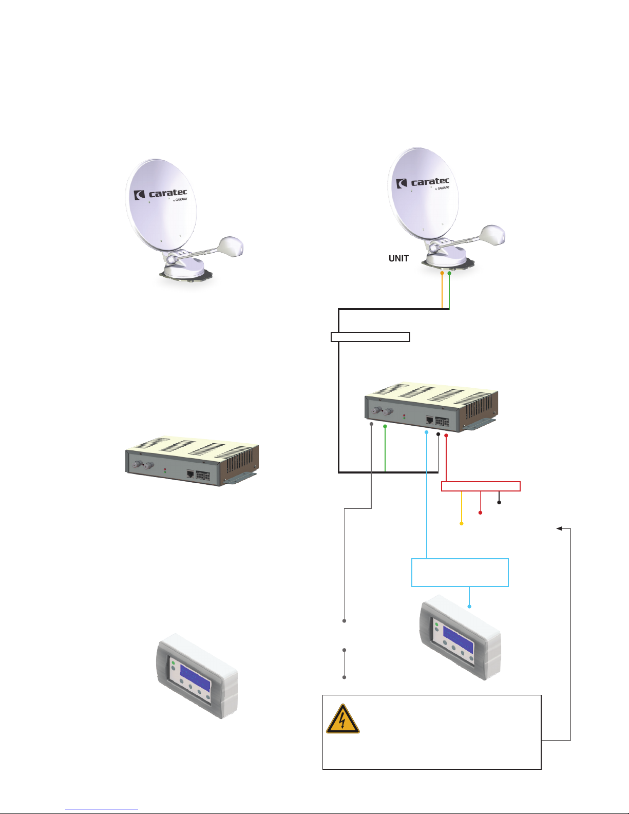
EXTERNAL UNIT
Before operating the external unit and opening the
parabolic antenna, ensure that the entire working
area of the antenna is free from any obstacle which
could prevent its lifting and free rotation.
The equipment should only be powered by a 12V DC
voltage directly from the main battery using cables
with a minimum sectional area of 2.5 mm.
If using an auxiliary 12V power supplier and not the
vehicle battery, make sure that this equipment is
stabilised and can supply at least 10A. Use of non-
stabilised power supply can cause malfunction and
system failure.
Before activating the equipment, ensure that nobody
is close the antenna, could obstruct the movement or
be harmed during its opening or rotation.
SYSTEM ASSEMBLY
During assembly, please observe the following
safety measures:
ensure that the system is not powered until the
installation is completed;
ensure that the vehicle roof is strong enough to
carry the equipment;
ensure that the roof is free from obstruction or
people within the operational area of the antenna;
ensure that there is safe access to the vehicle
roof area for installation and suitable equipment is
used e.g. ladder.
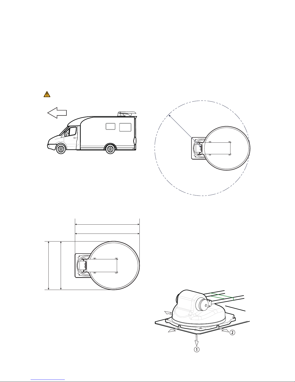
According to Article 19/2; 30 C; 32 (2) and to the
documents is necessary if:
the external unit is installed 2 metres above the
ground;
the external unit does not extend laterally from the
the total height of the vehicle and the external unit,
once closed, does not exceed 4 metres.
WARNINGS

6
CONTENTS OF THE PACKAGE
MOTORISED EXTERNAL UNIT including:
AMotor assembly - BTightening plate
CLNB converter - D4m Control cable
REFLECTOR ASSEMBLY
MAN MACHINE INTERFACE (MMI)SYSTEM CONTROL UNIT (CU)
POWER SUPPLY CABLE
CONNECTION CABLE
between Control unit and
Man Machine Interface
n.6 STAINLESS STEEL
F CONNECTOR
AND F TYPE KEY
CONNECTOR
INSTRUCTION
MANUAL
ALLEN KEY 6mm
ATTENTION:
OpERATE wiTh CAuTiOn
Remove the external unit from the packaging only by lifting it by the aluminium plate. Never lift it on the LNB
holding arm.
Never pull, lift, turn or manually force the LNB holding arm. Its movement must be activated only and exclusively
with the motor.
Before proceeding with the installation, check the integrity of the parabolic antenna and the presence of all
accessories indicated in the instruction manual. CARATEC by Calearo is not liable for damage caused by the
transport or the lack of components in the package after the installation.
A
B
C
D

7
THE SYSTEM
Components of the system
EXTERNAL UNIT
The external unit, to be installed on the roof of
the vehicle, includes the motor assembly with the
the LNB (Low Noise Block) converter. Power supply,
satellite signal and control unit commands go through
the connection cable.
The Control Unit is the interface between the external
unit and the Man Machine Interface (MMI). It provides
the power and receives/sends data to the external
unit. It contains the antenna movement management
electronics and processes the digital information
received by the satellites. It can be updated, if
necessary, by authorised technical personnel, by
simple operations.
The Man Machine Interface (MMI) allows the user to
access the system and its functions
Diagram
Control cable
Power supply cable
(black)
+12v (red)
(orange)
CONNECTION cable
between Control unit and
Man Machine Interface
SATELLiTE
RECEivER
Tv
to avoid moving the vehicle while
unintentionally the antenna is in open
position, it is strictly necessary to
connect the orange wire to +
12
vdc
switched positive voltage, which is only available
when the ignition is turned on.
EXTERNAL UNIT
CAUTION

8
EXTERNAL UNIT INSTALLATION
Available models
The new range of motorised satellite antennas by
CARATEC by Calearo are technologically innovative
and have an advanced design.There are two sizes,
Ø 65cm and Ø 85cm, and these are fully capable of
satisfying any reception requirement.
Equipment for the assembly
The CA-SAT system has been designed for simple and
fast installation.
For installation you need:
Allen key 6mm
(included in the carton)
Socket wrench 10mm
Phillips screwdriver
Electric drill
with Ø 18mm bit
Epoxy or polyurethane
structural adhesive
Industrial cleaner to
clean the mounting
base
External unit
c
arefully read all safety regulations.
failure to observe the general safety
regulations
(
page
5)
can cause serious
harm to people or objects
.
ATTENTION
do not remove the green safety strap on
the lnb holding arm. only remove it after
mounting the reflector assembly on the
base.
ATTENTION
using only adhesive is not enough to
guarantee an adequate adherence of the
system to the surface, so we suggest the
use of suitable anchoring screws.
ATTENTION
in case the vehicle exceed the allowed
maximum height because of afailure to
close the antenna, there is ahigh risk of
accidents or damaged.
the driver of the vehicle is the only liable.
ATTENTION
It is important that the vehicle roof is structurally strong
enough to resist the mechanical stress caused by the
antenna.
stability, use the aluminium sheet plate provided in the
Driving
Direction

9
Choose the mounting point on the vehicle roof
(possibly on one side of the roof) by taking care that:
the LNB holding arm is directed to the rear of the
vehicle, therefore opposite to the driving direction
If this is not respected, it invalidates the
warranty.
the mounting surface has the minimum possible
inclination and, to guarantee safe gluing, the
tightening plate is compensated by the adhesive
seal.
there is enough space to install the external unit
all elements in the roof (e.g. climate controls,
liftable roofs, roof bars etc.), which can interfere
with the functioning of the external unit while
moving, are out of the movement area of the
the chosen point, related to the positioning of the
internal units, matches the routing of the cables for
their connection.
cable
Once the mounting point has been chosen, select the
way of routing the cable inside the vehicle:
1. Passing the hole on the roof q, directly under the
motor assembly, in the middle of the tightening plate
2. Side exit w, by using one of the three orthogonal
5), in order to take advantage of the cable seals
EXTERNAL UNIT INSTALLATION
DRIVING DIRECTION
Ø 65cm 860mm
Ø 65 700mm
Ø 85 850mm
Ø 85 1060mm
r. 750mm
r. 950mm
TELSAT 65
TELSAT 85

10
Unscrew the 4 perimeter nuts of the motor assembly
q, by using a 10mm socket wrench, leaving inserted
the respective bolts wand separating it from the
tightening plate e
Rest the plate on the point chosen for the installation,
driving direction again, and mark the perimeter of
the mounting plate, the central hole position and the
position of the perimeter screws.
If you prefer to let the control cable pass through the
the central hole of the plate.
Sandpaper and thoroughly clean both the roof, in the
area chosen for the installation, and the lower part of
the tightening plate to eliminate any trace of grease or
dust. For cleaning the mounting plate and the roof, use
the special cleaner suggested by the manufacturer of
the adhesive.
After the cleaner has dried, apply an uniform layer of
epoxy or polyurethane structural adhesive (e.g. Loctite
A&B, Loctite Terostat NS939, 3M DP105, 3M DP125,
at room temperature, following the instructions.
Put, in the previously cleaned area (paying attention
to the vehicle driving direction), the plate on the roof
distribution of the adhesive on all the surface and
maximum adhesion.
If necessary screw in the 6 additional perimetral
tightening screws q (provided). Take care that
the 4 perimetral bolts w are available, as they are
necessary to tighten the motor assembly. The choice
of screw type must be done based on the thickness
and the kind of material which the vehicle roof is made
Stretch a mastic cord all around the edge of the
tightening plate, and around the 6 perimetral screws,
Observe the drying time necessary for the adhesive
(as indicated by the manufacturer).
Install the motor assembly on the tightening plate by
passing the control cable from the desired position
(see step 3. Choosing the route for the control cable).
Inside the motor assembly do not attach the cable
to the vehicle roof with straps or cable seals. The
cable must be free to move during the rotation of the
antenna.
EXTERNAL UNIT INSTALLATION
Driving
Direction
VEHICLE ROOF
MASTIC TIGHTENING PLATE
Driving
Direction

11
Put the motor assembly qon the tightening plate.
Lock it by screwing the 4 self-locking tightening nuts
that were previously removed w
If the antenna has been directly installed on the
vehicle roof, without using the tightening plate, or
if you chose to make the control cave go through
the central hole under the antenna, and to properly
secure the installation stretch a silicone mastic cord all
around the edge of the motor assembly base and the
Thermoforming parts (motor carter) are covered
removed after the parabolic antenna has been
installed.
Using the 6mm Allen key provided, carefully
unscrew the lateral screws from the motor assembly
q. Move the locking ferrules away from the motor
assembly to create enough space to allow the
w
qinto its seat.
Reposition the locking ferrules in their seat, by turning
w
the 6mm Allen key provided in the carton.
EXTERNAL UNIT INSTALLATION

12
INTERNAL UNITS INSTALLATION
carefully read all safety regulations.
failure to observe the general safety
regulations
(
page
5)
can cause serious
harm to people or objects
.
ATTENTION
Bring the Control cable from the External unit to the
Control unit.
Inside the motor assembly do not attach the cable
to the vehicle roof with straps or cable seals: the cable
To avoid movement when the vehicle moves, along
the cable tighten it to the walls by using standard
tighteners, available in the supermarket.
If the Control cable is too long, you can roll it up near
the Control unit.
Select an area, which is easily accessible inside the
vehicle, in a space which is protected against dust,
moisture, possible contact with liquids and which is big
enough to have an adequate ventilation. Install the unit
in a horizontal or vertical position.
Select an area, which is easily accessible and visible
from inside the vehicle, which is at a maximum
distance of 1 (one) metre from the Control unit. The
unit can be installed as a built-in in a 4-way junction
box (normally referred to as model 504), or externally,
by using the plastic box provided.
Provide the system with an adequate power supply of
12V DC. Ensure that the battery charge is optimal: a
voltage drop (min 11.7V DC) will prevent the antenna
from lifting and the system from functioning correctly.
Connect the black wire of the Power cable to the
negative, the red wire to the positive of the power
supply source, and the orange wire to a switched
positive voltage of +12V DC which is only available
when the ignition key of the vehicle is turned on
(IGNITION).
For distances between the power supply point and
the Control unit between 1 and 6m use a cable with
a minimum sectional area of 2.5mm2. For longer
distances we suggest to use cables with a sectional
area of 4.0mm2.
Normally the power supply cable coming from the
battery, already used to power the other equipment on
sectional area to guarantee the correct power supply
voltage to the system, thus preventing correct
functioning. We suggest installing a new power supply
line expressly dedicated to this task by installing a
primary protection fuse with a value between 10-15A.
The antenna system is provided with a safety
electronic control to prevent the vehicle moving while
unintentionally leaving the antenna in open position.
To allow this control to function, connect the orange
wire of the power cable to a switched positive voltage
of +12V DC, only available when the ignition key of
the vehicle is turned on (IGNITION). The control, as
soon as the vehicle engine is turned on, automatically
brings the antenna to the rest position (closed), which
operation.
The system is provided with pre-connected
cables. The only one which needs the connector to
be installed is the Sat coaxial cable: assemble the
connector F on the coaxial cable as shown in the
You should not cut the pre-connected cables
provided in the carton.
15
105

13
ELECTRIC CONNECTIONS
ATTENTION
when the system is powered, aself-
test is started. if an error message
appears on the display, together
with an intermittent beep, see the
troubleshooting section in this manual.
ATTENTION
if the primary power supply is missing
the antenna remains positioned where it
is. check that the system has completed
the closing procedure before removing
the primary power supply from the
system.
CAUTION
before inserting the power connector,
check that the connections between the
internal units and the external unit are
correct.
CAUTION
the control unit power supply is
protected with in line 5a fuse. in the
case of the fuse breaking you need
to solve the cause of the failure and
replace the fuse.
never remove or exclude the fuse.
CAUTION
to avoid moving the vehicle while
unintentionally the antenna is in open
position, it is strictly necessary to
connect the orange wire to +
12
vdc
switched positive voltage, which is only
available when the ignition is turned on.
1. Insert the connector of the Control cable coming
from the External unit into the corresponding
connector [
antenna motor
] in the Control unit.
2. Connect the coaxial cable coming from the External
unit to the connector F [
lnb
] of the Control unit.
3. Insert the connector RJ45 available on one end
of the Connection cable into the corresponding
connector in the User interface module.
4. Insert the connector RJ45 available on the other
end of the Connection cable into the corresponding
connector [
display
] in the Control unit. If the data
securely.
5. Connect a coaxial cable to the connector F
[
receiver
] of the Control unit. This cable is used for the
connection of the satellite receiver.
6.
turned on (IGNITION).
7.
(+12V).
8.
(Ground).
Make sure that this connection is always available
(e.g.: avoid a switch opening the connection).
9. Insert the connector of the Power cable into the
corresponding connector [
power
12
vdc
] in the Control
unit.
EXTERNAL UNIT
TO THE SATELLITE
RECEIVER
IGNITION (orange)
+12V (red)
GROUND (black)

14
HOW TO START
MAN MACHINE INTERFACE
LED
system or to enter
stand-by mode
red = stand-by
yellow = operating
green = OK
blinking = folding down
BUTTON
ENTER BUTTON
BUTTON
Previous setting
ESC BUTTON
To enter the Menu or
to cancel the selection
BUTTON
Following setting
no audio
intermittent beep
single beep
Please check all the connections and then supply
voltage +12V DC to the system.
The MMI turns on, for some seconds, for a short time,
and performs a self-test procedure by verifying the
correct connection and communication among the
various components of the system. The MMI displays:
when xx indicates the Hardware, Firmware and Software
versions.
WARNING: In case of connection problems a
warning message will be displayed with an intermittent
MESSAGES” section.
+12V DC supplied) of the complete system without
any previous pointed satellites.
Press and hold the [ON/OFF] button, until the beep
starts and the yellow led lights up.
Release the button.The green led will light up and the
MMI will display:
setting” procedure and MMI will display:
in the zero reference position and the MMI will display:
Press the [ESC] button and select the favourite item in
the Menu list (e.g.: Auto Pointing).
ON-OFF
STAND-BY
CALEARO
CA-SAT
CALEARO
[xxM Fx.x Hx.x]
LED
LED
Dish closed
LED
LED
Resetting......
LED
ESC continue
LED

15
Signal reception
The signals from the main satellites, available in
Europe, approximately come from a southerly
direction. Please be sure that no obstacles are
between the antenna and the satellites (e.g.: buildings,
mountains, trees, etc..), in that case the antenna will
not be able to correctly point to the satellite in order to
guarantee the best reception of television programs.
Before operating the antenna, please verify that
no obstacles (e.g.: branches, heating systems,
air conditioners, etc..) can prevent the movement,
opening and rotation.
The weather conditions like heavy rain, storm clouds,
decrease the quality of the received signals.The signal
may be temporarily absent caused by heavy rain or
snow on the LNB and on the dish of the antenna.
In some European areas, the satellites do not
intensity to be received by antennas of this size (dish
ø 65cm or ø 85cm), so the pointing procedure and the
channel research may not be successful. For more
information of the satellite coverage please consult
professional websites or professional magazines.
Press and hold the [ON/OFF] button until a beep starts
and the yellow LED lights up.
Release the button.
A. If previously no satellite has been pointed at,
display:
Press the [ESC] button and select the favourite item
in the Menu list (e.g.: Auto Pointing).
B. If previously a satellite (e.g.: HotBird, Astra...) has
been pointed at, the antenna will point the satellite
whose name will be displayed on the MMI.The in-
The MMI will display:
Where satellite name is the name of the latest
satellite pointed at (e.g.: Astra 19,2E).
After the pointing procedure
If the position points at the right satellite, the MMI
will display:
will display:
After 10 seconds the system automatically will enter
the Stand-by mode, the BEEP will start once and the
red LED will light up.
before operating the system, please
verify that no obstacles are between
your position and the southerly
direction.
ATTENTION
DAILY USE
SUD
LED
ESC continue
LED
ASTRA 19,2E
Found
LED
ASTRA 19,2E
Locked
LED
OK!
KO
satellite name
Searching...
LED

16
Or
If the position does not point at the right satellite,
the MMI will display:
then, after a small checking procedure, automatically
the system will start the pointing procedure. The in-
The MMI will display:
Once the satellite is pointed at, the MMI will display:
will display:
After 10 seconds the system automatically will enter in
Stand-by mode, the BEEP will start once and the red
LED will light up.
This feature is really useful, because in case the
system is switched OFF and then ON, the antenna will
autopoint the last satellite pointed at.
C. If the position points at the right satellite, the MMI
will display:
After 10 seconds the system automatically will enter
the Stand-by mode, the BEEP will start once and the
red LED will light up.
If the system is ON, press and hold the ON-OFF
button, until the BEEP starts and the red LED lights up.
Then the MMI will display:
Release the button.
When the red LED is ON the system is in Stand-by
mode.
If the ON-OFF button is hold on even after the
red LED lights up, the system folds down the antenna
(Sleeping Mode) and swtiches OFF.
This function allows the antenna to be folded down
manually (Sleeping Mode).
This function is available in Operating Mode not in
Stand-by Mode.
In Operating Mode press and hold the ON-OFF
button, the BEEP will start and the red LED will light
up, then the yellow LED will blink.The MMI will display:
Release the button.
The system will fold down the antenna (Sleeping
intermittent BEEP and by the blinking yellow LED. The
MMI will display:
Then the system will switch OFF.
DAILY USE
LED
LED
Closing dish...
LED
ASTRA 19,2E
Locked
LED
LED
ASTRA 19,2E
Found
LED
ASTRA 19,2E
Locked
LED
ASTRA 19,2E
Searching...
LED
ASTRA 19,2E
No signal
LED

17
Press the ESC button to enter the main Menu.The
MMI will display:
available:
the system automatically will point to the favourite
satellite previously selected by the user.
the user manually must set the Elevation and the
Azimuth in order to point to the favourite satellite.
Language
The user must set the proper language displayed
in the MMI.
Service
This protected area is dedicated to authorized
professional staff for settings and diagnostic
functions.
This function is exclusively available for the
service centres or authorised personnel and
protected by a 4-digit code.
The Service is a protected area, dedicated
to authorized professional staff for settings and
diagnostic functions.To guarantee Warranty
Terms only professional users should access this
area.
press the [ESC] button to exit the Menu.
Press the [ESC] button. The display shows:
to
Language.The MMI will display:
button to go back.
The MMI will display the languages available:
to the
favourite Language. (eg.: Italian)
*” is the previous selected language.
button to go back.
DAILY USE
Auto Pointing
Manual Position
LED
Auto Pointing
Manual Position
LED
Manual Position
Language
LED
English
Italiano
LED
*English
Italiano
LED

18
Press the [ESC] button.The MMI will display:
display the list of preset satellites:
to the
favourite satellite, e.g.: HOTBIRD 13E
the *is the previous selected satellite. Press the
[ESC] button to return to the Main menu.
The system automatically will start the pointing
procedure. The time of the pointing procedure can
the blinking yellow LED.The MMI will display:
Once the satellite is pointed, the MMI will display:
will display:
After 5 seconds the system will automatically enter the
Stand-by mode, the BEEP will start once again and
the red LED will light up on the User interface module.
Press the [ESC] button.The MMI will display.
to the
item Manual Position.
display the message:
where:
Elevation stands for the movement
+109 stands for the position
With the [ENTER] button modify the movement from:
Elevation lifting angle
Azimuth rotation angle
the position.
Press the [ESC] button to return to the Main menu.
To make the antenna movement more accurate,
when the movement control in elevation is activated,
the motor works in two speeds. Hold the button until
If the control of the position is lost, follow the
paragraph 3. Manual folding down).
DAILY USE
HOTBIRD 13E
Found
LED
HOTBIRD 13E
Locked
LED
Auto Pointing
Manual Position
LED
ASTRA 28E
ASTRA 23,5E
LED
* ASTRA 19E
HOTBIRD 13E
LED
HOTBIRD 13E
Searching...
LED
Auto Pointing
Manual Position
LED
Auto Pointing
Manual Position
LED
Elevation
+109
LED

19
To determine the adjustment parameters of the Skew angle for the LNB, identify your position in the map of
Europe and choose the corresponding parameters in the LNB Skew Table on page 20.
Europe map
Satellites transmit signals on two (horizontal and
vertical) polarisations which are orthogonal between
each other.
In order to optimise signal reception, the receiving
element Converter/LNB, which is mounted on the
parabolic antenna, must be positioned to be perfectly
aligned with the transmitted signals.When this does
angle”, in order to optimise its alignment with the
A typical example of this situation is the reception of
the following satellites: Astra 28,5E, Astra 19,2E or Hot
Bird 13E in countries like Portugal, Morocco, Turkey or
in Eastern European countries.
The Converter/LNB has been installed on the antenna
in a position that is suitable for allowing the correct
reception of the main satellites in most European
countries.
ATTENTION: The rotation of the LNB must not be
changed if the vehicle stays in the same geographic
area and you are receiving your signal from the same
satellite.
To access the LNB converter, remove the
protective plastic covers by unscrewing the three
parametric screws. Once the skew is adjusted, if the
vehicle stays in the same geographic area and is
receiving the same satellite signal, we recommend
that you screw that protective plastic covers back on.
ADJUST SKEW ANGLE
0°
1 2 3 4 5
6 7 8 9 10
11 12 13 14 15
16 17 18 19 20
21 22 23 24 25
26 27 28 29 30

20
LNB SKEW TABLE
rotate the converter
clockwise
–
rotate the converter
counter-clockwise
Map
position
ASTRA
28.2°E
ASTRA
23.5°E*
ASTRA
19.2°E
HOTBIRD
13°E
ASTRA
5,2°E
THOR
0.8°W
AMOS
4.0°W
ATLANTIC
5.0°W
ATLANTIC
12.5°W
HISPASAT
30°W
-9° -8° -6° -10° -6° -3° -2° -1° 3° 12°
2-5° -3° 0° -4° 0° 4° 5° 6° 10° 18°
-5° 3° 6° 2° 0° 9° 11° 11° 15° 22°
47° 10° 12° 7° 11° 14° 15° 15° 18° 23°
513° 15° 17° 12° 15° 17° 19° 19° 21 24
6-11° -8° -6° -10° -5° -1° 1° 2° 7° 17°
7-5° -2° 1° -3° -2° 5° 7° 8° 12° 21°
8-1° 2° 5° 1° 6° 10° 12° 13° 17° 25°
95° 8° 11° 7° 12° 15° 17° 18° 21° 28°
13° 16° 18° 14° 18° 21° 23° 24° 26° 31°
-14° -11° -8° -12° -6° -2° 1° 2° 7° 19°
-8° -5° -2° -4° -2° 6° 9° 9° 15° 25°
-4° 0° 3° 0° 6° 11° 13° 14° 19° 28°
6° 10° 13° 10° 16° 19° 21° 22° 26° 32°
16° 19° 22° 19° 23° 26° 28° 28° 31° 36°
-17° -14° -11° -13° -6° -1° 2° 3° 10° 24°
-12° -8° -4° -6° 1° 6° 9° 10° 16° 29°
-4° 0° 4° 2° 9° 15° 17° 18° 24° 34°
3° 8° 12° 10° 17° 21° 24° 24° 29° 37°
14° 18° 21° 18° 24° 27° 29° 30° 33° 39°
-24° -21° -17° -19° -11° -4° -1° 0° 9° 26°
22 -15° -11° -7° -8° 0° 7° 10° 11° 18° 32°
-8° -3° 1° 0° 9° 15° 18° 19° 26° 37°
24 5° 10° 15° 13° 21° 26° 28° 29° 34° 42°
25 17° 22° 26° 24° 31° 34° 36° 37° 41° 46°
26 -28° -25° -21° -22° -13° -5° 0° 1° 11° 30°
27 -22° -18° -12° -13° -3° -5° 9° 11° 20° 36°
28 -9° -3° 2° 3° 13° 20° 23° 24° 31° 43°
29 2° 8° 13° 14° 22° 28° 31° 32° 37° 46°
13° 19° 24° 23° 31° 35° 37° 38° 42° 49°
-33° -29° -26° -27° -17° -9° -4° -3° 8° 30°
-25° -19° -14° -13° -1° 8° 13° 14° 24° 41°
-11° -4° 3° 6° 18° 26° 30° 31° 39° 50°
1° 8° 15° 17° 27° 34° 37° 38° 43° 52°
14° 22° 28° 29° 37° 42° 44° 45° 49° 56°
*HD ready:
0°
This manual suits for next models
2
Table of contents
Other Caratec Antenna manuals
Popular Antenna manuals by other brands

Directive Systems & Engineering
Directive Systems & Engineering DSEDPM144-5LVA manual

Poynting
Poynting LPDA-0092-04 quick start guide

Andrew
Andrew 7.3-Meter ESA Installation, operation and maintenance

Motorola
Motorola PMAN4010 installation manual

Will Burt
Will Burt QEAM TM-21 operating manual

l-com
l-com HG2409Y quick start guide

COBHAM
COBHAM Sea Tel 2400 installation manual

Televes
Televes evoca 130990 Assembly / operation instructions / parts

General Dynamics
General Dynamics 500-0646 Operation manual

IKUSI
IKUSI FLASHD HDT530 quick start guide

Wilson Electronics
Wilson Electronics 301208 installation guide

Lancom
Lancom AirLancer IN-Q180 Mounting instructions