Deutsch
6
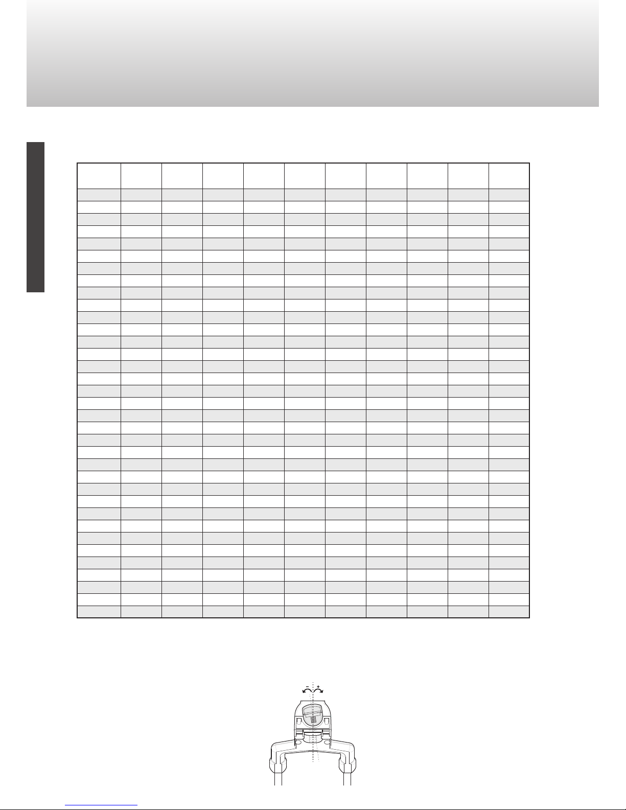
4. LNB Neigungswinkel
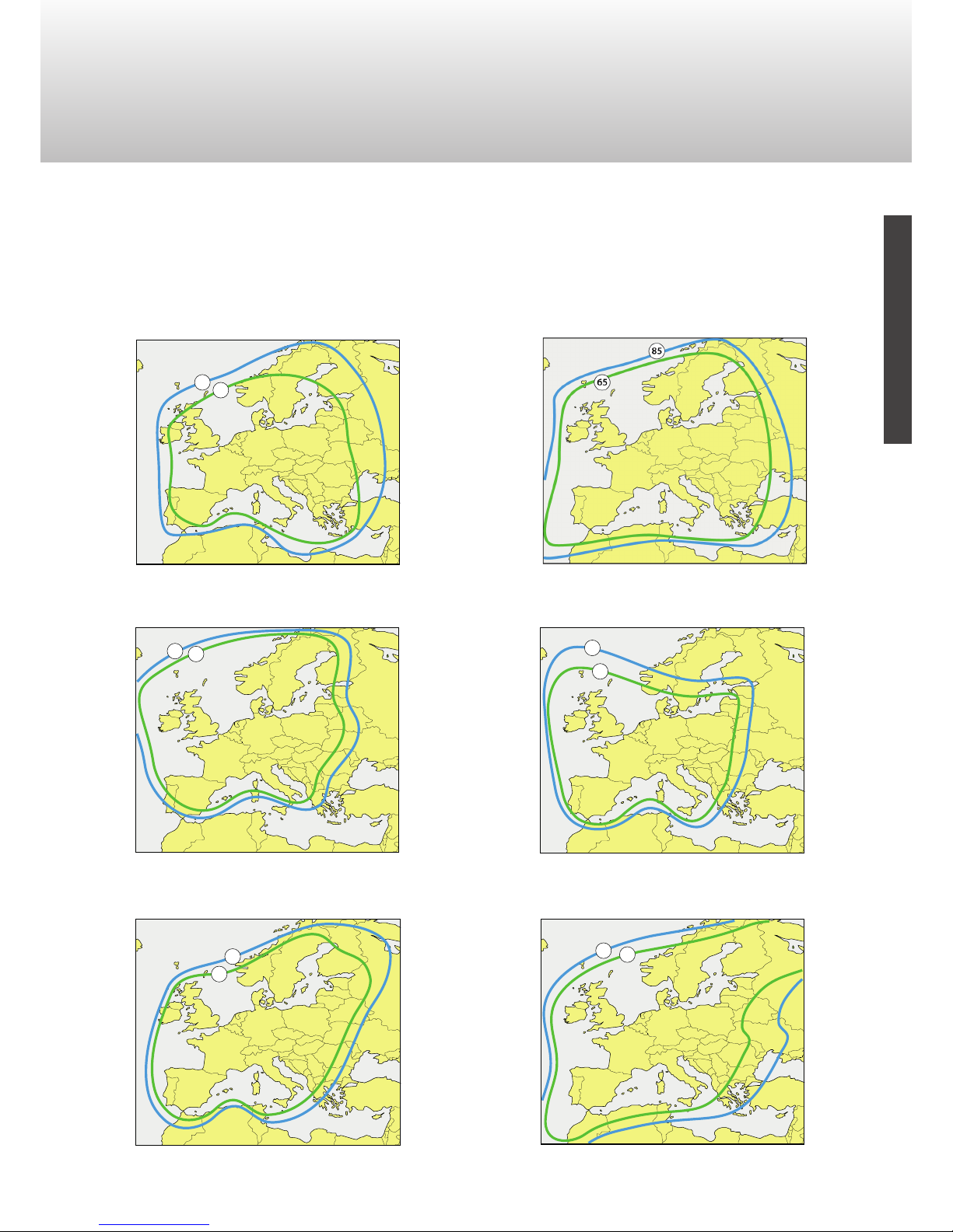
4.1 Tabelle
*HD ready: wenn die Übertragung von ASTRA 23.5° nur das DVB-S2 MPEG4 Format unterstützt, wählen Sie bitte
ASTRA 23,5° E HD am unteren Ende der Satellitenliste, um das System automatisch auszurichten.
Konverter gegen den
Uhrzeigersinn drehen
Konverter im
Uhrzeigersinn drehen
− +
0°
Posizione
Mappa
ASTRA
28,2°E
ASTRA
23,5°E
ASTRA
19,2°E
HOTBIRD
13°E
EUROBIRD
9°E
THOR
0,8°W
AMOS
4°W
ATLANTIC
5°W
ATLANTIC
12,5°W
HISPASAT
30°W
1 -9° -8° -6° -10° -8° -3° -2° -1° 3° 12°
2 -5° -3° 0° -4° -2° 4° 5° 6° 10° 18°
3 -5° 3° 6° 2° 4° 9° 11° 11° 15° 22°
4 7° 10° 12° 7° 9° 14° 15° 15° 18° 23°
513° 15° 17° 12° 14° 17° 19° 19° 21 24
6 -11° -8° -6° -10° -7° -1° 1° 2° 7° 17°
7 -5° -2° 1° -3° -1° 5° 7° 8° 12° 21°
8 -1° 2° 5° 1° 4° 10° 12° 13° 17° 25°
9 5° 8° 11° 7° 10° 15° 17° 18° 21° 28°
10 13° 16° 18° 14° 17° 21° 23° 24° 26° 31°
11 -14° -11° -8° -12° -9° -2° 1° 2° 7° 19°
12 -8° -5° -2° -4° -1° 6° 9° 9° 15° 25°
13 -4° 0° 3° 0° 3° 11° 13° 14° 19° 28°
14 6° 10° 13° 10° 13° 19° 21° 22° 26° 32°
15 16° 19° 22° 19° 21° 26° 28° 28° 31° 36°
16 -17° -14° -11° -13° -10° -1° 2° 3° 10° 24°
17 -12° -8° -4° -6° -3° 6° 9° 10° 16° 29°
18 -4° 0° 4° 2° 6° 15° 17° 18° 24° 34°
19 3° 8° 12° 10° 13° 21° 24° 24° 29° 37°
20 14° 18° 21° 18° 21° 27° 29° 30° 33° 39°
21 -24° -21° -17° -19° -15° -4° -1° 0° 9° 26°
22 -15° -11° -7° -8° -4° 7° 10° 11 ° 18° 32°
23 -8° -3° 1° 0° 5° 15° 18° 19° 26° 37°
24 5° 10° 15° 13° 17° 26° 28° 29° 34° 42°
25 17° 22° 26° 24° 28° 34° 36° 37° 41° 46°
26 -28° -25° -21° -22° -17° -5° 0° 1° 11 ° 30°
27 -22° -18° -12° -13° -8° -5° 9° 11 ° 20° 36°
28 -9° -3° 2° 3° 8° 20° 23° 24° 31° 43°
29 2° 8° 13° 14° 18° 28° 31° 32° 37° 46°
30 13° 19° 24° 23° 27° 35° 37° 38° 42° 49°
31 -33° -29° -26° -27° -26° -9° -4° -3° 8° 30°
32 -25° -19° -14° -13° -7° 8° 13° 14° 24° 41°
33 -11° -4° 3° 6° 12° 26° 30° 31° 39° 50°
34 1° 8° 15° 17° 22° 34° 37° 38° 43° 52°
35 14° 22° 28° 29° 33° 42° 44° 45° 49° 56°