07/13/2020 Version 4.0
Disassemble and Remove the Existing X/Z-Carriage
NOTE: As you complete the disassembly process, you may find it helpful to keep each carryover component
and its associated hardware together and away from the new HDZ parts to avoid any mix ups.
Disconnect Cables and the X-Axis Belt
1. Turn off your machine, unplug it, and disconnect the USB and power cables.
2. Unplug the router/spindle and remove it from the spindle mount.
a. Use a 4mm hex key to loosen the two (2) M5x55mm SHCS, if necessary.
3. Free the Y2-end of the X-Axis belt from the Y2-carriage. (No need to remove the Y1-end).
a. Use a 4mm hex key to remove the M5x10mm SHCS securing the belt clip.
b. Remove the clip from the end of the belt and pull the belt free from the X-motor pulley and idlers.
c.
CARRY OVER
the
belt
,
M5x10mm SHCS
, and
belt clip
.
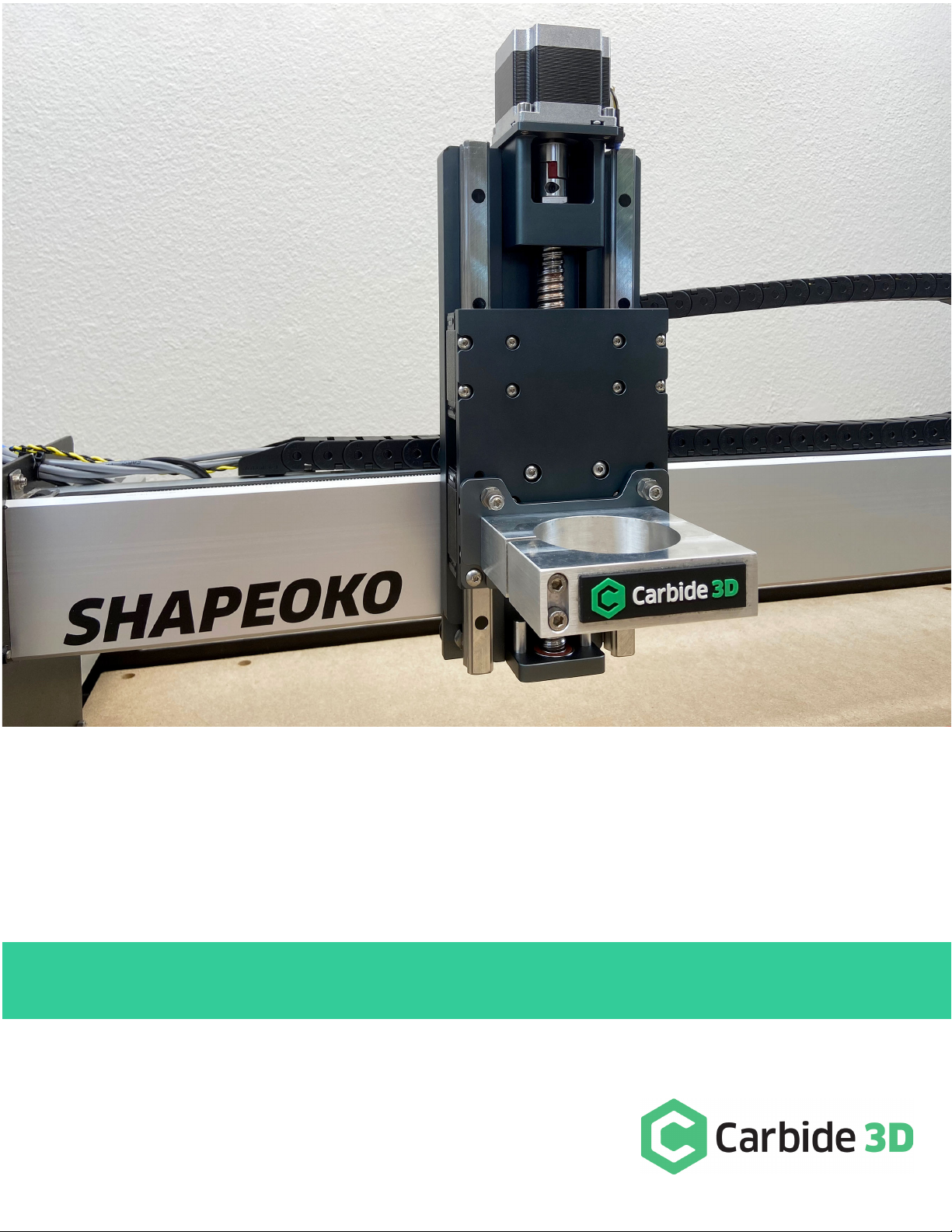
4. Label male/female ends of the white X- and Z-motor connectors behind the X/Z-carriage and disconnect.
a. Use a permanent marker or piece of tape to mark both male/female connectors.
WARNING: Do NOT disconnect motor connectors by pulling on the wires or by prying at the latch. Use pliers to
gently grip the base of each white connector and pull apart.
Remove the Homing Switches, Drag Chain, and V-Wheels
1. Label the X- and Z-Axis homing switches with a piece of tape (if needed).
2. Remove the Z-Axis homing switch from the front of the X/Z-carriage.
a. Use a 2.5mm hex key to remove the M3x12mm SHCS.
b.
CARRY OVER
the
Z-Axis homing switch
,
M3x12mm SHCS
, and
M3 washer
.
3. Remove the X-Axis homing switch plate (keep switch attached to plate) from the rear of the X/Z-carriage.
a. Use a 4mm hex key to remove the M5x35mm SHCS and 1-inch spacers.
b.
CARRY OVER
the
X-Axis homing switch assembly
,
M5x35mm SCHS
, and
1-inch
spacers
.
4. Remove L-shaped X-Axis drag chain bracket (keep drag chain attached to bracket) from rear of X/Z-carriage.
a. Use a 3mm hex key to remove the M5x10mm BHCS securing the L-bracket.
b.
CARRY OVER
the
bracket
and
M5x10mm BHCS
.
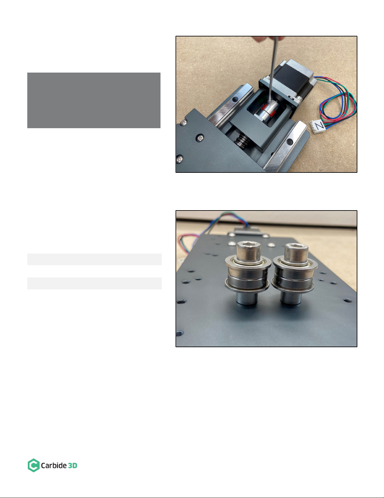
5.
Remove the lower two V-wheels of the X/Z-carriage.
a. Use a 3mm hex key and 8mm wrench to remove the lower two V-wheels.