2
Prima di dar inizio all’installazione leggere attentamente il presente fascicolo. In particolare, prendere visione dei dispositivi di
sicurezza previsti dal prodotto per utilizzarli con la massima efficacia. Prima di procedere con la programmazione leggere
attentamente le "NOTE" a pag. 10. L’utilizzo dei prodotti e la loro destinazione ad usi diversi da quelli previsti e/o consigliati,
non è stato sperimentato dal costruttore, pertanto i lavori eseguiti sono sotto la completa responsabilità dell’installatore.
Il presente manuale si rivolge a persone abilitate all'installazione di "APPARECCHI UTILIZZATORI DI ENERGIA ELETTRICA" e
richiede una buona conoscenza della tecnica, esercitata in forma professionale. Il costruttore declina ogni responsabilità per
eventuali danni provocati dalla mancata osservanza nell'installazione delle norme di sicurezza attualmente in vigore.
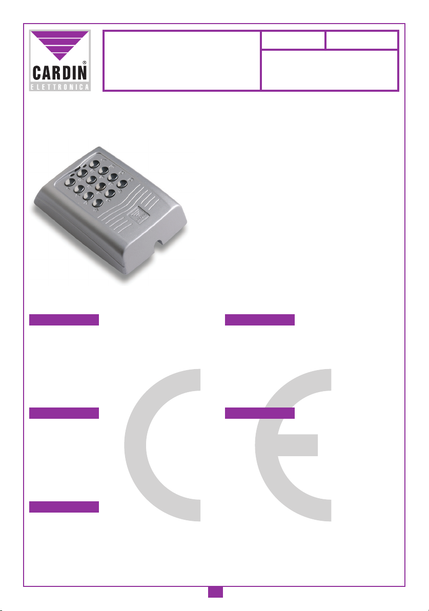
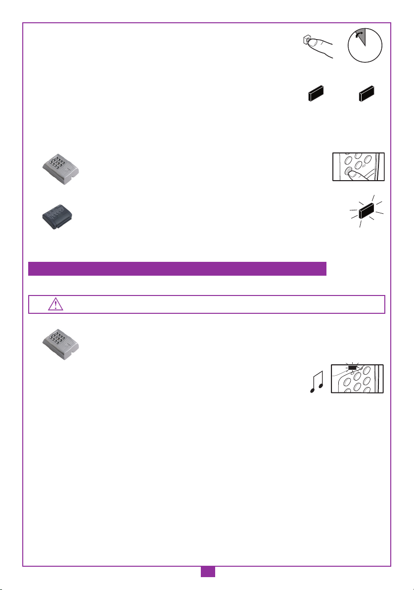
Descrizione
Il sistema si compone di due elementi collegati fra loro via filo:
- DKS250T tastiera numerica da esterno,
- DKS250R interfaccia per collegamento seriale.
La tastiera è costituita da una struttura metallica in zama, antiscasso, con verniciatura ad alta resistenza e tasti cromati
antiusura. Di facile installazione è dotata di un grado di protezione IP57 e di un sistema di fissaggio antiscasso con vite e
chiave speciali.
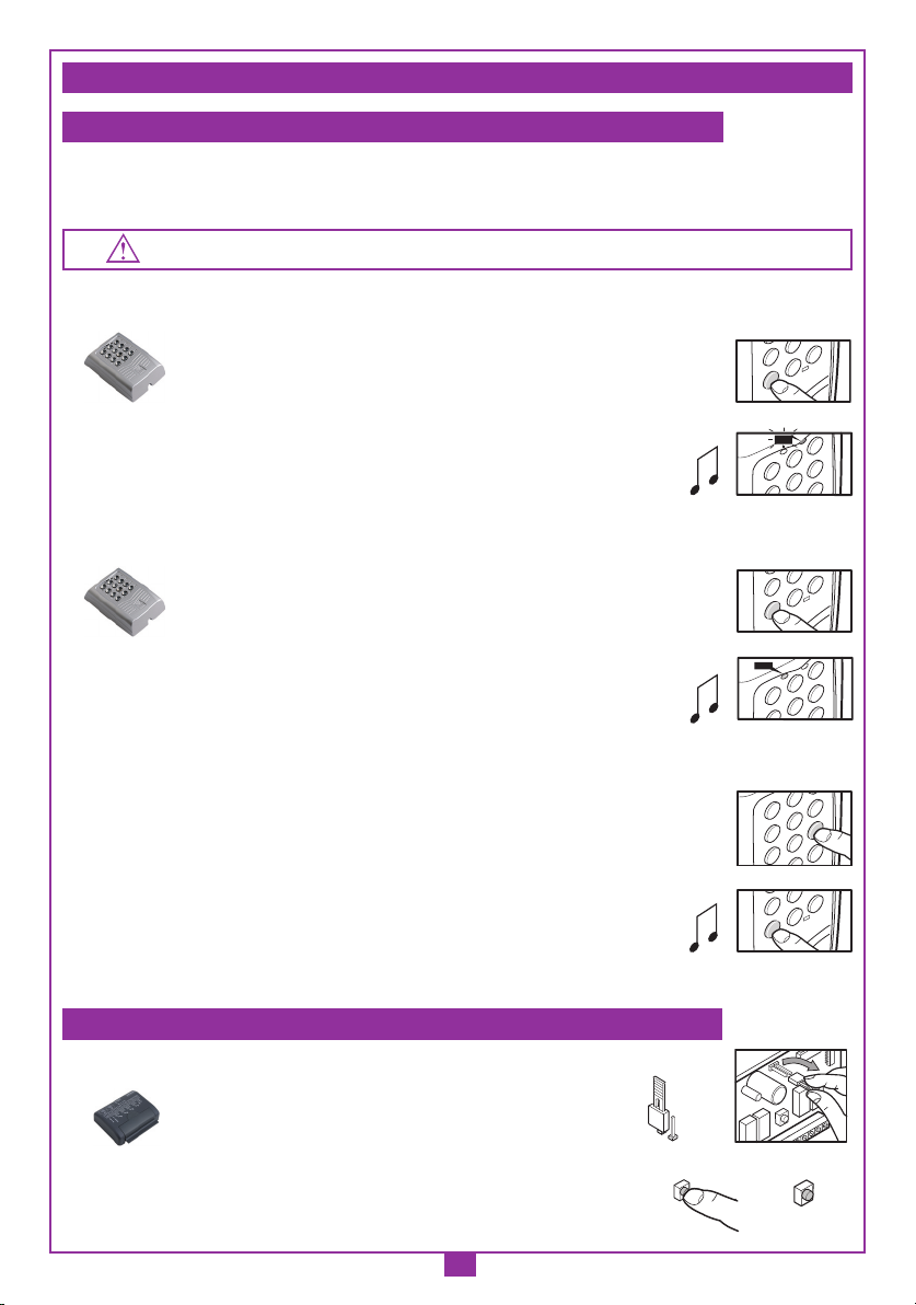
Dotata inoltre di:
- LED rosso segnalazione
- LED verde segnalazione
- 10 tasti numerici (0-9)
- un tasto di conferma *
- un tasto di annullamento operazione #
- 4 funzioni di canale (A, B, C, D)
- buzzer segnalazione sonora.
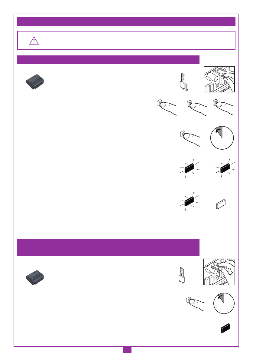
L’interfaccia collocata in un contenitore da interno IP20 si collega alla tastiera con cavo telefonico (o equivalente) a due
conduttori Ø 0,6 mm, lunghezza massima 150 m dotata di tasto di programmazione e due LED L1 verde L2 rosso di segna-
lazione visiva.
Possibilità di impiego
Il sistema DKS250 permette l'attuazione via filo di apparecchiature elettriche ed elettroniche, fornendo la massima sicurezza
e trovando il suo miglior impiego nel comando di porte e portoni motorizzati.
Numero di codici utente memorizzabili (max 6 cifre ciascuno) ............................................................................................... 250
Numero di combinazioni di codici disponibili ..................................................................................................................1 milione
CARATTERISTICHE TECNICHE
Alimentazione .............................................................................................12/24Vac-dc
Assorbimento:
Tastiera ................................................................................................................. 6mA
Interfaccia con tastiera ...................................................................................... 31mA
Interfaccia con tastiera e un canale attivo ........................................................ 54mA
Max potenza commutabile del relé con carico resistivo (escluse lampadine):
carico in ac/dc ............................................................................................60VA/24W
Tensione massima ....................................................................................... 30Vac-dc
Ritardo all'attivazione del relé .................................................................... 80-100ms
Temperatura di esercizio tastiera/interfaccia ...........................................-10° …+55°C
ITALIANO AVVERTENZE ITALIANO
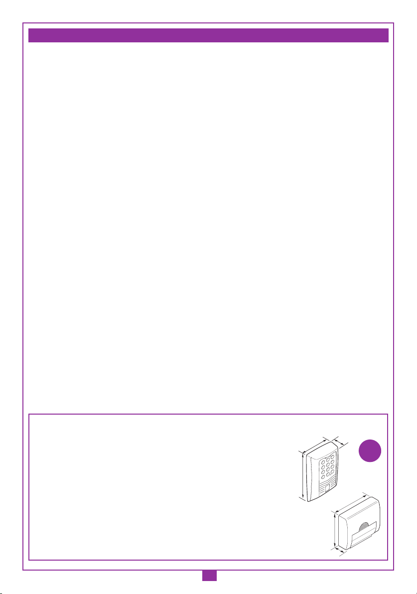
(dimensioni d'ingombro)
21-05-97
DM0275 Description :
Product Code :
Date :
Drawing number :
P.J.Heath
CARDIN ELETTRONICA S.p.A - 31020 San Vendemiano (TV) Italy - via Raffaello, 36 Tel: 0438/401818 Fax: 0438/401831
Draft :
All rights reserved. Unauthorised copying or use of the information contained in this document is punishable by law
RXRADO RXRADO
95
25
75
A
12
5
8
0
3
6
9
4
7
*
B
C
D
26
72
104
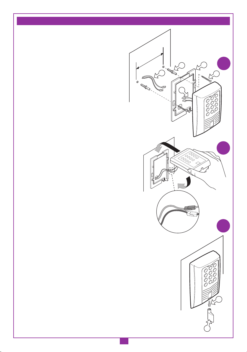
Montaggio Tastiera DKS250T a superfice
DKS250T
28-11-2001
DM0557 Description :
Product Code :
Date :
Drawing number :
P.J.Heath
CARDIN ELETTRONICA S.p.A - 31020 San Vendemiano (TV) Italy - via Raffaello, 36 Tel: 0438/401818 Fax: 0438/401831
Draft :
All rights reserved. Unauthorised copying or use of the information contained in this document is punishable by law
1
Dimensioni d'ingombro
Interfaccia
Tastiera