Cardin Elettronica PRG900 Series User manual

1
ZVL531.01 Mod: 13-09-2016
ITALIANO
ENGLISH
FRANÇAIS
DEUTSCH
ESPAÑOL
ATTENTION! Before installing this device read the
following instructions carefully!
Wiring diagram (installation example) Page 2
Important remarks Page 10
Electrical connection Pages 10-11
Programming procedure Page 12-13
Display mode Page 13
Remote control Page 14
Function modes Pages 14-15
Battery powered operation Page 15
Indications on the display Page 16
Technical specications Page 40
ATTENTION! Avant de commencer la pose, lire atten-
tivement les instructions!
Schéma électrique (exemple d’installation) Page 2
Consignes importantes Page 17
Branchement électrique Pages 17-18
Procédé de programmation Page 19-20
Menu de visualisation Page 20
Commande via radio Page 21
Modes de fonctionnement Pages 21-22
Fonctionnement à batterie Page 22
Indications de l’afcheur Page 23
Caractéristiques techniques Page 40
ACHTUNG! Bevor mit der Installation begonnen wird,
sollte die Anleitung aufmerksam gelesen werden.
Elektrischer Schaltplan (Anlagenart) Seite 2
Wichtige Hinweise Seite 24
Elektrischer Anschluss Seiten 24-25
Programmierverfahren Seite 26-27
Anzeigemenü Seite 27
Funkbefehl Seite 28
Betriebsmodus Seiten 28-29
Batteriebetrieb Seite 29
Displayanzeigen Seite 30
Technische Eigenschaften Seite 40
¡ATENCIÓN! Antes de iniciar la instalación del sistema,
leer atentamente las instrucciones.
Esquema eléctrico (instalación estándar) Página 8
Advertencias importantes Página 31
Conexionado eléctrico Páginas 31-32
Procedimiento de programación Página 33-34
Menú de visualización Página 34
Mando vía radio Página 35
Modalidad de funcionamiento Páginas 35-36
Funcionamiento por batería Página 36
Indicaciones en el display Página 37
Datos técnicas Página 40
ATTENZIONE! Prima di iniziare l'installazione leggere
le istruzioni attentamente!
Schema elettrico (impianto tipo) Pagina 2
Avvertenze importanti Pagina 3
Collegamento elettrico Pagine 3-4
Procedura di programmazione Pagina 5-6
Menu di visualizzazione Pagina 6
Comando via radio Pagina 7
Modalità di funzionamento Pagine 7
Funzionamento a batteria Pagina 8
Indicazioni del display Pagina 9
Caratteristiche tecniche Pagina 40
24 Vdc Motors
PROGRAMMATORE ELETTRONICO PER IL COMANDO DI PORTE E PORTONI MOTORIZZATI
ELECTRONIC PROGRAMMER CONTROLLING MOTORISED GATES AND DOORS
PROGRAMMATEURÉLECTRONIQUE POURLACOMMANDEDEPORTESETPORTAILSMOTORISÉS
ELEKTRONISCHERSTEUERUNGSEINHEIT FÜRDIE AUTOMATISIERUNGVON TÜRENUND TOREN
PROGRAMADOR ELECTRONICO PARA EL CONTROL DE LAS PUERTAS MOTORIZADAS
Questo prodotto è stato testato e collaudato nei laboratori della casa costruttrice, la quale ne ha verificato la
perfetta corrispondenza delle caratteristiche con quelle richieste dalla normativa vigente. This product has been
tried and tested in the manufacturer's laboratory who have verified that the product conforms in every aspect to
the safety standards in force. Ce produit a été testé et essayé dans les laboratoires du fabriquant. Pour l'installer
suivre attentivement les instructions fournies. Dieses Produkt wurde in den Werkstätten der Herstellerfirma
auf die perfekte Übereinstimmung ihrer Eigenschaften mit den von den geltenden Normen vorgeschriebenen
getestet und geprüft. Este producto ha sido probado y ensayado en los laboratorios del fabricante, que ha
comprobado la perfecta correspondencia de sus características con las contempladas
por la normativa vigente.
Model Date
Instruction manual Series
PRG900 V0.3
01-02-2013
ZVL531.01
CARDIN ELETTRONICA spa
Via del lavoro, 73 – Z.I. Cimavilla
31013 Codognè (TV) Italy
Tel: +39/0438.404011
Fax: +39/0438.401831
Http: www.cardin.it

2
Collegamenti scheda base
CC242ESSB
06-10-2011
DI0562 Description :
Product Code :
Date :
Drawing number :
P.J.Heath
CARDIN ELETTRONICA S.p.A - 31020 San Vendemiano (TV) Italy - via Raffaello, 36 Tel: 0438/401818 Fax: 0438/401831
Draft :
All rights reserved. Unauthorised copying or use of the information contained in this document is punishable by law
CENTRALINA 2 MOTORI CC CON ENCODER (V20)
(con 6 display a led + Jumper J6)
CHD
CHA
CHC
CHB
CHA CHD
CHC
CHB
B)
A)
24LC16
12
M2
RdBk
SEL
1
32
24V 12V 0
C
165432
NA
NC NC
C
NA
FTC-RX
132
24V
12V
0
FTC-TX
2
1
TB
2
1
LS
1
2
LP
2
CSP
CMN
CMN
FTCI (N.C)
TD (N.O)
CMN
TA (N.O)
TC (N.O)
TB (N.C)
LP
CTRL 24Vdc
OUT 24Vdc
7 8 9 10 11 12 13 14 15 16 17 18 19 20 21 22 23 24
LC/CH2
5 6
1 2
M1
CMN
ELS 12V
LS
TAL (N.O)
FTCS (N.C)
P1
J1
B1
CS 1435
DC 0535
3534
J4
R1
L9
L8
L6
L5
L10L7L4
P3
P2
L3
1 2 3 4 5 6 7 8 9
10 11 12 13 14
ON
DS1
123
J5
Pos.1 Pos.2
123
CSP (N.C)
L11
MM
D1
3 4
M2
Fuse F4A
Fuse F4A
F3
F1
25 26 27 28 29 30
CMN
FC1
FA1
FC2
FA2
CMN
CMN
Fuse F4A
F2
J3
BC
Fuse F10A
F4
J2
Fuse F10A
F5 L1
12
M1
RdBk
1
ANS400
J3
CSER
31 32 33
EMRG1
EMRG2
CMN
L2
SCHEMA ELETTRICO IMPIANTO TIPO - STANDARD WIRING DIAGRAM - SCHÉMA ÉLECTRIQUE DE L'EXEMPLE
D'INSTALLATION - ELEKTRISCHER SCHALTPLAN ANLAGENART - ESQUEMA ELÉCTRICO INSTALACIÓN ESTÁNDAR
1
CC242ESSBPRG900

3
• Il presente manuale si rivolge a persone abilitate all'installazione
di "apparecchi utilizzatori di energia elettrica" e richiede una
buonaconoscenzadellatecnica,esercitatainformaprofessionale
e della normativa vigente.
I materiali usati devono essere certicati e risultare idonei alle
condizioni ambientali di installazione.
• Questo prodotto è stato progettato e fabbricato in tutte le sue
parti a cura della Cardin Elettronica la quale ne ha vericato la
perfetta corrispondenza delle caratteristiche con quelle richieste
dalla normativa vigente.
• L'utilizzo dei prodotti e la loro destinazione ad usi diversi da quelli
previsti e/o consigliati, non è stata sperimentata dal costruttore,
pertanto i lavori eseguiti sono sotto la completa responsabilità
dell'installatore.
• Il programmatore qui descritto è dotato di un controllo sulla cor-
rente assorbita e deve essere destinato solo all'uso per il quale
è stato espressamente concepito: "Il comando e controllo di
motori Cardin in corrente continua".
• Il costruttore non risponde qualora l'impianto elettrico non risulti
conforme alle norme vigenti.
Attenzione! - Marcatura WEEE. Il simbolo indica che
il prodotto alla ne della propria vita utile deve essere
raccolto separatamente dagli altri riuti. L’utente dovrà
pertanto conferire l’apparecchiatura agli idonei centri
di raccolta differenziata dei riuti elettronici ed elettrici,
oppure riconsegnarla al rivenditore al momento dell’ac-
quisto di una nuova apparecchiatura di tipo equivalente,
in ragione di uno a uno.
L’adeguata raccolta differenziata per l’avvio al riciclaggio, al
trattamento e allo smaltimento ambientalmente compatibile
contribuisce ad evitare possibili effetti negativi sull’ambiente e
sulla salute e favorisce il riciclo dei materiali.
Lo smaltimento abusivo del prodotto da parte del detentore
comporta l’applicazione delle sanzioni amministrative previste
dalla normativa vigente nello Stato Comunitario di appartenenza.
Attenzione! Installare sempre la battuta di arresto mec-
canico delle ante.
Per il montaggio della scatola consultare il libretto d'istruzione
ZVL365.01 fornito con il programmatore elettronico.
Programmatore per motori in corrente continua con ricevente incor-
porata, che permette la memorizzazione di 300 codici utente.
La decodica è di tipo 'rolling code', e la frequenza di funzionamento
è 433 MHz con modulo radio S449 oppure 868 MHz con modulo
radio S486.
La velocità di rotazione dei motori è controllata elettronicamente, con
partenza lenta e successivo incremento; la velocità viene ridotta con
anticipo rispetto all'arrivo in battuta, in modo da ottenere un arresto
controllato.
La programmazione, eseguibile mediante un solo pulsante, permette
la regolazione del sensore di sforzo e della corsa totale della porta.
L'intervento del sensore antischiacciamento/anticonvogliamento
causa l'inversione del moto.
Attenzione! In nessun punto della scheda del programma-
tore è presente la tensione a 230 Vac: si ha solamente la
bassissima tensione di sicurezza.
Per la conformità alla normativa sulla sicurezza elettrica, è
proibito collegare i morsetti 7e 8direttamente ad un circuito
dove sia applicata una tensione superiore a 30 Vac/dc.
• Dopoaverinstallatoildispositivo, e primadidaretensione
alla centralina, vericare che il movimento del cancello
eseguito in modo manuale (con motore sbloccato) non
abbia punti di resistenza particolarmente marcata.
• L’uscita per l’alimentazione dei carichi controllati (mor-
setto 11) è pensata per ridurre il consumo della batteria in
assenza di tensione di rete; collegare pertanto le fotocellule
ed i dispositivi di sicurezza.
• Quando arriva un comando radio (o via lo) il programma-
tore dà tensione all’uscita CTRL 24 Vdc, e se le sicurezze
risultano a riposo attiva il motore.
• Laconnessione all’uscitaperi"carichicontrollati"permette
anche di eseguire l’autotest (abilitabile mediante i DIP 9 e
10) per la verica del corretto funzionamento dei dispositivi
di sicurezza.
• La presenza del sensore di corrente non elimina l’obbligo
di installare le fotocellule o altri dispositivi di sicurezza
previsti dalle normative vigenti.
• Accertarsi, prima di eseguire il collegamento elettrico, che
la tensione e la frequenza riportate sulla targhetta caratteris-
tiche corrispondano a quelle dell'impianto di alimentazione.
• Tra la centralina di comando e la rete deve essere inter-
posto un interruttore onnipolare, con distanza di apertura
tra i contatti di almeno 3 mm.
• Non utilizzare cavo con conduttori in alluminio; non stag-
nare l’estremità dei cavi da inserire in morsettiera; utilizzare
cavo con marcatura T min 85°C resistente agli agenti
atmosferici.
• I conduttori dovranno essere adeguatamente ssati in
prossimità della morsettiera in modo che tale ssaggio serri
sia l’isolamento che il conduttore (è sufciente una fascetta).
COLLEGAMENTI ALIMENTAZIONE CENTRALINA 230 Vac
• Collegare i li di comando e quelli provenienti
dalle sicurezze.
• Portare l'alimentazione generale al programma-
tore collegandolo alla morsettiera a due vie che
è già collegata al primario del trasformatore.
Nota: Qualora situazioni particolari richiedessero l'uso di un cavo più lungo
(cavo 100 m in bobina da tagliare secondo le esigenze dell'impianto) si ricorda
che, per evitare dispersione di corrente, la massima lunghezza consentita per
il cavo è 15 metri.
AVVERTENZE IMPORTANTI AVVERTENZE IMPORTANTI AVVERTENZE IMPORTANTI
LEGGERE ATTENTAMENTE LE SEGUENTI AVVERTENZE PRIMA DI PROCEDERE ALL’INSTALLAZIONE. PRES-
TARE PARTICOLARE ATTENZIONE A TUTTE LE SEGNALAZIONI DISPOSTE NEL TESTO. IL MANCATO
RISPETTO DI QUESTE POTREBBE COMPROMETTERE IL BUON FUNZIONAMENTO DEL SISTEMA E CREARE
SITUAZIONI DI PERICOLO GRAVE PER L'OPERATORE E GLI UTILIZZATORI DEL SISTEMA STESSO.
AVVERTENZE PER L'UTENTE
AVVERTENZE IMPORTANTI
N
L
PROGRAMMATORE ELETTRONICO

4
Collegamenti morsettiera
1- 2 M1 alimentazione motore 1
3- 4 M2 alimentazione motore 2
5 CMN comune per tutti gli ingressi/uscite
6 ELS uscita per elettroserratura (pilotata in continua) 12 Vdc – 15 W
7-8 LC-CH2 uscita (contatto puro, N.A.) per attivazione luce di cortesia (alimentata
a parte, Vmax = 30 Vac/dc: Imax = 1A) oppure per secondo canale radio. La
selezione viene fatta tramite jumper J5.
9 LS uscita lampada spia 24 Vdc 3W
10 LP uscita lampeggiante 24 Vdc 25 W con attivazione intermittente (50%), 12,5
Wcon attivazione ssa
11 Uscita carichi esterni controllati 24 Vdc(1)
12 CMN comune per tutti gli ingressi/uscite
13 CMN comune per tutti gli ingressi/uscite
14 Uscita carichi esterni 24 Vdc(1)
15 CMN comune per tutti gli ingressi/uscite
16 FC1 (N.C.) ingresso necorsa chiusura anta 1
17 FA1 (N.C.) ingresso necorsa apertura anta 1
18 FC2 (N.C.) ingresso necorsa chiusura anta 2
19 FA2 (N.C.) ingresso necorsa apertura anta 2
20 CMN comune per tutti gli ingressi/uscite
21 TAL (N.A.) ingresso pulsante di apertura limitata
22 TA (N.A.) ingresso pulsante di apertura
23 TC (N.A.) ingresso pulsante di chiusura
24 TD (N.A.) ingresso pulsante comando sequenziale
25 CMN comune per tutti gli ingressi/uscite
26 TB (N.C./8.2 kΩ) ingresso pulsante di blocco (all’apertura del contatto si
interrompe il ciclo di lavoro no ad un nuovo comando di moto) (2)
27 CSP (N.C./8.2 kΩ) ingresso per costa sensibile. L'apertura del contatto inverte
il moto sia nella fase di chiusura che nella fase di apertura (2)
28 FTCS (N.C./8.2 kΩ) ingresso per dispositivi di sicurezza (fotocellula di stop).
L'apertura del contatto blocca il moto; al ritorno nella condizione di riposo,
dopo il tempo di pausa il moto riprenderà in chiusura (solo con richiusura
automatica abilitata) (2)
29 FTCI(N.C./8.2 kΩ)ingresso perdispositivi di sicurezza (fotocellula diinversione
in chiusura). L’apertura del contatto, conseguente all’intervento dei dispositivi
di sicurezza, durante la fase di chiusura, attuerà l’inversione del moto (2)
30 CMN comune per tutti gli ingressi/uscite
31-32-33 Non collegati
34 Massa antenna ricevitore radio
35 Centrale antenna ricevitore radio (nel caso si utilizzi un’antenna esterna colle-
garla con cavo coassiale RG58 imp. 50Ω)
Nota (1) La somma delle due uscite per carichi esterni non deve superare 10W.
Nota (2) La selezione del tipo di contatto N.C./8.2 kΩ viene effettuata da menu visua-
lizzabile sul display a 6 cifre (parametro "SC")
TUTTI I CONTATTI N.C. NON UTILIZZATI VANNO PONTICELLATI e di conse-
guenza i test sulle sicurezze corrispondenti (FTCI, FTCS – DIP9 e DIP10) devono
essere disabilitati.
Se si vuole attivare il test sulle FTCI, FTCS sia la parte trasmittente che la parte rice-
vente di tale sicurezze vanno collegate ai carichi controllati (CTRL24Vdc). Si tenga
presente che nel caso sia abilitato il test, tra la ricezione del comando e il moto delle
ante/a passa circa 1 secondo.
Alimentare il circuito e vericare che lo stato dei LED di segnalazione sia come segue:
- L1 Alimentazione scheda acceso
- L2 Errata connessione batteria spento (3)
- L3 Programmazione codici trasmettitori spento
- L4 Segnalazione tasto blocco "TB" acceso (4)
- L5 Segnalazione fotocellule d'inversione "FTCI"acceso (4)
- L6 Segnalazione fotocellule di stop "FTCS"acceso (4)
- L7 Segnalazione costa sensibile "CSP"acceso (4)
- L8 Segnalazione tasto di apertura (TA) spento
- L9 Segnalazione tasto di chiusura (TC) spento
- L10 Segnalazione tasto di apertura limitata (TAL) spento
- L11 Segnalazione comando sequenziale (TD/CH1) spento
Nota (3) Nel caso sia acceso invertire immediatamente la connessione della
batteria (opzionale).
Nota (4) I LED sono accesi se la relativa sicurezza non è attivata. Vericare che
l'attivazione delle sicurezze porti allo spegnimento del LED ad esse
associato.
Nel caso in cui il LED verde di alimentazione "L1" non si accenda vericare
lo stato dei fusibili ed il collegamento del cavo di alimentazione al primario del
trasformatore.
Nel caso in cui uno o più LED di sicurezza non si accendano vericare che i
contatti delle sicurezze non utilizzate siano ponticellate sulla morsettiera.
Collegamenti scheda base
PRG900
04-02-2013
DC0535
CENTRALINA 2 MOTORI CC
(con 6 display a led - selezione a dipswitch )
Description :
Product Code :
Date :
Drawing number :
P.J.Heath
CARDIN ELETTRONICA S.p.A - 31020 San Vendemiano (TV) Italy - via Raffaello, 36 Tel: 0438/401818 Fax: 0438/401831
Draft :
All rights reserved. Unauthorised copying or use of the information contained in this document is punishable by law
CMN
CMN
FTCI (N.C)
TD (N.O)
CMN
TA (N.O)
TC (N.O)
TB (N.C)
LP
CTRL 24Vdc
OUT 24Vdc
7 8 9 10 11 12 13 14 15 16 17 18 19 20 21 22 23 24
LC/CH2
CSER
5 6
1 2
M1
CMN
ELS 12V
LS
TAL (N.O)
FTCS (N.C)
P1
J1
B1
CS 1435
DC 0535
3534
J4
R1
L9
L8
L6
L5
L10L7L4
P3
P2
L3
1 2 3 4 5 6 7 8 9
10 11 12 13 14
ON
DS1
123
J5
Pos.1 Pos.2
123
CSP (N.C)
L11
MM
D1
3 4
M2
Fuse F4A
Fuse F4A
F3
F1
25 26 27 28 29 30
31 32 33
EMRG1
EMRG2
CMN
CMN
FC1
FA1
FC2
FA2
CMN
CMN
Fuse F4A
F2
J3
BC
Fuse F10A
F4
J2
Fuse F10A
F5 L1
L2
B1 Buzzer segnalazione modalità "via radio"
D1 Display a LED a 6 cifre
DS1 Dip-switch di selezione
F1 Fusibile 4A (protezione circuito 24V)
F2 Fusibile 4A (protezione elettroserratura)
F3 Fusibile 4A (protezione circuito 24V modalità batteria)
F4 Fusibile 10A (protezione alimentazione motore)
F5 Fusibile 10A (protezione motore modalità batteria)
J1 Connessione batteria
J2 Connessione secondario trasformatore
J3 Jumper selezione canale radio
J4 Jumper abilitazione alla memorizzazione codici Tx via radio
J5 Jumper selezione morsetti 7, 8 (luce di cortesia/CH2 radio)
MM Modulo di memoria codici TX
P1 Tasto di programmazione (PROG)
P2 Tasto di memorizzazione codici TX (MEMO)
P3 Tasto di cancellazione codici TX (DEL)
R1 Modulo RF, 433 MHz per trasmettitore S449
2

5
ON
OFF
ON
OFF
ON
OFF
ON
OFF
ON
OFF
ON
OFF
ON
OFF
ON
OFF
PROCEDURA DI PROGRAMMAZIONE (Impostazioni del programmatore e del sensore di corrente)
Impostazione dip-switch DS1
ATTENZIONE: se si cambia l'impostazione dei dip, tale impostazione deve
essere memorizzata; premere dunque il tasto "PROG", sul display appare la
dicitura "dIP" segnalando l’avvenuta memorizzazione.
Selezione motori (DIP1)
"ON" = Funzionamento singolo motore
"OFF" = Funzionamento doppio motore
Selezione sfasamento (DIP2)
"ON" = Sfasamento in apertura abilitato
"OFF" = Sfasamento in apertura disabilitato
Se si abilita lo sfasamento, nella manovra di apertura prima parte l’anta 1 e poi
l’anta 2, mentre in chiusura prima parte anta 2 e poi anta 1. Con lo sfasamento
disabilitato le ante si mettano in moto contemporaneamente.
Comando sequenziale TD/CH1 (DIP3)
"ON" = Comando sequenziale "apre-chiude"
L’inversione del moto si ha solamente in fase di chiusura.
"OFF" = Comando sequenziale "apre-blocco-chiude-blocco"
Richiusura automatica (DIP 4)
"ON" = Richiusura automatica abilitata
"OFF" = Richiusura automatica disabilitata
Prelampeggio (DIP 5)
"ON" = Prelampeggio inserito
"OFF" = Prelampeggio escluso
Uscita lampeggiante (DIP 6)
"ON" = Uscita lampeggiante intermittente
"OFF" = Uscita lampeggiante ssa
Lampada spia (DIP 7)
"ON" = Lampada spia intermittente *
"OFF" = Lampada spia non intermittente
*Lalampada spia lampeggia lentamentedurantel’apertura,velocementedurante
la chiusura; resta accesa quando il cancello è bloccato non completamente
chiuso, ed è spenta quando il cancello è completamente chiuso.
Modalità FTCI (DIP 8)
"ON" = FTCI attive anche in blocco
Se le fotocellule risultano in allarme, ed il cancello è in stato di blocco, non viene
accettato nessun comando di moto (nemmeno di apertura).
"OFF" = FTCI attive solo in chiusura
In entrambi i casi l'attivazione della sicurezza FTCI
durante la fase di chiusura comporta l'inversione del moto.
Test su FTCI (DIP 9)
"ON" = Test su FTCI abilitato
"OFF" = Test su FTCI disabilitato
Se si abilita il test sulle sicurezze bisogna alimentare sia la parte trasmittente che
la parte ricevente ai carichi controllati (CTRL 24 Vdc). Con il test abilitato passa
circa un secondo dalla ricezione di un comando alla sua effettiva esecuzione.
Test su FTCS (DIP 10)
“ON” = Test su FTCS abilitato
“OFF” = Test su FTCS disabilitato
Se si abilita il test sulle sicurezze bisogna alimentare sia la parte trasmittente che
la parte ricevente ai carichi controllati (CTRL 24 Vdc). Con il test abilitato passa
circa un secondo dalla ricezione di un comando alla sua effettiva esecuzione.
Elettroserratura (DIP 11)
“ON” = Elettroserratura abilitata
“OFF” = Elettroserratura disabilitata
Abilitando l’elettroserratura, prima di iniziare il moto di anta 1 si attiva l’uscita ELS
(morsetto 6) e rimane attivata nché anta 1 non ha percorso qualche centimetro.
Fine corsa motore 1 (DIP 12)
“ON” = Fine corsa motore 1 abilitati
“OFF” = Fine corsa motore 1 disabilitati
Fine corsa motore 2 (DIP 13)
“ON” = Fine corsa motore 2 abilitati
“OFF” = Fine corsa motore 2 disabilitati
Dip 14 = Non utilizzato
ON
OFF
PARTE IL CONTEGGIO DEL
TEMPO DI PAUSA (MINIMO
2 SECONDI; MASSIMO 120
SECONDI), SEGNALATO DAL
LAMPEGGIO DEL SIMBOLO
"PAUSE" SUL DISPLAY.
PREMERE PROG
ATTENZIONE! SE UNA DELLE
ANTE DOVESSE MUOVERSI IN
CHIUSURA VUOL DIRE CHE LA
CONNESSIONE MOTORE NON
È CORRETTA, PERCIÒ
RIPREMERE PROG
ANNULLANDO LA PROCEDURA
DI PROGRAMMAZIONE,
INVERTIRE LA CONNESSIONE
MOTORE (CAVO ROSSO-NERO)
E RIPETERE LA
PROGRAMMAZIONE.
QUANDO LE ANTE ARRIVANO ALLA BATTUTA DI APERTURA, INVERTONO IL MOTO E DOPO
AVER PERCORSO QUALCHE CENTIMETRO RITORNANO IN APERTURA PER ACCERTARSI
DELLA POSIZIONE DELLA BATTUTA.
A QUESTO PUNTO LE ANTE, UNA ALLA VOLTA (PRIMA ANTA 2), VANNO IN CHIUSURA. QUANDO
UN’ANTA ARRIVA IN BATTUTA INVERTE IL MOTO PER QUALCHE CENTIMETRO PER POI
RITORNARE IN CHIUSURA, IN MODO DA STABILIRE LA CORRETTA POSIZIONE DELLA BATTUTA
DI CHIUSURA.
DOPO AVER EFFETTUATO QUESTE MANOVRE LA LOGICA DI CONTROLLO ESEGUE UNA
MANOVRA COMPLETA DI APERTURA E CHIUSURA IN MODO DA TARARE IL SENSORE DI
CORRENTE.
A CHIUSURA COMPLETATA IL
PROGRAMMATORE SALVA I PARAMETRI
ED ESCE DALLA PROGRAMMAZIONE.
L'OPERAZIONE NON È ANDATA
A BUON FINE. SARÀ
NECESSARIO RIPETERE LA
PROGRAMMAZIONE.
PREMERE IL TASTO PROG PER PIÙ
DI 4 SECONDI: COMPARE IL SIMBOLO
"PAUSE" CHE INDICA LA
PROGRAMMAZIONE DEL TEMPO DI PAUSA
1...4... sec.
PREMERE PROG
TERMINA IL CONTEGGIO DEL
TEMPO DI PAUSA E LE ANTE
ESEGUONO L’APERTURA
LENTAMENTE, IN MODO DA
TROVARE LO STATO DI
COMPLETAMENTE APERTO
• Èobbligatoria la presenza delle battute di apertura e chiusura per entrambe le ante.
• Accertarsi che le sicurezze siano a riposo e che la scheda sia alimentata da rete: in caso contrario non si entra in programmazione.
• Selezionare nel "menu di visualizzazione" (pagina 6) il modello del motoriduttore utilizzato.
SENSORE DI CORRENTE
Il programmatore esegue il controllo dell’assorbimento del motore, rilevando l’aumento
dello sforzo oltre i limiti consentiti nel normale funzionamento ed intervenendo come
sicurezza aggiuntiva. Se il sensore interviene durante la fase di chiusura, l'anta inverte
immediatamente il moto ed apre totalmente. Se il sensore interviene durante la fase
di apertura l'anta inverte immediatamente il moto di qualche centimetro e poi si ferma,
in modo da liberare l'ostacolo. Con la richiusura automatica abilitata l'anta richiude
dopo il tempo di pausa
Riposizionamento
Attenzione! Durante la manovra di riposizionamento il valore del sensore di corrente
“SnS" potrebbe essere alterato. Al termine della manovra torna automaticamente al
valore selezionato.
Se si dovesse vericare un blocco del programmatore dovuto ad un reset del program-
matore , allo sblocco di uno dei motori o ad un problema con uno dei
motori il lampeggiante e la lampada spia lampeggiano contemporaneamente
per 2 secondi e poi rimangono spenti per 10 secondi.
Se in questa fase si invia un comando (TA, TC, TAL o TD) al programmatore, il pro-
grammatore stesso porta automaticamente le ante a bassa velocità no alla battuta di
chiusura (per 2 volte come nella procedura di programmazione) in modo da recuperare
la posizione. A questo punto il programmatore riprende il normale funzionamento. (Se
viene dato un comando "TA" la procedura di recupero viene eseguita in apertura).
Durante la fase di riposizionamento non viene accettato nessun comando, mentre le
sicurezze agiscono bloccando il moto solamente nché risultano in allarme.
Per interrompere la fase di riposizionamento, premere il tasto "PROG" o "TB".
ON
OFF
ON
OFF
ON
OFF
ON
OFF

6
Sul display si accendono i segmenti relativi allo
stato dei comandi (acceso = comando attivo) e
delle sicurezze (acceso = sicurezza a riposo).
Il numero di manovre rimane sempre visualizza-
to, nché non si sceglie di cambiare l'imposta-
zione. Al superamento del numero 999999 la
cifra dei milioni è fornita dal numero di punti
decimali accesi.
10 sec
PREMERE PROG
10 sec
Lo stato delle sicurezze TB, FTCI, FTCS, CSP è
sempre rappresentato sul display.
Memorizzazione congurazione a DIP-SWITCH
e visualizzazione versione rmware (“03.”)
PREMERE
PROG
PREMERE
PROG
PREMERE
PROG
PREMERE PROG
PREMERE PROG
Dopo 10 secondi dall’ultima
modica il sistema esce
automaticamente salvando
il valore selezionato (es. 3)
10 sec
10 sec
Dopo 10 secondi dall’ultima
modica il sistema esce
automaticamente salvando
il valore selezionato (es. 3)
10 sec
10 sec
10 sec
Dopo 10 secondi dalla
ultima modica si uscirà
automaticamente salvando
il valore selezionato (es. 4)
10 sec
10 sec
PREMERE PROG
Ad ogni pressione del tasto viene
incrementato il numero (da 1 a 4).
PREMERE PROG
Ad ogni pressione del tasto viene
incrementato il numero (da 1 a 3).
PREMERE PROG
Ad ogni pressione del tasto
l’impostazione cambia.
APL = Impostazione spazio di apertura limitata (anta 1):
1 = 1/3 della corsa : 2 = metà della corsa
3 = 2/3 della corsa : 4 = corsa totale
SNS = Impostazione del sensore di corrente.
1 = assorbimento del motore + 2 ampère
2 = assorbimento del motore + 3 ampère
3 = assorbimento del motore + 3,5 ampère
Impostazione rallentamento
1 (Minimo) 2 - 3 - 4 - 5 (Massimo)
PREMERE PROG
Ad ogni pressione del tasto viene
incrementato il numero (da 1 a 3).
10 sec
Dopo 10 secondi dall’ultima
modica il sistema esce
automaticamente salvando
il valore selezionato (es. 3)
10 sec
Impostazione dello sfasamento tra le ante
1 = sfasamento minimo 3 = sfasamento massimo
2 = sfasamento medio
PREMERE PROG
Ad ogni pressione del tasto viene
incrementato il numero (da 1 a 3).
Nella modalità "test" (attivabile solo con motore fermo) è
possibile eseguire veriche sullo stato dei comandi e
sicurezze, ed effettuare eventuali manutenzioni.
Il lampeggiante si attiva una volta ad ogni comando
("TA-TC-TD-TAL-TB-FTCI-FTCS-CSP") ricevuto.
Per tornare al normale funzionamento premere "PROG",
facendo apparire la scritta "test", e attendere 10 secondi.
10 sec
Attivando gli ingressi ("TA-TC-TD-TAL-TB-
FTCI-FTCS-CSP") si aziona il lampeggiante.
10 sec
PREMERE PROG
Dopo 10 secondi dall’ultima
modica il sistema esce
automaticamente salvando
il valore selezionato
(es. Interrato)
PREMERE
PROG
PREMERE
PROG
PREMERE
PROG
Selezione del tipo di attuatore
BL2124 = pistone BLA24 = pistone
HL2524 = interrato
CUSTOM = Motore non Cardin
Selezione del contatto di sicurezza
0 1 2 3 4 5 6 7 8 9
TB N.C. N.C. N.C. N.C. N.C. N.C. N.C. N.C. 8.2 KΩ 8.2 KΩ
FTCS N.C. N.C. N.C. N.C. 8.2 KΩ 8.2 KΩ 8.2 KΩ 8.2 KΩ N.C. N.C.
FTCI N.C. N.C. 8.2 KΩ 8.2 KΩ N.C. N.C. 8.2 KΩ 8.2 KΩ N.C. N.C.
CSP N.C. 8.2 KΩ N.C. 8.2 KΩ N.C. 8.2 KΩ N.C. 8.2 KΩ N.C. 8.2 KΩ
Per i valore da A ad F vedere il paragrafo “selezione del contatto” a pagina 9
10 sec
10 sec
PREMERE PROG
Ad ogni pressione del tasto si modica
l’impostazione (tra 0 ... 9 - A ...F).
Dopo 10 secondi dalla
ultima modica si uscirà
automaticamente salvando
il valore selezionato (es. 5)
PMT = Impostazione della potenza del motore.
da livello 1 (2.5A) a livello 8 (6.0A)
PREMERE
PROG
10 sec
10 sec
Dopo 10 secondi dall’ultima
modica il sistema esce
automaticamente salvando
il valore selezionato (es. 3)
Parametri presenti solo per i motori CUSTOM
SPd= Livello di velocità in fase di rallentamento.
1 = velocità minima 3 = velocità massima
2 = velocità media
PREMERE
PROG
10 sec
10 sec
Dopo 10 secondi dall’ultima
modica il sistema esce
automaticamente salvando
il valore selezionato (es. 2)
MENU DI VISUALIZZAZIONE
Agendo sul tasto PROG si accede in sequenza alle seguenti funzioni:
- memorizzazione dello stato dei dip-switch;
- visualizzazione dello stato dei comandi e delle sicurezze;
- visualizzazione del numero di manovre;
- ingresso in modalità "test";
- impostazione dello spazio di apertura limitata;
- regolazione del sensore di corrente;
- selezione del tipo di motore;
- selezione contatto di sicurezza
(N.C./8.2 kΩ);
- impostazione tempo di rallentamento;
- impostazione tempo di sfasamento.

7
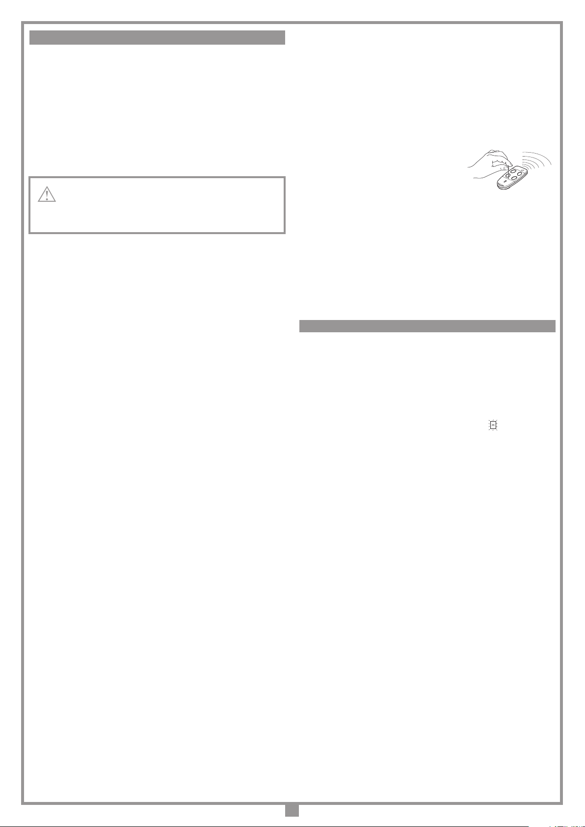
sia già stato memorizzato nel ricevitore, attivare il tasto all’interno del radio-
comando come indicato nella gura.
Nota:Tuttiiricevitori raggiungibilidall'emissionedelradiocomando,e cheabbiano
almeno un canale del trasmettitore memorizzato, attiveranno contemporanea-
mente il buzzer di segnalazione "B1".
3. Per selezionare il ricevitore in cui memorizzare il nuovo codice attivare uno
dei tasti di canale dello stesso trasmettitore. I ricevitori che non contengono il
codice di tale tasto si disattiveranno, con l'emissione di un "bip" lungo 5 secondi;
quello invece che contiene il codice emetterà un altro "bip" che dura un secondo,
entrando effettivamente nella modalità di memorizzazione "via radio".
4. Premere il tasto di canale precedentemente
scelto sul trasmettitore da memorizzare; ad
avvenutamemorizzazioneilricevitoreemetterà2
"bip" di mezzo secondo, dopodiché il ricevitore
sarà pronto a memorizzare un altro codice.
5. Per uscire dalla modalità lasciare trascorrere 3 sec. senza memorizzare codici.
Il ricevitore emetterà un "bip" lungo 5 sec. ed uscirà dalla modalità.
Nota: Quando la memoria viene completamente occupata, il buzzer emetterà 10
"bip"ravvicinati, uscendoautomaticamentedallamodalità dimemorizzazione"via
radio", ed il LED "L3" rimane acceso; la stessa segnalazione si ottiene anche ad
ognitentativodientrareinmodalità "viaradio"conmemoriainteramente occupata.
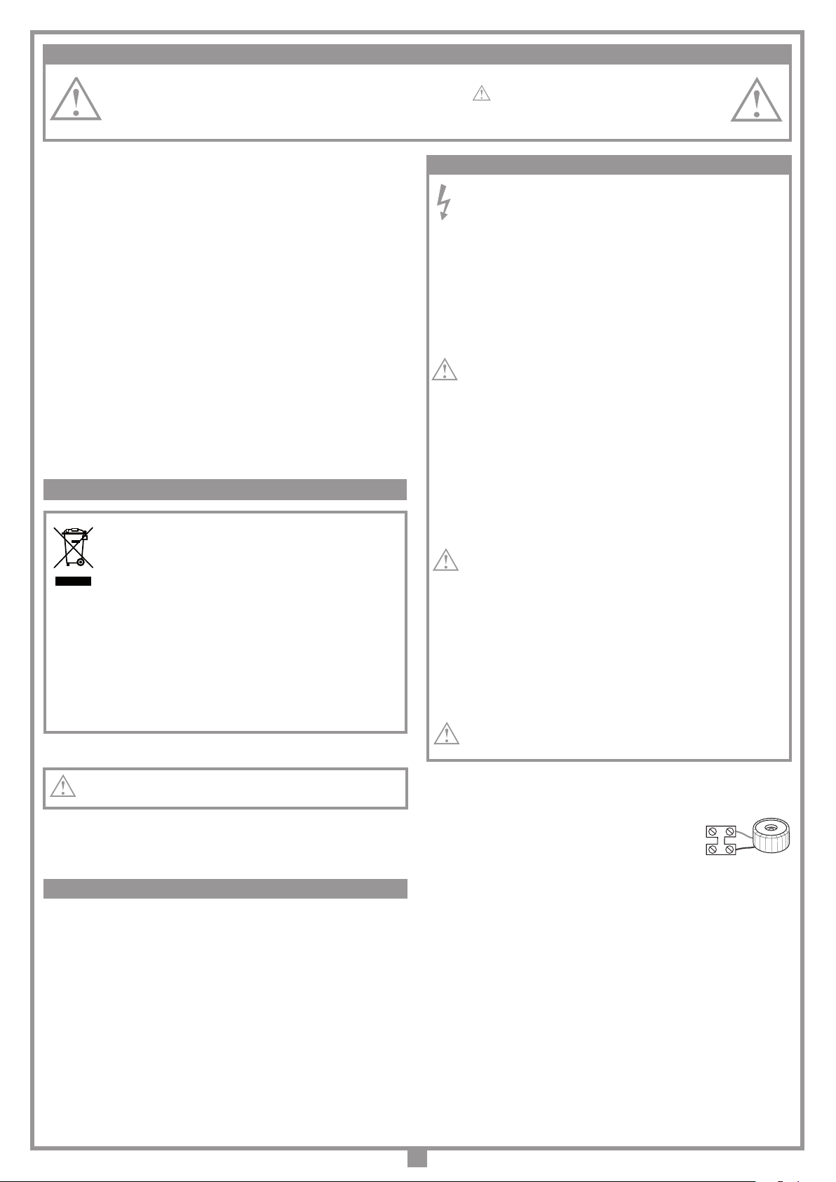
COLLEGAMENTO ANTENNA
Utilizzare l’antenna accordata ANS400, da collegare al ricevitore mediante
cavetto coassiale RG58 (impedenza 50Ω) di lunghezza max. 15 m.
1) Automatica
Si seleziona abilitando la richiusura automatica (dip "4" in posizione "ON"). Par-
tendo dalla condizione di completamente chiuso, il comando di apertura inizia
un ciclo completo di funzionamento, che terminerà con la richiusura automatica.
La richiusura automatica entra in funzione con un ritardo pari al tempo di pausa
programmato, a partire dal termine della manovra di apertura oppure dall'istante
in cui sono intervenute le fotocellule per l'ultima volta durante il tempo di pausa
(l'intervento delle fotocellule causa un reset del tempo di pausa).
Durante il tempo di pausa, sul display lampeggia il simbolo . La pressione del
tasto di blocco durante il tempo di pausa impedisce la richiusura automatica con
conseguente blocco del lampeggio sul display. La lampada spia rimane accesa
quando il portone non è completamente chiuso.
Nota: la luce di cortesia si accende ad ogni comando di movimento impartito al
sistema, sia via lo che via radio, e si spegne dopo 30 secondi dal termine della
manovra (solo se il jumper "J5" è in posizione 1, g .1).
2) Semi-automatica
Si seleziona disabilitando la richiusura automatica (dip "4" in posizione "OFF").
Il ciclo di lavoro è gestito con comandi separati di apertura e chiusura. Arrivato
in posizione di completa apertura il sistema attende un comando di chiusura
via radio o tramite tasto per completare il ciclo. La lampada spia rimane accesa
quando il cancello non è completamente chiuso.
3) Manovra manuale con motori sbloccati
Sbloccando i motori le ante possono essere spostate a mano.
APERTURA LIMITATA
Viene eseguita sempre su anta 1; lo spazio di apertura limitata può essere
impostato (vedi menu di visualizzazione) a 1/3, metà, 2/3 o corsa totale di anta 1.
Èpossibileeseguire ilcomando solocon leantecompletamentechiuse; se dip
"3"
èimpostato in “OFF” e durante l’aperturalimitata si attiva nuovamenteil comando
“TAL”, anta 1 si bloccherà, e ad un successivo comando andrà in chiusura. A
questo punto il comando non sarà più eseguito no alla completa chiusura.
LUCE DI CORTESIA / USCITA CH2 RADIO
I morsetti “7”,”8” fanno capo ai contatti C-NA di un relay; esso potrà essere
attivato come segue:
- jumper
J5
inposizione 1: il contattosichiudeinmodo temporizzato con la
modalità di “luce di cortesia”.
- jumper
J5
in posizione 2: il contatto viene pilotato dal secondo canale radio.
I morsetti “7”,”8” forniscono solamente un contatto puro, e non danno una tensi-
one all’esterno; questo signica che per usare la luce di cortesia sarà necessario
alimentare il circuito a parte, ed usare il contatto come semplice interruttore.
È possibile azionare a distanza l'automazione tramite radiocomando; per con-
gurare le due funzioni sui canali A-B-C-D si utilizzano i jumper di selezione "J3":
- nella posizione "A" si seleziona la funzione 1, COMANDO SEQUENZIALE;
- nella posizione "B" si seleziona la funzione 2, CH2 (morsetti 7, 8) solo se "J5"
è in posizione 2.
Ilcomandosequenziale ècongurabile(dip"3")in"apre-blocco-chiude-blocco"
oppure "apre-chiude".
Modulo di memoria (MM)
Estraibile, costituito da una memoria non volatile di tipo EEPROM, contiene i
codici dei trasmettitori e permette la memorizzazione di 300 codici. Nel modulo
di memoria i codici vengono mantenuti anche in assenza di alimentazione.
Primadi procedereallaprimamemorizzazione, ricordarsidicancellare
interamente la memoria.
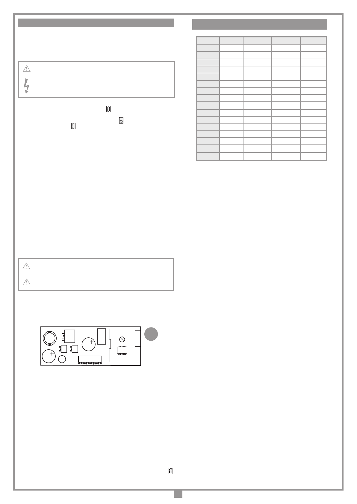
Dovendo sostituire la scheda elettronica per guasto, il modulo di
memoria può essere estratto da essa ed inserito nella nuova scheda
curandone l’orientamento come indicato in gura a pagina 2.
Segnalazioni LED "L3":
lampeggio veloce: cancellazione singolo codice
lampeggio lento: memorizzazione di un codice
sempre acceso: memoria interamente occupata.
GESTIONE DEI CODICI DEI TRASMETTITORI
Memorizzazione di un canale:
1. Premere il pulsante "P2" MEMO e tenerlo premuto: il LED "L3" lampeggia
lentamente.
2. Attivare contemporaneamente il trasmettitore sul canale da memorizzare.
3. Tenere premuto "P2" MEMO no a che il LED "L3" riprende a lampeggiare.
4. Rilasciare il tasto MEMO: il LED continua a lampeggiare.
5. Attivare una seconda volta il trasmettitore (stesso trasmettitore, stesso canale;
se il canale è diverso oppure si tratta di un altro trasmettitore la memorizzazione
termina senza successo).
6. Fine della memorizzazione: il LED "L3" rimane acceso per 2 secondi, segna-
lando la corretta memorizzazione.
Nota: Non è possibile memorizzare un codice che sia già in memoria: in un
caso simile durante l’attivazione del radiocomando (punto 2) si interrompe il
lampeggio del LED.
Solo dopo il rilascio del pulsante "P2" MEMO sarà possibile riprendere la pro-
cedura di memorizzazione. Se dopo la prima attivazione del radiocomando non
lo si attiva per la seconda volta, dopo 15 secondi si esce automaticamente dalla
modalità di memorizzazione senza memorizzare il nuovo codice utente.
Cancellazione di un canale:
1. Premere "P3" DEL e tenerlo premuto: il LED "L3" lampeggia velocemente.
2. Attivare il trasmettitore sul canale da cancellare.
3. Il LED rimane acceso per 2 secondi, segnalando l’avvenuta cancellazione.
Nota: Se l’utente che si vuole cancellare non è in memoria, il LED smette di
lampeggiare; sarà possibile riprendere la procedura di cancellazione solo dopo
il rilascio del pulsante "P3".
Sia per la procedura di memorizzazione che per quella di cancellazione, se si rilas-
cia il tasto prima dell’attivazione del radiocomando si esce subito dalla modalità.
Cancellazione completa della memoria utenti:
1. Tenere premuti entrambi i pulsanti ("P2+P3") per più di 4 secondi.
2. Il LED "L3" rimane acceso per tutto il tempo della cancellazione (8 secondi
circa).
3. Il LED "L3" si spegne: la cancellazione è stata completata.
Nota: Quando la memoria del ricevitore è prossima al completamento, la ricerca
dell’utente può durare un massimo di 1 secondo da quando è stato ricevuto il
comando radio. Se il LED "L3" è sempre acceso, la memoria è interamente
occupata: per memorizzare un nuovo TX sarà necessario cancellare un codice
dalla memoria.
Memorizzazione di ulteriori canali via radio
• La memorizzazione può essere anche attivata via radio (senza aprire la scatola
dove è alloggiata la centralina) se il jumper "J4" (g. 1) è inserito.
1. Assicurarsi che il jumper "J4" sia inserito.
2. Utilizzando un radiocomando, in cui almeno uno dei tasti di canale "A-B-C-D"
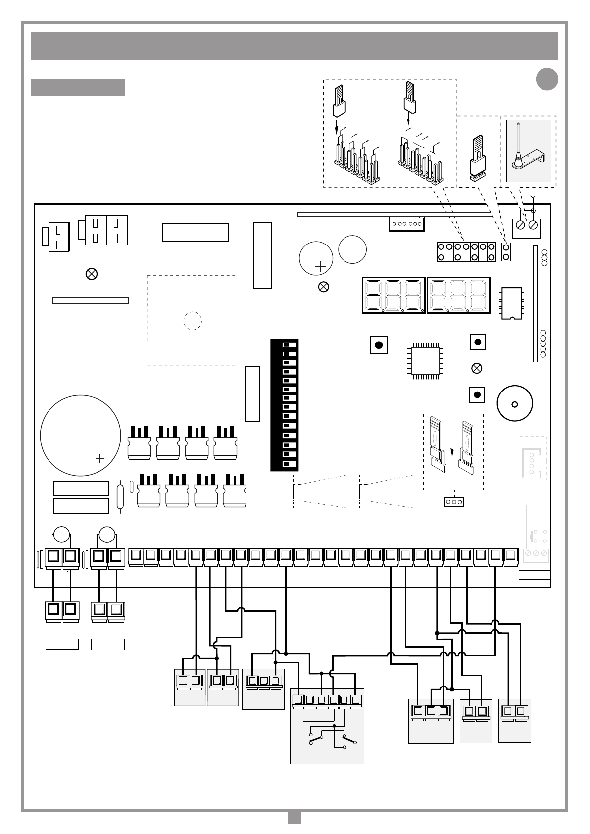
COMANDO VIA RADIO (figura 1 - pagina 2)
MEMORIZZAZIONE CODICE TX-RX
RCQ449100
13-04-2001
DM0531 Description :
Product Code :
Date :
Drawing number :
P.J.Heath
CARDIN ELETTRONICA S.p.A - 31020 San Vendemiano (TV) Italy - via Raffaello, 36 Tel: 0438/401818 Fax: 0438/401831
Draft :
All rights reserved. Unauthorised copying or use of the information contained in this document is punishable by law
MR
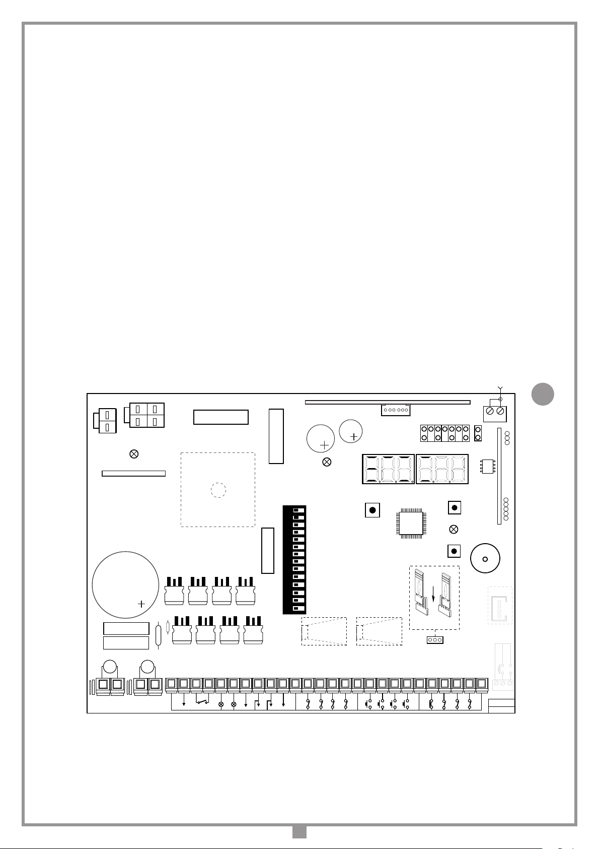
MODALITÀ DI FUNZIONAMENTO

8
Il dispositivo permette il funzionamento del gruppo propulsore anche in assenza
di rete.
• Il programmatore integra un circuito di carica per batterie NiMH a 24V gestito
da un microcontrollore dedicato, che regola la tensione in relazione allo stato
della batteria.
Per evitare il rischio di surriscaldamento utilizzare soltanto batterie
fornite dal costruttore (codice ricambio 999540).
Se la batteria presenta segni di danneggiamento va sostituita.
Le batterie devono essere installate e tolte da personale qualicato.
Le batterie esauste non devono essere gettate nei riuti urbani ma
smaltite secondo la direttiva WEEE.
• Per indicare il funzionamento a batteria, quando la porta è completamente
chiusa, sul display compare un trattino che scorre lungo il "perimetro
esterno". Se le batterie si scaricassero no alla soglia di guardia, sul display
si avrebbe ugualmente un trattino in movimento . Quando poi la batteria si
scarica troppo apparirà e si avrà il blocco completo del programmatore.
• Il ritorno al normale funzionamento si avrà al ripristino della tensione di rete;
per poter essere utilizzata nuovamente, la batteria dovrà ricaricarsi. Il tempo
di carica con batterie efcienti può arrivare ad un massimo di 12 ore. Se il
tempo richiesto è maggiore, valutare la sostituzione; si consiglia comunque,
per avere il massimo delle prestazioni, di sostituire le batterie ogni tre anni.
• Quando la porta è ferma, i carichi esterni controllati (CTRL 24 Vdc) non sono
alimentati, per aumentare l’autonomia delle batterie; quando viene inviato un
comando (via filo o via radio) il programmatore prima di tutto alimenta i carichi
e valuta lo stato delle sicurezze. Ne consegue che l’esecuzione del comando,
qualora consentita (sicurezze a riposo) verrà ritardata per il tempo necessario
alla ripresa del corretto funzionamento dei dispositivi stessi (circa 1 secondo).
Se dopo tale intervallo di tempo si rileva una sicurezza in allarme, il comando
non viene eseguito e l’alimentazione ai carichi esterni viene automaticamente
tolta: il programmatore torna in stato di stand-by.
Nota: per quanto detto sopra, se si desidera utilizzare un ricevitore esterno, lo
si dovrà alimentare collegandolo ai morsetti 13-14 (g. 1): soltanto così, infatti,
sarà possibile che il comando via radio riesca ad attivare il cancello.
• L'autonomia del sistema quando è alimentato a batteria è strettamente legata
alle condizioni ambientali, ed al carico connesso ai morsetti 13-14 (g. 1)
della centralina (che anche in caso di blackout alimentano i circuiti ad essa
collegati).
Quando le batterie si scaricano completamente (in assenza di tensione
di rete) il programmatore perde la posizione della porta e quindi, al
ripristino dell'alimentazione di rete si dovrà eseguire la procedura di
riposizionamento (vedi pag. 6). Evitare di lasciare il programmatore
disalimentato per periodi prolungati (oltre 2 giorni).
• In modalità batteria non è possibile entrare in programmazione.
• In assenza della tensione di rete, la tensione di batteria viene applicata alla
centralina, sia per quanto riguarda la parte logica che per quella di controllo
del motore.
Carica batteria ad innesto
LED di segnalazione
L2: risulta acceso quando la batteria non è collegata correttamente (g. 1);
LD: Segnala lo stato di funzionamento nel seguente modo (g. 3):
Spento: Batteria assente oppure centralina alimentata da batteria (in assenza
di rete). Durante i primi 20 secondi di funzionamento della centrale, dal
momento dell’accensione, il caricabatterie resta inibito e quindi non fornisce
nessuna segnalazione;
Lampeggi brevi: è stata rilevata una variazione di tensione sui morsetti della
batteria, come quando si connette o rimuove la batteria stessa;
Lampeggio singolo: si ripete ogni 2 secondi, indicando che la batteria è in
fase di carica di mantenimento;
Acceso: la batteria è in carica. Il tempo di carica può essere compreso tra
un minimo di 5 ore, ad un massimo di 12 ore.
Verifica delle batterie
Portare la porta in posizione di completa chiusura: il display risulta spento.
Vericare che il led "L2" (batterie sotto carica) sia spento.
Togliere l'alimentazione di rete, vericando che sul display appaia il simbolo .
Dare un comando di moto, e misurare la tensione complessiva delle due batterie
che dovrà essere di almeno 24 Vdc.
FUNZIONAMENTO A BATTERIA (OPZIONALE)
CS1256B
DC0536
LD
Scheda di innesto
PRG424BC
14-02-2013
DC0536 Description :
Product Code :
Date :
Drawing number :
P.J.Heath
CARDIN ELETTRONICA S.p.A - 31020 San Vendemiano (TV) Italy - via Raffaello, 36 Tel: 0438/401818 Fax: 0438/401831
Draft :
All rights reserved. Unauthorised copying or use of the information contained in this document is punishable by law
Scheda carica batteria
3
SC TB FTCS FTCI CSP
0 N.C. N.C. N.C. N.C.
1 N.C. N.C. N.C. 8.2 kΩ
2 N.C. N.C. 8.2 kΩN.C.
3 N.C. N.C. 8.2 kΩ8.2 kΩ
4 N.C. 8.2 kΩN.C. N.C.
5 N.C. 8.2 kΩN.C. 8.2 kΩ
6 N.C. 8.2 kΩ8.2 kΩN.C.
7 N.C. 8.2 kΩ8.2 kΩ8.2 kΩ
8 8.2 kΩN.C. N.C. N.C.
9 8.2 kΩN.C. N.C. 8.2 kΩ
A 8.2 kΩN.C. 8.2 kΩN.C.
B 8.2 kΩN.C. 8.2 kΩ8.2 kΩ
C 8.2 kΩ8.2 kΩN.C. N.C.
D 8.2 kΩ8.2 kΩN.C. 8.2 kΩ
E 8.2 kΩ8.2 kΩ8.2 kΩN.C.
F 8.2 kΩ8.2 kΩ8.2 kΩ8.2 kΩ
SELEZIONE DEL CONTATTO DI SICUREZZA

9
INDICAZIONI DEL DISPLAY (D1 - pagina 2)
Visualizzazioni all’accensione
Visualizzato per due secondi:
"PRG900" = modello della centralina
segnala la memorizzazione della
congurazione dei dip-switch e la
versione del rmware.
Segnalazioni di allarme
Sistema non programmato
È necessario entrare in modalità di programmazione per programmare il
sistema.
Fuori posizione
Nel caso di installazione, è necessario entrare in programmazione per pro-
grammare la corsa dell'anta.
Nel funzionamento normale invece segnala che verrà eseguita la procedura
di riposizionamento alla ricezione di un comando (TA, TC, TAL o TD vedi
pagina 6).
Blocco durante la programmazione tempi
Si verica quando viene attivato un contatto N.C. (FTCI, FTCS, CSP) durante
la programmazione tempi o riposizionamento. Una volta ristabilito lo stato
passivo delle sicurezze l'anta riprende il moto automaticamente.
Si verica anche quando viene a mancare la tensione di rete durante la fase
di programmazione.
Errore nel test delle sicurezze
Occorre controllare lo stato delle sicurezze, vericando che vadano in allarme
(LED relativo spento) quando un ostacolo si trova in mezzo al loro raggio
di azione. Se si riscontra un’anomalia sostituire la sicurezza guasta oppure
ponticellare l’ingresso relativo e disabilitare il test relativo alla sicurezza
stessa (dip 9 o 10).
Motore sbloccato (M1, M2)
Si verica quando si dà un comando di movimento ed uno dei 2 motori è
sbloccato. Bloccare il motore relativo (vedere le istruzioni relative al blocco
e sblocco del motore) e dare un comando: verrà eseguita la procedura di
riposizionamento
(pag. 5)
.
Segnalazioni di funzionamento
Programmazione del tempo di pausa
Programmazione automatica in corso
Fase di apertura
Blocco
Pausa per la richiusura automatica
(solo se abilitata)
Fase di chiusura
Aggiornamento del sensore di corrente anta 1
(in programmazione)
Aggiornamento del sensore di corrente anta 2
(in programmazione)
Aggiornamento di entrambi i sensori di corrente "anta
1 + anta 2" (in programmazione)
Apertura + compensazione sensore 1
Apertura + compensazione sensore 2
Chiusura + compensazione sensore 1
Chiusura + compensazione sensore 2
Modalità di test
Modalità batteria con batteria carica
Modalità batteria con batteria poco carica
Blocco per batteria scarica

10
Attention! There is no 230 Vac contact on any part of the
electronic card: only low voltage safety current is available.
In conformity with the electrical safety standards it is forbid-
den to connect binding posts 7and 8directly to a circuit that
receives power greater than 30 Vac/dc.
• After having installed the device, and before powering
up the programmer, release the door (manual release
mechanism) and move it manually, checking that it moves
smoothly and has no unusual points of resistance.
• The controlled load output (binding post 11) is aimed at
reducing battery power consumption (if they are installed)
duringblackouts; photocellsandother safetydevicesshould
be connected to this output.
• When a command is received, via radio or via wire, the
electronic programmer routes voltage to the CTRL 24 Vdc
output. It then evaluates the state of the safety devices and
if they are at rest it will activate the motor.
• Connecting devices to the controlled output contact also
allows you to carry out the autotest function (enabled
using DIPs 9 and 10) and check that the safety devices
are functioning correctly.
• The presence of the electrical current sensor does not
dispense with the obligation to install photoelectric cells
and other safety devices foreseen by the safety standards
in force.
• Before connecting the appliance make sure that the voltage
and frequency rated on the data plate conform to those of
the mains supply.
• Anallpole trip switch withatleast3 mmbetweenthecontacts
must be installed between the unit and the mains supply.
• Don't use cables with aluminium conductors; don't solder
the ends of cables which are to be inserted into the bind-
ing posts; use cables marked T min 85°C and resistant to
atmospheric agents.
• The terminal wires must be positioned in such a way that
both the wire and the insulating sheath are tightly fastened
(a plastic jubilee clip is sufcient).
POWER SUPPLY CONNECTION 230 Vac
• Connectthe controlandsecuritydevice wires.
• Run the mains power supply to the program-
mer and connect it to the separate two-way
terminal board that is already connected to
the transformer.
Note: If you need to choose a longer cable for particular installa-
tions (cut from the 100 metres of cable supplied in a reel) you must
remember that in order to avoid current dispersion the maximum
length of the cable must not exceed 15 metres.
• These instructions are aimed at professionally qualied "installers
of electrical equipment" and must respect the local standards
and regulations in force.
All materials used must be approved and must suit the environ-
ment in which the installation is situated.
• This product and all its relative components has been designed
and manufactured by Cardin Elettronica who have veried that
the product conforms in every aspect to the safety standards in
force.
• Any non authorised modications are to be considered improper
dangerous and the complete responsibility of the installer.
• This appliance is tted with a power input control system and
must be used exclusively for the purpose for which it has been
made "i.e. for the command and control of Cardin low voltage
motors".
• The manufacturer accepts no liability for situations arising from
the use of an electrical installation which does not conform to the
local standards and regulations in force.
Attention! Only for EU customers - WEEE marking.
This symbol indicates that once the products life-span
has expired it must be disposed of separately from
other rubbish. The user is therefore obliged to either
take the product to a suitable differential collection site
for electronic and electrical goods or to send it back to
the manufacturer if the intention is to replace it with a
new equivalent version of the same product.
Suitable differential collection, environmental friendly treatment
and disposal contributes to avoiding negative effects on the
ambient and consequently health as well as favouring the recy-
cling of materials. Illicitly disposing of this product by the owner
is punishable by law and will be dealt with according to the laws
and standards of the individual member nation.
Caution! mechanical stop anti-derailment buffers must
be installed.
To assembly the box read the instruction manual ZVL365.01 supplied
with the electronic programmer.
Electronic control unit for two dc motor with an incorporated radio
receiver card, which allows the memorisation of 300 user codes.
The decoder uses rolling codes and the reception frequency is
433.92 MHz with an S449 radio frequency module and 868 MHz
with an S486 radio frequency module,
The motor rotation speed is electronically controlled, starting slowly
and increasing in speed; the speed is reduced as it nears the travel
limit so as to enable a controlled smooth stop.
Programming is carried out using one button and allows you to set
the system, the current sensor and the entire gate travel distance.
The intervention of the anticrush/antidrag sensor during the closing
and opening stages causes travel direction inversion.
IMPORTANT REMARKS IMPORTANT REMARKS IMPORTANT REMARKS
READ THE FOLLOWING REMARKS CAREFULLY BEFORE PROCEEDING WITH THE INSTALLA-
TION. PAY PARTICULAR ATTENTION TO ALL THE PARAGRAPHS MARKED WITH THE SYMBOL
NOT READING THESE IMPORTANT INSTRUCTIONS COULD COMPROMISE THE CORRECT WORK-
ING ORDER OF THE SYSTEM AND CREATE DANGER SITUATIONS FOR THE USERS OF THE SYSTEM.
USER INSTRUCTIONS
IMPORTANT REMARKS
N
L
ELECTRONIC PROGRAMMER

11
Terminal board connections
1- 2 M1 power supply motor 1
3- 4 M2 power supply motor 2
5 CMN common for all inputs and outputs
6 ELS electric lock output (fed continuously) 12 Vdc - 15 W
7-8 LC-CH2 Potential free contact for the activation of the courtesy light (separate
power supply Vmax=30 Vac/dc: Imax=1A) or the second radio channel.
Selection is carried out using jumper "J5"
9 LS 24 Vdc 3 W output for an indicator light
10 LP 24 Vdc 25 W output for warning lights
intermittent activation (50%), 12,5 W continuous activation
11 24 Vdc controlled output, powering external loads (1)
12 CMN common for all inputs and outputs
13 CMN common for all inputs and outputs
14 24 Vdc output, powering external loads (1)
15 CMN common for all inputs and outputs
16 FC1 (N.C.) gate 1closing travel limit input
17 FA1 (N.C.) gate 1opening travel limit input
18 FC2 (N.C.) gate 2closing travel limit input
19 FA2 (N.C.) gate 2opening travel limit input
20 CMN common for all inputs and outputs
21 TAL (NO contact) limited opening button input
22 TA (NO contact) opening button input
23 TC (NO contact) closing button input
24 TD (NO contact) dynamic button input
25 CMN common for all inputs and outputs
26 TB
(N.C./8.2 kΩ)
stop button input (The opening of this contact interrupts the
cycle until a new movement command is given) (2)
27 CSP
(N.C./8.2 kΩ)
safety edge input. Opening this contact will provoke a travel
direction inversion during the closing stage and during the opening stage (2)
28 FTCS
(N.C./8.2 kΩ)
The opening of this contact will block all movement, until
the obstruction has been removed and the pause time has elapsed, due to
the safety device cutting in, the door will then continue moving in the closing
direction (only with automatic reclosing enabled) (2)
29 FTCI
(N.C./8.2 kΩ)
safety and control devices in input (photocells invert the
travel direction when an obstruction is detected). Opening this contact will
provoke a travel direction inversion during closure due to the cutting in of the
safety device (2)
30 CMN common for all inputs and outputs
31-32-33 Not connected
34 Outer conductor for radio receiver antenna.
35 Inner conductor for radio receiver antenna (if an external antenna is tted use
a coaxial type cable RG58 with an impedance of 50Ω).
Note (1) The total of the 2 external device outputs must not exceed 10 W.
Note (2) The selection of the type of contact (
N.C./8.2 kΩ) is carried out using parameter
"SC" on the six-gure display.
ALL UNUSED NC CONTACTS MUST BE JUMPED and consequently the security
device test must also be deactivated (FTCI , FTCS - Dip 9 and Dip 10 "OFF").
If you want to activate the FTCI, FTCS test both the transmission and receiver parts
of the security devices must be connected to the binding post marked "CTRL 24
Vdc". If the test is active there will be a 1 second delay between the command
transmission and movement of the gate/s.
Switch on the power and make sure that the indicator LEDs are in the following
condition.
- L1 Power on ON
- L2 Wrong battery connection OFF (3)
- L3 Transmitter code programming indicator OFF
- L4 Indicator for the blocking button "TB" ON
(4)
- L5 Indicator for the inverting photoelectric cells "FTCI" ON (4)
- L6 Indicator for the stop photoelectric cells "FTCS" ON (4)
- L7 Indicator for the safety edge "CSP" ON (4)
- L8 Indicator for the opening button "TA" OFF
- L9 Indicator for the opening button "TC" OFF
- L10 Indicator for the limited opening button "TAL" OFF
- L11 Indicator for the sequential command "TD/CH1" OFF
Note (3) If this LED is "ON" invert the battery power cables immediately.
Note (4) Check that the activation of the safety devices switches the corresponding
LEDs off.
If the green power on LED "L1" doesn't light up check the condition of the fuses
and the power cable connection at the transformer primary.
If one or more of the safety LEDs do not light up check the contacts of the
relative security devices and check that the unused safety device contacts have
been bridged.
B1 Signal buzzer "via radio" mode
D1 Six-segment LED display
DS1 Selection dip-switch
F1 4A fuse (24V circuit protection)
F2 4A fuse (electric lock protection)
F3 4A fuse (24V circuit protection during battery operation)
F4 10A fuse (motor power protection)
F5 10A fuse (motor protection during battery operation)
J1 Battery connection
J2 Transformer secondary protection
J3 Radio channel selection
J4 Enable transmitter memorisation via radio
J5 Binding posts
7, 8
selection (courtesy light/CH2 via radio)
MM Transmitter code memory module
P1 Programming button (PROG)
P2 Transmitter code memorization button (MEMO)
P3 Transmitter code cancellation button (DEL)
R1 Radio frequency module, 433 MHz for S449 transmitters
2
Collegamenti scheda base
PRG900
04-02-2013
DC0535
CENTRALINA 2 MOTORI CC
(con 6 display a led - selezione a dipswitch )
Description :
Product Code :
Date :
Drawing number :
P.J.Heath
CARDIN ELETTRONICA S.p.A - 31020 San Vendemiano (TV) Italy - via Raffaello, 36 Tel: 0438/401818 Fax: 0438/401831
Draft :
All rights reserved. Unauthorised copying or use of the information contained in this document is punishable by law
CMN
CMN
FTCI (N.C)
TD (N.O)
CMN
TA (N.O)
TC (N.O)
TB (N.C)
LP
CTRL 24Vdc
OUT 24Vdc
7 8 9 10 11 12 13 14 15 16 17 18 19 20 21 22 23 24
LC/CH2
CSER
5 6
1 2
M1
CMN
ELS 12V
LS
TAL (N.O)
FTCS (N.C)
P1
J1
B1
CS 1435
DC 0535
3534
J4
R1
L9
L8
L6
L5
L10L7L4
P3
P2
L3
1 2 3 4 5 6 7 8 9
10 11 12 13 14
ON
DS1
123
J5
Pos.1 Pos.2
123
CSP (N.C)
L11
MM
D1
3 4
M2
Fuse F4A
Fuse F4A
F3
F1
25 26 27 28 29 30
31 32 33
EMRG1
EMRG2
CMN
CMN
FC1
FA1
FC2
FA2
CMN
CMN
Fuse F4A
F2
J3
BC
Fuse F10A
F4
J2
Fuse F10A
F5 L1
L2

12
• The installation of both anti-derailment buffers is absolutely obligatory before starting programming.
• Make sure the safety devices are at rest and the ECU is receiving mains power otherwise you will not be able to enter programming.
• Choose the type of geared motor you are using from the "display menu" (page 13).
PROGRAMMING PROCEDURE (Setting the programmer and the current sensor)
Dip-switch settings DS1
CAUTION: If you change the dip settings you must memorise them; press the
"PROG" button, "dIP" will appear on the display indicating that the settings have
been memorised.
Motor selection (DIP1)
"ON" = Single motor operation
"OFF" = Double motor operation
Opening direction gate delay (DIP 2)
"ON" = Opening direction gate delay enabled
"OFF" = Opening direction gate delay disabled
Ifyouenable gate delaythefollowingwilloccur:during the openingmovementgate
leaf 1 moves rst and then gate leaf 2. In the closing direction gate leaf 2moves
rstthengate leaf 1. Ifgatedelayisdisabled both gate leavesmovesimultaneously.
Sequential command TD/CH1
(DIP3)
"ON" = Sequential command "open-close"
Travel direction inversion only during closing.
"OFF" = Sequential command "open-block-close-block"
Automatic reclosing (DIP4)
"ON" = Automatic reclosing enabled
"OFF" = Automatic reclosing disabled
Pre-flashing (DIP 5)
"ON" = Pre-ashing activated
"OFF" = Pre-ashing excluded
Warning light output (DIP 6)
"ON" = Warning light output intermittent
"
OFF" = Warning light output xed
Indicator light (DIP 7)
"ON" = Indicator light intermittent*
"OFF" = Indicator light xed
* The indicator light ashes slowly during opening, rapidly during closing; remains
lit when the gate is blocked but not completely closed and is off when the gate
is completely closed.
FTCI mode (DIP 8)
"ON" = FTCI also active when the gate is blocked
If the photocells are in alarm and the gate is blocked, no movement commands
will be accepted (even opening commands).
"OFF" = FTCI active only during closing
In both cases activating the FTCI safety device during the closing stage will force
travel direction inversion.
FTCI test (DIP 9)
"ON" = FTCI test enabled
"OFF" = FTCI test disabled
If you enable the security test you will have to connect both the transmitter and
the receiver to the controlled load output (CTRL 24 Vdc). When the test is enabled
one second will pass between receiving a command and carrying it out.
FTCS test (DIP 10)
"ON" = FTCS test enabled
"OFF" = FTCS test disabled
If you enable the security test you will have to connect both the transmitter and
the receiver to the controlled load output (CTRL 24 Vdc). When the test is enabled
one second will pass between receiving a command and carrying it out.
Electric lock (DIP 11)
"ON" = Electric lock enabled
"OFF" = Electric lock disabled
If the electric lock is enabled the ELS output (binding post 6) will be activated
before gate leaf 1 moves and will remain active until gate leaf one has moved a
few centimetres.
Travel limit motor 1 (DIP 12)
“ON” = Travel limit motor 1 enabled
“OFF” = Travel limit motor 1 disabled
Travel limit motor 2 (DIP 13)
“ON” = Travel limit motor 2 enabled
“OFF” = Travel limit motor 2 disabled
Dip 14 = Not used
WHEN THE GATES REACH THE COMPLETELY OPEN POSITION THEY INVERT THE TRAVEL
DIRECTION AND AFTER MOVING FOR A FEW CENTIMETRES THEY WILL OPEN AGAIN TO
CONFIRM THE COMPLETELY OPEN POSITION. AT THIS POINT THE LEAVES MOVE ONE AT A
TIME IN THE CLOSING DIRECTION (FIRST GATE LEAF 2). WHEN ONE OF THE GATE LEAVES
REACHES THE COMPLETELY CLOSED POSITION IT INVERTS THE TRAVEL DIRECTION AND
AFTER MOVING FOR A FEW CENTIMETRES IT WILL CLOSE AGAIN TO CONFIRM THE
COMPLETELY CLOSED POSITION.
AFTER HAVING CARRIED OUT THIS MANOEUVRE THE LOGIC CONTROL WILL OPEN THEN
CLOSE THE GATE LEAVES COMPLETELY IN ORDER TO CALIBRATE THE CURRENT SENSOR.
WHEN THE GATE REACHES THE
COMPLETELY CLOSED POSITION THE
PROGRAMMER SAVES THE PARAMETERS
AND QUITS THE PROGRAMMING MODE
THE OPERATION HAS NOT
SUCCEEDED. YOU WILL HAVE
TO REPEAT THE
PROGRAMMING PROCEDURE.
PRESS THE PROG BUTTON FOR MORE
THAN 4 SECONDS: THE "PAUSE" SYMBOL
WILL APPEAR INDICATING THAT YOU ARE
IN THE PAUSE PROGRAMMING MODE
1...4... sec.
PRESS PROG
THE PAUSE TIME COUNT
ENDS AND THE DOOR OPENS
SLOWLY IN ORDER TO FIND
THE COMPLETELY OPEN
POSITION.
THE PAUSE TIME COUNT
WILL START (MIN. 2
SECONDS: MAX 120
SECONDS) INDICATED BY
THE "PAUSE" SYMBOL
FLASHING ON THE DISPLAY
PRESS PROG
ATTENTION! IF THE GATE MOVES
IN THE CLOSING DIRECTION THE
MOTOR CONNECTION IS
INCORRECT. PRESS “PROG”
AGAIN TO CANCEL THE
PROGRAMMING PROCEDURE,
INVERT THE MOTOR
CONNECTION (RED AND BLACK
CABLE) AND REPEAT THE
PROGRAMMING PROCEDURE.
CURRENT SENSOR
The programmer checks the electrical input to the motor, detecting any eventual
increase in effort above the normal operating limits and intervenes as an additional
safety device. If the sensor intervenes during the opening direction the gate inverts
the travel direction immediately and proceeds to the fully open position. If the
sensor intervenes during the closing direction the gate automatically inverts the
travel direction of a few centimetres and then stops to free the obstacle.
Repositioning
Attention! During the repositioning manoeuvre the current sensor value “SnS"
could be different leading to a momentary increase in the door impact force. At
the end of the manoeuvre, however, it will reset automatically to the chosen value.
If a prooblem occurs after a programmer reset , when one of the motors has
been released or there is a problem with one of the motors the
warning lights and indicator light will ash simultaneously for 2 seconds and will
then switch off for 10 seconds.
If in this stage you send a (TA, TC, TAL or TD) command to the programmer.
The programmer will move the gates slowly to the completely closed position (2
times as in the programming procedure) in order to recover the correct position.
At this point the programmer will function normally. If a “TA" command is given
the positioning recovery is carried out in the opening direction.
No commands will be accepted during repositioning but the security devices will
cut
in and block all movement if they go into alarm.
To interrupt the repositioning manoeuvre press the “PROG" or “TB" button.
ON
OFF
ON
OFF
ON
OFF
ON
OFF
ON
OFF
ON
OFF
ON
OFF
ON
OFF
ON
OFF
ON
OFF
ON
OFF
ON
OFF
ON
OFF

13
DISPLAY MENU
The segments regarding the command status
(LED “ON” = command active) and safety status
(LED “ON” = safety device at rest) light up.
The number of manoeuvres appears on the display.
This number always remains visible until you
change the setting. Once 999999 has been
exceeded the lighting up of the decimal point on
the display equals 1 million + the six gure number.
10 sec
PRESS PROG
10 sec
The status of the security devices TB, FTCI, FTCS
and CSP are always shown on the display
.
Memorising the DIP-SWITCH settings and displaying
the rmware version (“03.”)
PRESS
PROG
PRESS
PROG
PRESS
PROG
PRESS PROG
PRESS PROG
10 sec
10 s after the last
modication you will
automatically exit the mode
and the selected values will
be saved (eg. 4)
10 s after the last
modication you will
automatically exit the mode
and the selected values will
be saved (eg. 3)
10 sec
10 sec
PRESS PROG
Each time the button is pressed the
number increases (from 1 to 4).
APL = Setting the limited opening space (gate1):
1 = 1/3 of the distance : 2 = half the distance
3 = 2/3 of the distance : 4 = the entire distance
SNS = Setting the current sensor.
1 = motor consumption + 2 amps
2 = motor consumption + 3 amps
3 = motor consumption + 3,5 amps
In the "test" mode (activated when the motor has
stopped) it is possible to check the status of the
command and safety devices.
The warning lights will activate once, each time a
“TA-TC-TAL-TD-TB-FTCI-FTCS-CSP” command is
received. To return to the normal mode press the button
again “test” will appear, then wait for 10 seconds.
10 sec
10 sec
PRESS PROG
When the ("TA-TC-TD-TAL-TB- FTCI-FTCS-CSP")
inputs are activated the warning lights will light up.
PRESS PROG
Each time the button is pressed the
number increases (from 1 to 3).
10 sec
10 s after the last
modication you will
automatically exit the mode
and the selected values will
be saved
(eg. 3)
10 sec
10 sec
10 sec
PRESS PROG
Each time the button is pressed
the setting changes.
Deceleration settings
1 (Minimum) 2 - 3 - 4 - 5 (Maximum)
PRESS PROG
Each time the button is pressed
the number increases (from 1 to 3)
.
10 sec
10 s after the last
modication you will
automatically exit the mode
and the selected values will
be saved
(eg. 3)
10 sec
Setting the delay between the gates
1 = minimum gate delay 3 = maximum gate delay
2 = medium gate delay
PRESS PROG
Each time the button is pressed the
number increases (from 1 to 3)
.
10 s after the last modication
you will automatically exit the
mode and the selected values
will be saved
(
eg.
underground)
PRESS
PROG
PRESS
PROG
PRESS
PROG
Selecting the type of motor
BL2124 = operator arm BLA24 = operator arm
HL2524 = underground operator
CUSTOM = third part motor
Selecting the type of security contact
0 1 2 3 4 5 6 7 8 9
TB N.C. N.C. N.C. N.C. N.C. N.C. N.C. N.C. 8.2 KΩ 8.2 KΩ
FTCS N.C. N.C. N.C. N.C. 8.2 KΩ 8.2 KΩ 8.2 KΩ 8.2 KΩ N.C. N.C.
FTCI N.C. N.C. 8.2 KΩ 8.2 KΩ N.C. N.C. 8.2 KΩ 8.2 KΩ N.C. N.C.
CSP N.C. 8.2 KΩ N.C. 8.2 KΩ N.C. 8.2 KΩ N.C. 8.2 KΩ N.C. 8.2 KΩ
For the values from A to F see the paragraph “contact selection” on page 16
10 sec
10 sec
PRESS PROG
Each time the button is
pressed the setting changes
(from 0 ... 9 - A ...F).
10 s after the last
modication you will
automatically exit the mode
and the selected values will
be saved
(
eg.
5)
PMT = Motor power setting.
from level 1 (2.5A) to level 8 (6.0A)
PRESS
PROG
10 sec
10 sec
10 s after the last modication
you will automatically exit the
mode and the selected values
will be saved (eg. 3)
Parameters only present in CUSTOM motors
SPd= Speed level during deceleration.
1 = minimum speed 3 = maximum speed
2 = medium speed
PRESS
PROG
10 sec
10 sec
10 s after the last modication
you will automatically exit the
mode and the selected values
will be saved (eg. 2)
Using the PROG button you can access the following functions in sequence:
- memorising the status of the dip-switches;
- display the status of the command and safety devices;
- display the number of manoeuvres;
- access the "test" mode;
- set the limited opening distance;
- set the current sensor level;
- selecting the type of motor;
- selecting the security contact
(N.C./8.2 kΩ);
- setting the deceleration time;
- setting the gate delay time.

14
The system can be remotely activated using radio control devices; to set the
two functions to channels A-B-C-D use the selection jumper “J3”:
- in position “A” function 1 is selected, SEQUENTIAL COMMAND;
- in position “B” function 2 is selected, CH2 (binding posts 8, 9) only if "J5"
is in position 2.
The sequential command may be set (dip “3”) to “open-block-close-block”
or “open-close”.
Memory module (MM)
This is extractable, furnished with a non volatile EEPROM type memory and
contains the transmitter codes and allows you to memorise up to 300 codes.
The programmed codesare maintained inthis module even duringblackouts.
Before memorising the transmitters for the rst time remember
to cancel the entire memory content. If the electronic card has
to be replaced due to failure, the module can be extracted from
it and inserted into the new card. Make sure that the module is
correctly inserted as shown on page 2.
Signal LED "L3":
Flashing quickly: cancels a single code
Flashing slowly: memorises a single code
Permanently lit: memory full.
TRANSMITTER CODE MANAGEMENT
Memorising a channel:
1. Press and hold down button "P2" MEMO: The LED "L3" will ash slowly.
2. At the same time activate the transmitter which is to be memorised.
3. Hold down button "P2" MEMO until LED "L3" starts to ash again.
4. Release the MEMO button: The LED will continue to ash.
5. Activate the transmitter again (same transmitter, same channel; if the
channel is different or it is a different transmitter the memorisation attempt
will abort without success).
6. End of memorisation: the LED "L3" will remain lit for 2 seconds, indicating
that the transmitter has been correctly memorised.
Notes: It is not possible to memorise a code which is already in memory: if
you attempt this, the LED will switch off when you activate the transmitter
(point 2). Only after releasing the button "P2" MEMO will you be able to
continue the memorising procedure.
If after activating the transmitter for the rst time you wait for more than fteen
seconds without activating the transmitter a second time the memorisation
attempt will abort without success.
Cancelling a channel:
1. Press and hold down the button "P3" DEL: the LED "L3" will ash quickly.
2. Activate the transmitter channel that is to be cancelled.
3. The LED will remain lit for 2 seconds, indicating that the transmitter has
been cancelled.
Notes: If the user that you wish to cancel is not in memory, the LED will stop
ashing; only after releasing the button "P3" will you be able to continue the
cancellation procedure.
For both the memorisation and cancellation procedures, if the button is
released before activating the transmitter the procedure will abort.
Cancelling all user codes from memory:
1. Keep both buttons pressed down ("P2+P3") for more than four seconds.
2. LED"L3"will remainlit during theentirecancellationtime(about8seconds).
3. LED "L3" switches off when the cancellation procedure has terminated.
Note: When the memory is almost full the time required to search for a user
code could take up to 1 second from when the command was received.
If LED "L3" remains lit memory is completely full. To memorise a new trans-
mitter you will rst have to cancel a code from memory.
Memorising ulterior channels via radio
• Memorisation can be activated by radio (without opening the receiver
container) if jumper "J4" has been inserted (g. 1).
1. Make sure that the jumper "J4" has been inserted.
2. Using a transmitter, in which at least one channel button "A, B, C or D" has
already been memorised in the receiver, press the button in the transmitter
as shown in gure.
Note: all the receivers within range when the channel button is pressed (and
which have at least one of the transmitter channel buttons memorised) will
activate their signal buzzer "B1" (g. 1).
3. Press one of the channel buttons on the same transmitter. The receivers
which do not contain that channel code will sound a ve-second long
"beep" and will then deactivate. The receivers which contain the channel
code will sound a one-second long "beep" and will enter the "program-
ming via radio" mode.
4. Press the previously chosen channel but-
tons on the transmitter which you wish to
memorise; the receiver will sound 2 "beeps"
ofhalfa second eachafterwhichthereceiver
will be ready to receive another code.
5. To leave the programming mode wait for
3 seconds without pressing any buttons. The receiver will sound a ve-
second long "beep" and will then exit the programming mode.
Note: When the memory is entirely occupied the buzzer will sound 10 rapid
"beeps" and will automatically leave the "programming via radio" mode.
LED "L3" will remain lit on the receiver.
The same signal is given each time you try to enter "programming via radio"
when the memory is full.
CONNECTING THE ANTENNA
Connect an ANS400 tuned antenna using a coaxial cable RG58 (impedance
50Ω) with a maximum length of 15 m.
1) Automatic
Selected by enabling automatic reclosing (dip "4" in position "ON"). When
the door is completely closed the opening command will start a complete
cycle which will end with automatic reclosing.
Automatic reclosing starts after the programmed pause period has elapsed
when the opening cycle has been completed or straight away after the
intervention of a photoelectric cell (the intervention of a photoelectric cell
causes the pause time to be reset).
During the pause time the symbol will ash on the display and pressing
the blocking button during this period will stop automatic reclosing and
consequently stop the display from ashing.
The indicator light remains lit until the closing manoeuvre has terminated.
Note: the courtesy light switches on each time a movement command is
given (both via cable or via radio) and switches off 30 seconds after the
manoeuvre has been completed
(only if jumper "J5" is in position "1", g. 1)
.
2) Semiautomatic
Selected by deactivating automatic reclosing (dip "4" in position "OFF").
Work cycle control using separate opening and closing commands. When
the door has reached the completely open position the system will wait until
it receives a closing command either via an external control button or via
radio control, before completing the cycle.
The indicator light remains lit until the closing manoeuvre has terminated.
3) Manual manoeuvring with released motors
Releasing the motor the gate can be moved by hand.
LIMITED OPENING
This always effects gate 1; the limited opening space can be set (see display
menu) to 1/3, half, 2/3 or the entire opening distance for gate 1.
The command can only be carried out with both gates completely closed; if
dip
"3"
is set to “OFF” and during opening you activate the “TAL” command
again gate leaf 1 will block and when it receives the next command it will move
in the closing direction.
At this point the command cannot be used again until complete closure.
COURTESY LIGHT /CH2 RADIO OUTPUT
Bindingposts “7”,“8”arelinkedto aC-NOrelay;this canbeactivatedasfollows:
- jumper J5 in position 1: the contact is closed by a timer and works as a
“courtesy light”
- jumper J5 in position 2: the contact works as a second radio channel.
Binding posts “7”,”8” only give a potential free contact; this means that the
courtesy light will have to be powered by an external circuit and the contact
used as a simple switch.
REMOTE CONTROL (fig. 1 - page 2)
MEMORIZZAZIONE CODICE TX-RX
RCQ449100
13-04-2001
DM0531 Description :
Product Code :
Date :
Drawing number :
P.J.Heath
CARDIN ELETTRONICA S.p.A - 31020 San Vendemiano (TV) Italy - via Raffaello, 36 Tel: 0438/401818 Fax: 0438/401831
Draft :
All rights reserved. Unauthorised copying or use of the information contained in this document is punishable by law
MR
FUNCTION MODES

15
This device allows the propulsion unit to work during blackouts.
• The programmer has a built in charger for NiMH 24V batteries that is
managed by a dedicated micro controller. The control chip adjusts the
voltage according to the condition of the batteries.
To avoid the risk of overheating only use batteries supplied by
the manufacturer SPN 999540.
If the batteries show signs of damage they must be replaced
immediately.
The batteries must only be installed/removed by qualied
personnel. Used batteries must not be thrown into domestic
rubbish bins and they must be disposed of according to the
WEEE standards and regulations in force.
• To indicate that the programmer is working off battery power when the
door is completely closed a hyphen owing around the perimeter of
the display will appear.
If the battery is under charged a hyphen owing around the lower half
of the display will appear. When the battery is almost completely at the
symbol will appear and the programmer will be blocked.
• The unit returns to normal operation once the power supply brought back
on line. To use the batteries again they must rst be allowed to recharge.
The battery charge time with batteries in good condition can take up to
a maximum of 12 hours.
If the time required is greater you should consider replacing the batteries.
You are however advised to replace the batteries every three years.
• When the door has stopped the controlled external devices (CTRL 24 Vdc)
do not receive power in order to increase the autonomy of the battery.
When a command is received however (via radio or via cable) the pro-
grammer sends power to the controlled external devices and checks their
security status.
It follows therefore that the command will be carried out (security devices
at rest) with a one second delay to give time to restore the correct opera-
tion of the devices.
If after this period a security device is found to be in alarm the command
will not be carried out, power to the external devices will be cut off and
the programmer will return to stand-by.
Note! If you wish to use an external receiver it must be wired to the binding
posts 13-14 (g. 1) otherwise a command sent via radio will not be able to
activate the door.
• The self-sufciency of the system when it is running on battery power
is dependent on the ambient conditions and on the load connected at
binding posts 13-14 (power is always routed there during blackouts).
When the batteries are completely at (during blackouts) the
programmer will lose the position of the door and therefore when
power returns (after the rst command given) you will have to
carry out the repositioning procedure (see page 12). For this
reason you should avoid leaving the electronic programmer
without power for lengthy periods (more than two days).
• You cannot enter the programming mode when running off battery
power.
• During blackouts the battery supplies power to both the logic and the
motor control parts of the programmer.
Slot-in battery charger
Signal LEDs (fig. 1)
L3: lit when the battery is not properly connected during blackouts.
L2: indicates the function mode as follows:
Off: missing batteries or the electronic programmer is running off battery
power (during a blackout)
During the rst 20 seconds of operation from the start up of the elec-
tronic programmer the battery charger is blocked and will not supply
any function indications;
Brief flashing: voltage variation has been detected at the battery charger
binding posts (e.g. when the batteries are being connected or removed);
Single flashes: this repeats every 2 seconds indicating that the batteries
are being topped up to maintain their level;
Remains lit: the batteries are charging. The charge time can last from
5 to a maximum of 12 hours.
Battery check
With the door in the completely closed position and the display switched off:
Check that LED "L2" (battery charging) is off;
Switch off the power at the mains and make sure that the symbol appears
on the display. Give a movement command and measure the overall voltage
for both batteries. The reading should be about 24 Vdc.
BATTERY POWERED OPERATION
CS1256B
DC0536
LD
Scheda di innesto
PRG424BC
14-02-2013
DC0536 Description :
Product Code :
Date :
Drawing number :
P.J.Heath
CARDIN ELETTRONICA S.p.A - 31020 San Vendemiano (TV) Italy - via Raffaello, 36 Tel: 0438/401818 Fax: 0438/401831
Draft :
All rights reserved. Unauthorised copying or use of the information contained in this document is punishable by law
Scheda carica batteria
3
SC TB FTCS FTCI CSP
0 N.C. N.C. N.C. N.C.
1 N.C. N.C. N.C. 8.2 kΩ
2 N.C. N.C. 8.2 kΩN.C.
3 N.C. N.C. 8.2 kΩ8.2 kΩ
4 N.C. 8.2 kΩN.C. N.C.
5 N.C. 8.2 kΩN.C. 8.2 kΩ
6 N.C. 8.2 kΩ8.2 kΩN.C.
7 N.C. 8.2 kΩ8.2 kΩ8.2 kΩ
8 8.2 kΩN.C. N.C. N.C.
9 8.2 kΩN.C. N.C. 8.2 kΩ
A 8.2 kΩN.C. 8.2 kΩN.C.
B 8.2 kΩN.C. 8.2 kΩ8.2 kΩ
C 8.2 kΩ8.2 kΩN.C. N.C.
D 8.2 kΩ8.2 kΩN.C. 8.2 kΩ
E 8.2 kΩ8.2 kΩ8.2 kΩN.C.
F 8.2 kΩ8.2 kΩ8.2 kΩ8.2 kΩ
SELECTING THE SECURITY CONTACT TYPE

16
INDICATIONS ON THE DISPLAY (D1, page 2)
Current sensor updating for gate leaf 2
(only during programming)
Current sensor updating for gate leaf 1 + 2
(only during programming)
Opening + compensation sensor 1
Opening + compensation sensor 2
Closing + compensation sensor 1
Closing + compensation sensor 2
Test mode
Battery mode with a fully charged battery
Battery mode with an undercharged battery
Block caused by a completely discharged battery
Start up display
Shown for 2 seconds:
"PRG900" = ECU model;
Indicates the dip-switch setting
memorisation stage and rmware version
Alarm indications
System not programmed
You have to enter the programming mode to program the system
Out of position
When carrying out an installation you will have to enter programming in order
to program the gate travel distances.
During normal operation it indicates that the "repositioning" procedure
will take place when a (TA, TC, TAL or TD) is received (see page 13).
Block during time programming
This happens when an N.C. contact is activated (FTCI, FTCS, CSP) during
time programming or repositioning. Once the passive state of the security
devices has been reset the gate/door will start moving again automatically.
It also happens if a blackout occurs during programming.
Safety device test error
Check the condition of the safety devices and make sure that the alarm cuts
in when an obstacle interferes with the beam (the relative LED will switch
off). In case of anomalies replace the damaged safety device or bridge the
contact and deactivate the safety test (dip 9, 10).
Released motor (M1, M2)
Thishappens whenyougivea movementcommandandoneofthetwo motors
is released. Block the released motor (see the motor release instructions
supplied with the motor) and give a command: the repositioning procedure
will be carried out (page 12).
Current sensor error
When the gate is not moving this symbol means there is a problem with the
current sensor.
Operational indications
Pause time programming
Automatic programming under way
Opening stage
Block
Pause for automatic reclosing
(if activated)
Closing stage
Current sensor updating for gate leaf 1
(only during programming)

17
• Ce livret est destiné à des personnes titulaires d'un certicat d'aptitude
professionnelle pour l'installation des "APPAREILS ÉLECTRIQUES" et
requiert une bonne connaissance de la technique appliquée profession-
nellement, ainsi que des normes en vigueur.
Les matériels utilisés doivent être certiés et être adaptés aux conditions
atmosphériques du lieu d'implantation.
• Ce produit a été projeté et fabriqué entièrement par Cardin Elettronica
qui a pris soin également de vérier la conformité de ses caractéristiques
à celles requises par les normes en vigueur.
• Une diverse utilisation des produits ou leur destination à un usage
différent de celui prévu et/ou conseillé n'a pas été expérimentée par le
Constructeur. Par conséquent, les travaux effectués sont entièrement
sous la responsabilité de l'installateur.
• Le programmateur décrit dans le présent livret d’instructions est doté
d’un contrôle du courant absorbé, et doit être destiné exclusivement
à l’utilisation pour laquelle il a été expressément conçu, c’est-à-dire
pour “la commande et le contrôle de moteurs Cardin alimentés en
courant continu”.
• Le Fabricant décline toute responsabilité en cas d’installation électrique
non conforme aux normes en vigueur.
Attention! Seulement pour les clients de l'EU - Marquage WEEE.
Ce symbole indique l’obligation de ne pas éliminer l’appareil, à
la n de sa durée de vie, avec les déchets municipaux non triés
et de procéder à sa collecte sélective. Par conséquent, l’utili-
sateur doit remettre l’appareil à un centre de collecte sélective
des déchets électroniques et électriques ou au revendeur qui
est tenu, lorsqu’il fournit un nouvel appareil, de faire en sorte
que les déchets puissent lui être remis, sur une base de un
pour un, pour autant que l’appareil soit de type équivalent à
celui qu’il fournit.
La collecte sélective des équipements électriques et électroniques en
vue de leur valorisation, leur traitement et leur élimination dans le respect
de l’environnement contribue à éviter la nocivité desdits équipements
pour l’environnement et pour la santé et à encourager leur recyclage.
L’élimination abusive de l’équipement de la part du détenteur nal
comporte l’application des sanctions administratives prévues par les
normes en vigueur dans l’État Membre d’appartenance.
ATTENTION! Il est impératif d’installer le butée mécanique du
vantail.
Pour le montage du boîtier, consulter la notice ZVL365.01 fournie avec le
programmateur électronique.
Programmateur pour moteurs en courant continu avec récepteur intégré,
permettant la mémorisation de 300 codes usagers.
Le décodage est de type 'rolling code' et la fréquence de fonctionnement
de 433 MHz avec module radio S449 ou 868 MHz avec module radio S486.
Contrôlée électroniquement, la vitesse de rotation des moteurs est lente
au départ pour augmenter successivement; elle est réduite avant l’arrivée
au n de course de façon à obtenir un arrêt contrôlé.
La programmation, réalisable avec un seul bouton, permet de régler le
senseur d’effort et la course totale du vantail.
Une intervention du senseur anti-coincement/anti-entraînement provoque
une inversion du sens de marche.
Attention! En aucun point de la carte du programmateur il y
a une tension de 230 Vac mais uniquement de la très basse
tension de sécurité.
Conformément aux normes de sécurité électrique, il est interdit
de brancher les bornes 7 et 8directement à un circuit où est
appliquée une tension supérieure à 30 Vac/dc.
• Aprèsavoir montéledispositif,etavant de mettresoustension
la centrale, contrôler en manœuvrant manuellement le portail
(avec moteur débrayé), qu’il n’y ait pas de points de résistance
particulièrement prononcés.
• La sortie pour l’alimentation des dispositifs externes contrôlés
(borne 11) a été conçue dans l’objectif de réduirela consommation
de la batterie en cas de coupure de courant; par conséquent,
brancherlescellulesphotoélectriquesetlesdispositifsdesécurité
en utilisant cette sortie.
• Aussitôt qu’une commande est délivrée, que ce soit par radio
ou par l, le programmateur fournit de la tension à la sortie CTRL
24 Vdc, et évalue l’état des dispositifs de sécurité; si ceux-ci
s’avèrent être en veille, il actionne le moteur.
• Laconnexionàlasortieprévuepourlesdispositifsexternescontrô-
lés permet également d’effectuer l’autotest (activable au moyen
des DIPs 9 et 10) pour la vérication de leur bon fonctionnement.
• Le montage du senseur de courant ne dispense pas d’installer
les cellules photoélectriques ou autres dispositifs de sécurité
prévus par les normes en vigueur.
• Avant d'effectuer le branchement électrique, contrôler que la
tension et la fréquence indiquées sur la plaquette signalétique
correspondent aux données du réseau d'alimentation électrique.
• Entre la centrale de commande et le réseau doit être interposé
un interrupteur omnipolaire avec ouverture des contacts d'au
moins 3 mm.
• Ne pas utiliser de câble avec des conducteurs en aluminium;
ne pas étamer l'extrémité des câbles à insérer dans le bornier;
utiliseruncâblemarquéT min. 85°C résistantàl'actiondesagents
atmosphériques.
• Les conducteurs devront être adéquatement xés à proximité
du bornier. Cette xation devra bloquer tant l'isolation que le
conducteur (il suft d'un collier).
BRANCHEMENT DE L’ALIMENTATION DE LA CENTRALE 230 Vac
• Brancher les ls de commande et ceux qui pro-
viennent des dispositifs de sécurité.
• Tirer le câble d’alimentation générale jusqu’au
programmateur et le brancher au bornier à deux
voies qui est déjà relié au primaire du transfor-
mateur.
Nota:dansl'hypothèseoùdesconditionsparticulièresimposeraientl'utilisation
d'un câble plus long (bobine de 100 m de câble à couper selon la particularité
de l'installation), nous rappelons que la longueur maximum admissible pour
le câble est de 15 mètres, an d'éviter les dispersions électriques.
CONSIGNES IMPORTANTES! CONSIGNES IMPORTANTES! CONSIGNES IMPORTANTES!
LIREATTENTIVEMENTLESCONSIGNESSUIVANTESAVANTDEPROCÉDERÀLAPOSE.PRÊTERGRANDE
ATTENTION À TOUTES LES SIGNALISATIONS QUI SE TROUVENT DANS LE TEXTE. LE NON RES-
PECT DE CES CONSIGNES POURRAIT COMPROMETTRE LE BON FONCTIONNEMENT DU SYSTÈME.
CONSIGNES POUR L’UTILISATEUR
CONSIGNES IMPORTANTES!
N
L
PROGRAMMATEUR ÉLECTRONIQUE

18
31-32-33 Non collegati
34 Masse antenne récepteur radio
35 Âme antenne récepteur radio (en cas d’utilisation d’une antenne externe, la
brancher au moyen d’un câble coaxial RG58 imp. 50
Ω
)
Nota(1) La somme des deux sorties pour dispositifs externes ne doit pas être supérieure
à 10 W.
Nota (2)
La sélection du type de contact N.F./8.2 kΩ s'effectue sur le menu visionnable
sur l'afcheur à 6 chiffres (paramètre "SC")
FAIRE UN PONT SUR TOUS LES CONTACTS N.F. INUTILISÉS et, en conséquence,
invalider les tests sur les dispositifs de sécurité correspondants (FTCI, FTCS – DIP9
et DIP10 en position "OFF").
Si l’on désire activer le test sur les dispositifs FTCI et FTCS, la partie émettrice tout
comme la partie réceptrice de ces dispositifs doivent être branchées à la borne pour
dispositifsexternes contrôlés(CTRL 24Vdc). Tenir comptedu fait qu’en casde validation
du test, 1 seconde environ s’écoule entre la réception de la commande et le lancement
de la manœuvre du/des vantail/vantaux. Mettre sous tension le circuit et vérier si l’état
des LEDs de signalisation est conforme aux indications suivantes:
- L1 Mise sous tension de la carte allumée
- L2 Défaut de connexion de la batterie éteinte(3)
- L3 Programmation codes émetteurs éteinte
- L4 Signalisation touche de blocage “TB” allumée(4)
- L5 Signalisation cellules photoélectrique d’inversion “FTCI” allumée(4)
- L6 Signalisation cellules photoélectrique de stop “FTCS” allumée(4)
- L7 Signalisation bord de sécurité “CSP” allumée(4)
- L8 Signalisation touche d’ouverture (TA) éteinte
- L9 Signalisation touche de fermeture (TC) éteinte
- L10 Signalisation touche d’ouverture partielle (TAL) éteinte
- L11 Signalisation commande séquentielle (TD/CH1) éteinte
Nota(3) Si elle est allumée, intervertir tout de suite le branchement de la batterie (en
option).
Nota(4) Ces LEDs sont allumées si le relatif dispositif de sécurité n’est pas activé.
Vérier que l’activation des dispositifs de sécurité entraîne l’extinction de la
LED correspondante.
Dans l’hypothèse où la LED verte de mise sous tension “L1” ne s’allumerait pas,
vérier l’état des fusibles et le branchement du câble d’alimentation au primaire du
transformateur. Dans l’hypothèse où une ou plusieurs LEDs de sécurité ne s’allu-
meraient pas, vérier que les contacts des dispositifs de sécurité inutilisés soient
court-circuités sur le bornier.
Branchements du bornier
1- 2 M1 alimentation moteur 1
3- 4 M2 alimentation moteur 2
5 CMN commun pour toutes les entrées/sorties
6 ELS sortie pour serrure électrique (pilotée en continu) 12 Vdc – 15 W
7-8 LC-CH2 sortie (contact non alimenté, N.O.) pour activation de l’éclairage de zone
(alimentation séparée, Vmaxi. = 30 Vac/dc, Imaxi.=1A ) ou pour deuxième canal
radio. La sélection s’effectue au moyen du cavalier J5.
9 LS sortie lampe témoin 24 Vdc 3 W
10 LP sortie clignoteur 24 Vdc 25 W activation intermittente (50%), 12,5 W activation
continue
11 Sortie dispositifs externes contrôlés 24 Vdc (1)
12 CMN commun pour toutes les entrées/sorties
13 CMN commun pour toutes les entrées/sorties
14 Sortie dispositifs externes 24 Vdc (1)
15 CMN commun pour toutes les entrées/sorties
16 FC1 (N.F.) entrée n de course en fermeture vantail 1
17 FA1 (N.F.) entrée n de course en ouverture vantail 1
18 FC2 (N.F.) entrée n de course en fermeture vantail 2
19 FA2 (N.F.) entrée n de course en ouverture vantail 2
20 CMN commun pour toutes les entrées/sorties
21 TAL (N.O.) entrée bouton d’ouverture partielle
22 TA (N.O.) entrée bouton d’ouverture
23 TC (N.O.) entrée bouton de fermeture
24 TD (N.O.) entrée bouton de commande séquentielle
25 CMN commun pour toutes les entrées/sorties
26 TB (N.F.
/8.2 kΩ
) entrée bouton de blocage (l’ouverture de ce contact interrompt
le cycle de travail jusqu’à une nouvelle commande de manœuvre) (2)
27 CSP (N.F.
/8.2 kΩ
) entrée pour bord de sécurité. L'ouverture de ce contact inverse
le sens de marche aussi bien en fermeture qu'en ouverture (2)
28 FTCS (N.F.
/8.2 kΩ
) entrée pour dispositifs de sécurité (cellule photoélectrique de
stop). L'ouverture de ce contact stoppe la manœuvre au retour à l’état de veille,
après le temps de pause, la manœuvre reprendra en fermeture (seulement si la
refermeture automatique a été validée) (2)
29
FTCI(N.F.
/8.2kΩ
)entréepourdispositifsdesécurité(cellulephotoélectriqued’inver-
sionenfermeture).L’ouverturedece contact,suite àl’intervention desdispositifs de
sécurité,durant laphasede fermeture,provoquerauneinversionde lamanœuvre(2)
30 CMN commun pour toutes les entrées/sorties
B1 Avertisseursonorepoursignalisationdu modedefonctionnement“parradio”
D1 Afcheur à LEDs 6 chiffres
DS1 Dip-switch de sélection
F1 Fusible 4A (protection circuit 24V)
F2 Fusible 4A (protection serrure électrique)
F3 Fusible 4A (protection circuit 24V fonctionnement à batterie)
F4 Fusible 10A (protection alimentation du moteur)
F5 Fusible 10A (protection moteur fonctionnement à batterie)
J1 Connexion batterie
J2 Connexion secondaire transformateur
J3 Cavalier de sélection canal radio
J4 Cavalier de validation à la mémorisation codes émetteurs via radio
J5 Cavalier de sélection bornes 7 et 8 (éclairage de zone/CH2 radio)
MM Module de mémoire codes émetteurs
P1 Touche de programmation (PROG)
P2 Touche de mémorisation code émetteur (MEMO)
P3 Touche d’effacement code émetteur (DEL)
R1 Module RF, 433 MHz pour émetteur S449
2
Collegamenti scheda base
PRG900
04-02-2013
DC0535
CENTRALINA 2 MOTORI CC
(con 6 display a led - selezione a dipswitch )
Description :
Product Code :
Date :
Drawing number :
P.J.Heath
CARDIN ELETTRONICA S.p.A - 31020 San Vendemiano (TV) Italy - via Raffaello, 36 Tel: 0438/401818 Fax: 0438/401831
Draft :
All rights reserved. Unauthorised copying or use of the information contained in this document is punishable by law
CMN
CMN
FTCI (N.C)
TD (N.O)
CMN
TA (N.O)
TC (N.O)
TB (N.C)
LP
CTRL 24Vdc
OUT 24Vdc
7 8 9 10 11 12 13 14 15 16 17 18 19 20 21 22 23 24
LC/CH2
CSER
5 6
1 2
M1
CMN
ELS 12V
LS
TAL (N.O)
FTCS (N.C)
P1
J1
B1
CS 1435
DC 0535
3534
J4
R1
L9
L8
L6
L5
L10L7L4
P3
P2
L3
1 2 3 4 5 6 7 8 9
10 11 12 13 14
ON
DS1
123
J5
Pos.1 Pos.2
123
CSP (N.C)
L11
MM
D1
3 4
M2
Fuse F4A
Fuse F4A
F3
F1
25 26 27 28 29 30
31 32 33
EMRG1
EMRG2
CMN
CMN
FC1
FA1
FC2
FA2
CMN
CMN
Fuse F4A
F2
J3
BC
Fuse F10A
F4
J2
Fuse F10A
F5 L1
L2

19
PROCÉDÉ DE PROGRAMMATION (configurations du programmateur et du senseur de courant)
• Il est obligatoire d’installer les butées en ouverture et fermeture pour les deux vantaux.
• Contrôler que les dispositifs de sécurité soient en veille et que la carte soit alimentée par le réseau d’alimentation; en cas contraire, il
est impossible d’entrer en programmation.
• Sélectionner dans le "menu de visualisations" (page 20) le modèle du motoréducteur utilisé.
LE COMPTAGE DU TEMPS
DE PAUSE (MIN. 2 SEC.;
MAX. 120 SEC) SE
DÉCLENCHE, CE QUI EST
SIGNALÉ PAR L’INDICATION
“PAUSE” QUI SE MET À
CLIGNOTER SUR
L’AFFICHEUR.
APPUYER SUR PROG
ATTENTION! SI UN DES
VANTAUX DÉMARRE EN
FERMETURE, LA CONNEXION
DU MOTEUR EST
INCORRECTE. PAR
CONSÉQUENT, APPUYER UNE
AUTRE FOIS SUR PROG POUR
ANNULER LE PROCÉDÉ DE
PROGRAMMATION,
INTERVERTIR LA CONNEXION
DU MOTEUR (CÂBLE
ROUGE-NOIR) ET REFAIRE LA
PROGRAMMATION.
QUAND LES VANTAUX ARRIVENT À LA BUTÉE EN OUVERTURE, ILS SE FERMENT DE
QUELQUE CENTIMÈTRE AVANT DE REPRENDRE LA MANŒUVRE D’OUVERTURE POUR
ÉTABLIR LA POSITION DE LA BUTÉE.
À CE STADE, LES VANTAUX SE FERMENT, L’UN APRÈS L’AUTRE (D’ABORD LE VANTAIL 2).
QUAND UN VANTAIL ARRIVE À LA BUTÉE, IL SE RÉOUVRE DE QUELQUE CENTIMÈTRE
AVANT DE SE REFERMER, CECI AFIN D’ÉTABLIR CORRECTEMENT LA POSITION DES
BUTÉES EN FERMETURE.
APRÈS AVOIR EFFECTUÉ CES MANŒUVRES, LA LOGIQUE DE CONTRÔLE LANCE UNE
MANŒUVRE COMPLÈTE D’OUVERTURE ET FERMETURE DANS L’OBJECTIF DE RÉGLER LE
SENSEUR DE COURANT.
UNE FOIS QUE LA FERMETURE A ÉTÉ
EXÉCUTÉE, LE PROGRAMMATEUR
SAUVEGARDE LES PARAMÈTRES ET
QUITTE LA PROGRAMMATION.
L’OPÉRATION N’A PAS UNE
ISSUE POSITIVE. IL FAUDRA
REFAIRE LA
PROGRAMMATION.
APPUYER SUR LA TOUCHE PROG POUR
PLUS DE 4 SECONDES; L’AFFICHEUR
VISUALISE L’INDICATION "PAUSE" QUI
INDIQUE LA PROGRAMMATION DU TEMPS
DE PAUSE.
1...4... sec.
APPUYER SUR PROG
LE COMPTAGE DU TEMPS
DE PAUSE PREND FIN ET
LES VANTAUX S’OUVRENT
LENTEMENT AFIN DE
POUVOIR DÉTECTER LA
CONDITION D’OUVERTURE
COMPLÈTE.
Configuration du dip-switch DS1
ATTENTION: toute modication des dips doit être mémorisée en appuyant sur la
touche “PROG”. Sur l’afcheur apparaît alors l’indication “dIP” pour signaler que la
mémorisation a eu lieu.
Sélection des moteurs (DIP1)
"ON" = Fonctionnement avec un seul moteur
"OFF" = Fonctionnement avec deux moteurs
Sélection du décalage (DIP 2)
“ON” = Décalage en ouverture validé
“OFF” = Décalage en ouverture invalidé
En cas de validation du décalage, pendant la manœuvre d’ouverture c’est d’abord le
vantail1 quidémarreetensuitelevantail 2,alorsqu’enfermeture,c’estd’abordlevantail
2 et ensuite le vantail 1. Avec décalage invalidé, les vantaux démarrent simultanément.
Commande séquentielle TD/CH1 (DIP 3)
“ON” = Commande séquentielle
“ouverture-fermeture” L’inversion du sens de marche ne se produit qu’en phase de
fermeture.
“OFF” = Commande séquentielle “ouverture-blocage-fermeture-blocage”
Refermeture automatique (DIP 4)
“ON” = Refermeture automatique validée
“OFF” = Refermeture automatique invalidée
Préannonce (DIP 5)
“ON” = Préannonce validée
“OFF” = Préannonce invalidée
Sortie clignoteur (DIP 6)
“ON” = Sortie clignoteur avec
fonctionnement à intermittence
“OFF” = Sortie clignoteur allumé xe
Lampe témoin (DIP 7)
“ON” = Lampe témoin intermittente*
“OFF” = Lampe témoin non intermittente
*La lampe témoin clignote lentement pendant l’ouverture et rapidement pendant la
fermeture; elle reste allumée quand le portail est verrouillé en position de fermeture
incomplète, et est éteinte quand le portail est complètement fermé.
Mode de fonctionnement des FTCI (DIP 8)
“ON” = FTCI activées même en condition de blocage
Si les cellules photoélectriques se trouvent en condition d’alarme et le portail est
bloqué,aucune commandede manœuvren’estacceptée(mêmepascelle d’ouverture).
“OFF” = FTCI activées seulement en fermeture
Dans les deux cas, l’activation de FTCI pendant la phase de fermeture provoque une
inversion du sens de marche.
Test sur FTCI (DIP 9)
“ON” = Test sur FTCI validé
“OFF” = Test sur FTCI invalidé
En cas de validation du test sur les dispositifs de sécurité, il faut brancher aussi bien
la partie émettrice que la partie réceptrice à la borne des dispositifs externes contrôlés
(CTRL 24 Vdc). Avec test validé, 1 seconde environ s’écoule entre la réception d’une
commande et son exécution effective.
Test sur FTCS (DIP 10)
“ON” = Test sur FTCS validé
“OFF” = Test sur FTCS invalidé
En cas de validation du test sur les dispositifs de sécurité, il faut brancher aussi bien
la partie émettrice que la partie réceptrice à la borne des dispositifs externes contrôlés
(CTRL 30Vdc). Avec test validé, 1 seconde environ s’écoule entre la réception d’une
commande et son exécution effective.
Serrure électrique (DIP 11)
“ON” = Serrure électrique validée
“OFF" = Serrure électrique invalidée
Avec serrure électrique validée, avant que le vantail 1 démarre, la sortie ELS (borne
6) s’active et reste activée jusqu’à ce que le vantail 1 a parcouru quelque centimètre.
Fin de course motor 1 (DIP 12)
“ON” =
Fin de course moteur
1 validé
“OFF” =
Fin de course moteur
1 invalidé
Fin de course motor 2 (DIP 13)
“ON” =
Fin de course moteur
2 validé
“OFF” =
Fin de course moteur
2 invalidé
Dip 14 = Non utilisé
SENSEUR DE COURANT
Le programmateur contrôle l’intensité absorbée par le moteur. En cas de franchissement
du seuil de la force admissible pour un fonctionnement normal, il intervient comme dispo-
sitif de sécurité supplémentaire. Si le senseur intervient pendant la phase de fermeture, le
vantail inverse immédiatement son sens de marche et s’ouvre complètement. Par contre,
si le senseur intervient pendant la phase d’ouverture, le vantail inverse immédiatement son
sens de marche sur quelque centimètre et s’arrête an de libérer l’obstacle. Si la refermeture
automatique a été validée, le vantail se referme après écoulement du temps de pause.
Repositionnement
Attention! Pendant la manœuvre de repositionnement, la valeur du senseur de courant
“SnS" pourrait être modiée. À la n de la manœuvre, il revient automatiquement à la
valeur de consigne.
Si le programmateur se bloque à cause d’un reset du programmateur , d’un débrayage
d’un des moteurs ou d’un problème au niveau d’un des moteurs , le cligno-
teur et la lampe témoin clignotent simultanément en s’allument pendant 2 secondes et en
s’éteignant pendant 10 secondes.
Si pendant cette phase une commande (TA, TC, TAL ou TD) est délivrée au programmateur,
celui-ci lanceautomatiquement la manœuvre de fermeture,à bassevitesse, jusqu’au contact
avec les butées (2 fois comme dans le procédé de programmation) de façon à récupérer la
position. À partir de ce moment, le programmateur fonctionnera de nouveau normalement
(si l’on délivre une commande "TA", le procédé de récupération s’effectue en ouverture).
Durant la phase de repositionnement, aucune commande n’est acceptée, et les dispositifs
de sécurité interviennent en bloquant la manœuvre tant qu’ils se trouvent en état d’alarme.
Pour interrompre la phase de repositionnement appuyer sur la touche “PROG" ou “TB".
ON
OFF
ON
OFF
ON
OFF
ON
OFF
ON
OFF
ON
OFF
ON
OFF
ON
OFF
ON
OFF
ON
OFF
ON
OFF
ON
OFF
ON
OFF

20
MENU DE VISUALISATION
La touche PROG permet d’accéder en séquence aux fonctions suivantes:
- mémorisation du réglage des dip-switches;
- visualisation de l’état des commandes et des dispositifs de sécurité;
- visualisation du nombre de manœuvres;
- accès en mode "test ";
- programmation de l’espace de l’ouverture partielle;
- programmation du senseur de courant;
- sélection du type de moteur;
- sélection du contact de sécurité (N.F./8.2 kΩ);
- programmation du temps de ralentissement;
- programmation du temps de décalage.
Sur l’afcheur apparaissent les segments inhérents
à l’état des commandes (allumé = commande
activée) et des dispositifs de sécurité (allumé =
dispositif de sécurité en veille).
Le nombre de manoeuvres apparaît sur l’afcheur.
Ce chiffre restera visualisé tant que la conguration
ne sera pas modiée. Une fois que le nombre
999999 a été atteint, le chiffre des millions sera
indiqué par le nombre de points décimaux allumés.
10 sec
APPUYER SUR PROG
10 sec
L’état des dispositifs de sécurité TB, FTCI, FTCS
et CSP est toujours visualisé sur l’afcheur.
Mémorisation de la conguration sur DIP-SWITCH
et visualisation de la version du rmware (“03.”)
APPUYER
SUR PROG
APPUYER
SUR PROG
APPUYER
SUR PROG
APPUYER SUR PROG
APPUYER SUR PROG
10 sec
10 s après la dernière
modication, on quittera
automatiquement la
programmation avec sauvegarde
de la valeur sélectionnée (ex. 4)
10 s après la dernière
modication, on quittera
automatiquement la
programmation avec sauvegarde
de la valeur sélectionnée (ex. 3)
10 sec
10 sec
APPUYER SUR PROG
Chaque pression sur la touche "PROG"
augmente d’une unité (de 1 à 4).
APPUYER SUR PROG
Chaque pression sur la touche "PROG"
augmente d’une unité (de 1 à 3)
.
APL = Programmation de l’espace de l’ouverture partielle (vantail 1):
1 = 1/3
de la course
: 2 =
mi-course
3 = 2/3
de la course
: 4 =
course totale
SNS = Programmation du senseur de courant.
1 = absorption du moteur + 2 ampères
2 = absorption du moteur + 3 ampères
3 = absorption du moteur + 3,5 ampères
En mode "test" (activable seulement avec moteur arrêté), il
est possible de vérier l'état des commandes et des
dispositifs de sécurité et d'effectuer d'éventuelles
maintenances.. Le clignoteur s’active une seule fois à chaque
commande ("TA-TC-TAL-TD-TB-FTCI-FTCS-CSP") reçue.
Pour rétablir le fonctionnement normal, appuyer sur "PROG",
ce qui fera apparaître l’indication "test", et attendre 10
secondes.
10 sec
L’activation des entrées ("TA-TC-TD-TAL-TB-
FTCI- FTCS-CSP") enclenche le clignoteur.
10 sec
APPUYER SUR PROG
10 sec
10 sec
10 sec
10 sec
APPUYER SUR PROG
Chaque pression du bouton
modie la conguration
Réglage du ralentissement
1 (minimum) 2 - 3 - 4 - 5 (maximum)
APPUYER SUR PROG
Chaque pression sur la touche
augmente d’une unité
(de 1 à 3).
10 sec
10 sec
Réglage du décalage entre les vantaux
1 =
décalage
minimum 3 = décalage maximum
2 = décalage moyen
APPUYER SUR PROG
Chaque pression sur la touche
augmente d’une unité
(de 1 à 3).
10 s après la dernière modication,
on quittera automatiquement la
programmation avec sauvegarde de
la valeur sélectionnée (ex. enterré)
APPUYER
SUR PROG
APPUYER
SUR PROG
APPUYER
SUR PROG
Sélection du type de moteur
BL2124 = Opérateur a bras droit BLA24 = Opérateur a bras droit
HL2524 = Opérateur enterré
CUSTOM = Moteur non Cardin
Sélection du contact de sécurité
0 1 2 3 4 5 6 7 8 9
TB N.F. N.F. N.F. N.F. N.F. N.F. N.F. N.F. 8.2 KΩ 8.2 KΩ
FTCS N.F. N.F. N.F. N.F. 8.2 KΩ 8.2 KΩ 8.2 KΩ 8.2 KΩ N.F. N.F.
FTCI N.F. N.F. 8.2 KΩ 8.2 KΩ N.F. N.F. 8.2 KΩ 8.2 KΩ N.F. N.F.
CSP N.F. 8.2 KΩ N.F. 8.2 KΩ N.F. 8.2 KΩ N.F. 8.2 KΩ N.F. 8.2 KΩ
Pour la valeur de A à F, consulter le paragraphe “Sélection du contact” page 22
10 sec
10 sec
APPUYER SUR PROG
Chaque pression du bouton modie
la conguration (entre 0 ... 9 - A ...F).
10 s après la dernière modication,
on quittera automatiquement la
programmation avec sauvegarde
de la valeur sélectionnée (ex.
5)
10 s après la dernière modication,
on quittera automatiquement la
programmation avec sauvegarde
de la valeur sélectionnée (ex.
3)
10 s après la dernière modication,
on quittera automatiquement la
programmation avec sauvegarde
de la valeur sélectionnée (ex.
3)
PMT = réglage de puissance du moteur.
du niveau 1 (2.5A) au niveau 8 (6A)
APPUYER
SUR PROG
10 sec
10 sec
10 s après la dernière
modication, on quittera
automatiquement la
programmation avec sauvegarde
de la valeur sélectionnée (ex.
3)
Paramétrage seulement pour les moteurs CUSTOM
SPd= Niveau de vitesse en phase de ralentissement.
1 =
vitesse
minimum 3 =
vitesse
maximum
2 =
vitesse
moyenne
APPUYER
SUR PROG
10 sec
10 sec
10 s après la dernière
modication, on quittera
automatiquement la
programmation avec sauvegarde
de la valeur sélectionnée (ex.
2)
Table of contents
Languages:
Other Cardin Elettronica Motherboard manuals