Cardin Elettronica S449 Series User manual

S449-S486 RXPR
29-04-2009
ZVL439.02
CARDIN ELETTRONICA spa
Via Raffaello, 36- 31020 San Vendemiano (TV) Italy
Tel: +39/0438.404011-401818
Fax: +39/0438.401831
Http: www.cardin.it
Avvertenze
L’uso ed installazione di queste apparecchiature deve rispettare rigorosamente le indicazioni fornite dal
costruttore e le normative di sicurezza vigenti.
Descrizione
I sistemi di radiocomando S449 eS486 sono composti da uno o più trasmettitori e da uno o più ricevitori
che saranno combinati in relazione alle esigenze specifiche d’impianto. Entrambe le serie usano un sistema
di codifica ad alta affidabilità garantita dall’uso di codici dinamici. Ad ogni trasmissione il codice cambia in
base ad un algoritmo che solo il ricevitore è in grado di riconoscere e stabilire se la trasmissione è corretta
rispetto al codice originale. Nel ricevitore si possono memorizzare fino a 20 codici diversi in una memoria
non volatile. Essendo un sistema di codici dinamici ogni codice viene gestito singolarmente dal ricevitore.
Questi apparecchi si avvalgono di un sistema di codifica ad alta sicurezza, quindi lo smarrimento di uno opiù
radiocomandi comporta l’obbligo di riprogrammare i codici del sistema, per mantenerne l’inviolabilità.
Possibilità d’impiego
Il radioprogrammatore permette il comando a distanza di un motore monofase 230 Vac 600 W.
Versioni trasmettitori
TRQ449100 (TRQ486100) Trasmettitori tascabili 1tasto
TRQ449200 (TRQ486200) Trasmettitori tascabili 2tasti
TRQ449300 (TRQ486300) Trasmettitori tascabili 3tasti
TRQ449400 (TRQ486400) Trasmettitori tascabili 4tasti
TRQ44940M (TRQ48640M) Pulsantiera radio per fissaggio a muro 4tasti
Versione ricevitore
RPQ449 (RPQ486) Radioprogrammatore
Antenna
Per ottenere il funzionamento ottimale del radiocomando l'installazione dell'antenna è fondamentale;
collegata al ricevitore rappresenta il punto di ricezione del radiocomando.
È necessario collegare al ricevitore un'antenna accordata mediante cavetto coassiale RG58 (impedenza
50Ω) di lunghezza max. 15 m. Deve essere posizionata all'esterno nel punto più elevato e visibile, lontano
da strutture metalliche. Il ricevitore va posizionato a debita distanza da reti di sistemi computerizzati, da
impianti d'allarme e da altre fonti di possibile disturbo.
Installazione
L’apparecchiatura dovrà essere collocata:
- al riparo da urti e manomissioni;
- ad altezza sufficiente dal suolo, al riparo da possibili colmi d’acqua e non esposto alla pioggia;
- in una posizione facilmente raggiungibile dal tecnico, per interventi di manutenzione.
Il fissaggio del contenitore viene eseguito servendosi della staffa "fissaggio rapido". La staffa viene fissata
alla parete con due tasselli (curare la messa in bolla). Eseguiti i collegamenti elettrici, il contenitore viene
inserito a scatto sulla stessa staffa. In caso di manutenzione è sufficiente una pressione operata sulla
scatola, dal basso verso l’alto per ottenere lo sganciamento del contenitore.
Collegamento elettrico (fig .5)
Prima di eseguire il collegamento elettrico accertarsi che:
- la tensione e la frequenza riportate sulla targhetta caratteristiche corrispondano a quelle dell’impianto
di alimentazione;
- un interruttore bipolare con apertura tra i contatti di almeno 3 mm sia inserito a monte dell’apparec-
chiatura;
- i cavi della linea 230V passino attraverso i fori "A", separati dai cavi di collegamento in bassa tensione
che passano attraverso i fori "B";
- i cavi di collegamento siano protetti da sollecitazioni meccaniche;
- ultimati i collegamenti i fori utilizzati per il passaggio cavi vengano siliconati;
- i fori non utilizzati siano chiusi con gli appositi tappi in gomma "C".
- Ai morsetti (8…16) per circuiti esterni devono essere collegati solo circuiti a bassissima tensione di
sicurezza.
Collegamento morsettiera (fig. 5)
1-2 Alimentazione radioprogrammatore 230Vac 50-60 Hz
3-4-5 Uscita comando motore 600 W Chiusura-Apertura-Comune
6 Collegamento terra motore
7 Collegamento terra alimentazione
8-9 Alimentazione fotocellula 24 Vac (max. 100 mA)
10 Ingresso tasto apertura "TA" (contatto N.A.)
11 Ingresso tasto chiusura "TC" (contatto N.A.)
12 Ingresso tasto di blocco "TB" (contatto N.C.)
13 Comune per tutti gli ingressi
14 Ingresso per sicurezza "FTC" (contatto N.C.) con inversione in fase di chiusura
15 Massa antenna
16 Collegamento antenna
Segnalazioni e fusibili
L1 LED di segnalazione alimentazione
L2 LED di segnalazione gestione codici dei trasmettitori
L3 LED di segnalazione procedura di programmazione tempi e di segnalazione sicurezze in allarme
F1 Fusibile 4A ritardato (microfusibile radiale)
F2 Fusibile 125 mA ritardato (microfusibile radiale)
Procedura di programmazione tempi
- Tempo di lavoro max: 180 secondi
- Tempo di pausa max: 60 secondi
1) Premere e tenere premuto il tasto "P2" PROG finché si accende il LED "L3".
2) Portare la serranda in completa chiusura con il tasto "P1" MEMO/DEL (l’azionamento viene eseguito
in modalità "uomo presente").
3) Premere il tasto "P2" per dare inizio alla manovra di apertura.
4) Quando la serranda arriva in completa apertura, e si attiva il finecorsa di apertura che disalimenta
il motore, bloccandolo, attendere 3-4 secondi e poi premere nuovamente il tasto "P2": il LED "L3"
comincia a lampeggiare segnalando l’inizio del conteggio del tempo di pausa.
5) Alla successiva pressione di "P2" si termina il conteggio del tempo di pausa e la serranda inizia la
chiusura.
RADIOPROGRAMMATORE DIGITALE A CODICI DINAMICI S449 / S486
6) Quando la serranda arriva in completa chiusura, e si attiva il finecorsa di chiusura che disalimenta
il motore, bloccandolo, attendere 3-4 secondi e poi premere il tasto "P2"; a questo punto la
programmazione tempi è terminata ed il LED "L3" si spegne.
Nota: dopo aver attivato la procedura di programmazione, il passo 2 può essere eseguito anche
premendo il tasto "TC", e dal passo 3 in poi si può procedere anche attivando il tasto di apertura "TA".
Attenzione! Se al termine della programmazione tempi i LED "L2" ed "L3" lampeggiano simultanea-
mente, vuol dire che l’operazione non è andata a buon fine e sarà necessario ripeterla dal passo 1.
Modalità di funzionamento
(Dip 1 = OFF, Dip 2 = OFF)
- richiusura automatica disabilitata
- ciascun tasto del trasmettitore ha la funzione di comando sequenziale
Apertura - Stop - Chiusura - Stop.
(Dip 1 = OFF, Dip 2 = ON)
- richiusura automatica disabilitata
- i tasti canale del trasmettitore hanno la funzione:
A - Apertura - B - Chiusura - C - Blocco - D - Sequenziale.
(Dip 1 = ON, Dip 2 = OFF)
- richiusura automatica abilitata;
- i tasti canale del trasmettitore hanno la funzione:
A - Apertura - B - Chiusura - C - Blocco - D - Sequenziale.
presente (Dip 1 = ON, Dip 2 = ON)
- uomo presente in chiusura.
- le fotocellule "FTC" in chiusura agiscono bloccando il moto
- il comando sequenziale non è accettato
- i tasti canale del trasmettitore hanno la funzione:
A- Apertura - B - Chiusura - C - Blocco - D - Nessuna funzione.
Note:
- Ponticellando assieme l’ingresso "TA" e l’ingresso "TC" si trasforma l’ingresso "TA" in comando
sequenziale con funzione Apre-Stop-Chiude-Stop.
- La manovra a "uomo presente" si può ottenere anche semplicemente tenendo premuto per più di un
secondo il tasto "TA" (o il tasto "TC").
- Se c’è qualche sicurezza in allarme (tasto di blocco o fotocellula) il LED "L3" lampeggia velocemente.
Jumper "J2":
- INSERITO fotocellule impediscono anche l’attivazione del motore, se risultano in allarme.
- DISINSERITO fotocellule agiscono da protezione quando la serranda è in movimento.
Gestione dei codici dei trasmettitori
A. Memorizzazione di un canale
1. Premere e tenere premuto il tasto "P1": il LED "L2" lampeggia lentamente accompagnato dal suono
del buzzer.
2. Attivare contemporaneamente il trasmettitore sul canale da memorizzare, "L2" lampeggia 3 volte
accompagnato dal suono intermittente del buzzer segnalando che il canale è stato memorizzato; se il
LED continua a lampeggiare lentamente, allora il canale è già stato memorizzato precedentemente. È
possibile memorizzare un solo canale alla volta. Per inserire un canale successivo ripetere i punti 1 e 2
dopo aver rilasciato il tasto. Quando la memoria codici è completa (20 trasmettitori con 4 tasti ciascuno
memorizzati) è possibile memorizzare un nuovo trasmettitore solamente dopo averne cancellato
completamente (tutti i tasti) uno esistente o tramite la cancellazione completa della memoria.
B. Cancellazione di un canale
1. Premere due volte il tasto "P1"; alla seconda pressione tenere premuto il tasto: il LED "L2" lampeggia
a brevi impulsi accompagnato dal suono del buzzer.
2. Attivare il trasmettitore sul canale da cancellare fino a quando il LED lampeggia 3 volte accompagnato
dal suono intermittente del buzzer.
Ripetere i punti 1 e 2 per cancellare ulteriori canali, dopo aver rilasciato il tasto.
C.Cancellazione completa della memoria
Premere per 3 volte "P1"; alla terza pressione tenere premuto il tasto. Durante la procedura di
cancellazione (3-4 secondi) il LED "L2" rimane acceso accompagnato dal suono continuo del buzzer.
A fine cancellazione il LED lampeggia 3 volte accompagnato dal suono intermittente del buzzer; a
questo punto rilasciare il tasto.
D. Memorizzazione di ulteriori canali via radio
La memorizzazione può essere anche attivata via radio (senza aprire il contenitore del radioprogrammatore)
se il jumper "J1" è inserito. La segnalazione di quanto avviene è data dall’attivazione del buzzer.
1) Utilizzando un radiocomando in cui almeno uno dei canali sia già stato memorizzato, attivare il tasto
PMR all’interno del radiocomando (fig.3,4).
Nota: Tutti i ricevitori raggiungibili dall'emissione del radiocomando, e che abbiano almeno un canale
del trasmettitore memorizzato, attiveranno contemporaneamente il buzzer di segnalazione "B1" (fig.5).
2) Per selezionare il ricevitore in cui memorizzare il nuovo codice attivare uno dei tasti di canale dello stesso
trasmettitore. I ricevitori che non contengono il codice di tale tasto si disattiveranno con l’emissione di
un "bip" lungo 5 secondi; quello invece che contiene il codice emetterà un altro "bip" che dura un
secondo, entrando effettivamente nella modalità di memorizzazione "via radio".
3) Premere il tasto precedentemente scelto sul trasmettitore da memorizzare; a memorizzazione avvenuta
il ricevitore emetterà 2 "bip" di mezzo secondo, dopodiché sarà pronto a memorizzare un altro codice.
4) Per uscire dalla modalità lasciare trascorrere 3 sec. senza memorizzare codici, il ricevitore emetterà un
"bip" lungo 5 sec. ed uscirà dalla modalità.
Quando la memoria viene completamente occupata, il buzzer emetterà 10 "bip" ravvicinati, uscendo
automaticamente dalla modalità di memorizzazione "via radio"; la stessa segnalazione sonora si ottiene
anche ad ogni tentativo di entrare in modalità "via radio" con la memoria interamente occupata.
12
12
2
1
2
1
MOD: 10-06-2009
Le serie S449 e S486 sono conformi ai requisiti essenziali fissati dalla direttiva
99/05/CE e ad esse sono state applicate le norme tecniche di riferimento.
Frequenza: 433.92 MHz / 868,3 MHz per tutti i paesi
MODELLO DATA
CODICE SERIE

S449-S486 RXPR
29-04-2009
ZVL439.02
CARDIN ELETTRONICA spa
Via Raffaello, 36- 31020 San Vendemiano (TV) Italy
Tel: +39/0438.404011-401818
Fax: +39/0438.401831
Http: www.cardin.it
Remarks
These devices must be used exclusively for the purpose for which they have been made in conformity
with the local standards and regulations in force.
Description
The S449/S486 radio programming systems consist of one or more transmitters and one or more receiv-
ers which can be combined to meet the specific needs of the system. Both systems use a highly reliable
encoding system guaranteed by the use of dynamic codes. The code is changed for each encoding
transmission through the use of an encoding algorithm which only the receiver is able to recognise and
therefore decide whether or not the code transmitted corresponds to the original code. The receiver is
able to memorise up to 20 different codes in a non volatile memory module. As this is a system based
on dynamic codes each code is processed individually by the receiver. These devices use a high secu-
rity encoding system and it follows therefore that if you lose one or more transmitters you will have to
reprogram the system codes.
The radio programmer allows the remote activation of a 230V ac 600 W single phase motor.
Transmitter versions
TRQ449100 (TRQ486100) Miniaturised transmitters 1 Button
TRQ449200 (TRQ486200) Miniaturised transmitters 2 Buttons
TRQ449300 (TRQ486300) Miniaturised transmitters 3 Buttons
TRQ449400 (TRQ486400) Miniaturised transmitters 4 Buttons
TRQ44940M (TRQ48640M) Wall mounted transmitters 4 Buttons
Receiver version
RPQ449 (RPQ486) Radio programmer
Antenna
To obtain the best results from the radio control device the installation of the antenna is fundamental
as once connected to the receiver it represents the reception point for the transmitter. A tuned antenna
using a coaxial cable RG58 (impedance 50Ω) with a maximum length of 15m must be installed. The
antenna should be positioned out of doors in the highest possible point, visible and away from metal
structures. The receiver should be positioned away from computer systems, alarm systems and other
possible sources of disturbance.
Installation
Work out the position in which the programmer will be situated remembering that the site must be:
- a position safe from accidental collision;
- high enough above the ground to be safe from pools of water;
- in a position which the technician can easily reach.
The case is fixed using "fast-fitting" brackets. The bracket should be fixed to the wall using two raw plugs
(check that it is square to the wall), the case can be then slid onto the bracket therefore fixing it to the
wall. The slot-in circuit located towards the bottom of the case can be easily extracted to facilitate wiring
up the device. If any repair work is necessary the case can be easily extracted by pushing upwards the
action of which will separate it from the bracket.
Electrical connection (fig. 5)
Before connecting the device to the mains make sure that:
- the voltage and frequency rated on the data plate conform to those of the mains supply;
- an all pole circuit breaker which leaves at least 3 mm between the contacts has been installed between
the device and the mains;
- the high voltage 230V wires pass through the holes marked "A" and are routed separately from the
low voltage wires which pass through the holes marked "B";
- the wires are fastened down using a cable clamp;
- once the wiring is complete the holes through which the wires have passed have been sealed using
silicon;
- the holes which are not used are blocked by inserting the caps "C".
- only low voltage circuits may be wired to the external circuit binding posts 8…16.
Terminal board connections (fig. 5)
1-2 Power supply 230Vac 50-60 Hz
3-4-5 Output for 1 motor 600 W Close-Open-Common
6 Motor earth wire
7 Power supply earth wire
8-9 Photocell power supply 24 Vac (max. 100 mA)
10 Opening button input "TA" (N.O. contact)
11 Closing button input "TC" (N.O. contact)
12 Stop button input "TB" (N.C. contact)
13 Common for all inputs
14 Security device input "FTC" (N.C. contact) with inversion during closing
15 Antenna ground
16 Antenna pole
Leds and fuses
L1 Power on LED
L2 Transmitter code management LED
L3 Time programming indicator and security device alarm LED
F1 4A delayed fuse (radial micro fuse)
F2 125 mA delayed fuse (radial micro fuse)
Time programming procedure
- Maximum work time: 180 seconds
- Maximum pause time: 60 seconds
1) Press and hold down button "P2" PROG until LED "L3" lights up.
2) Close the rolling shutter completely using button "P1" MEMO/DEL (this action is carried out in the
"manual mode").
3) Press button "P2" to start the opening manoeuvre.
4) When the rolling shutter arrives at the completely open position and the opening travel limit activates,
cutting off power to the motor, wait 3-4 seconds and then press "P2" again; the LED "L3" will start to
flash indicating that the pause time count has started.
5) The next time you press "P2" the pause time will stop and the rolling shutter will begin to close.
6) When the shutter is completely closed and the closing travel limit activates, cutting off power to the
motor, wait 3-4 seconds and then press "P2"; at this point time programming has ended and LED
"L3" will switch off.
Note: after activating the programming procedure, step 2 can also be carried out by pressing the button
"TC", and from step 3 onwards you may proceed using the opening button "TA".
Attention! If at the end of time programming the LEDs "L2" and "L3" flash simultaneously the
operation was not successful and you will have to repeat the procedure from step 1.
Function mode
(Dip 1 = OFF, Dip 2 = OFF)
- automatic reclosing deactivated
- each transmitter channel works as a sequential command.
Open - Stop - Close - Stop.
(Dip 1 = OFF, Dip 2 = ON)
- automatic reclosing deactivated
- the transmitter channels have the following functions:
A - Open - B - Close - C - Stop - D - Sequential.
(Dip 1 = ON, Dip 2 = OFF)
- automatic reclosing enabled
- the transmitter channels have the following functions:
A - Open - B - Close - C - Stop - D - Sequential.
(Dip 1 = ON, Dip 2 = ON)
- manual operation during closing.
- the closing photocell "FTC" intervenes blocking the motor
- the sequential command has no effect
- the transmitter channels have the following functions:
A - Open - B - Close - C - Stop - D - No function.
Note:
- Bridging the "TA" and "TC" contacts will transform "TA" into a sequential command with the functions
Open-Stop-Close-Stop.
- The "manual" manoeuvre can also be obtained by simply keeping the "TA" button (or the "TC" button)
held down for more than one second.
- If a security device is in alarm (stop button or photocell) the LED "L3" will flash quickly.
- INSERTED : if the photocell is in alarm it impedes the activation of the motor.
- DISINSERTED: the photocells only have safety functions when the shutter is moving.
Managing transmitter codes
A. Memorising a channel
1. Press and hold down button "P1": LED "L2" will flash slowly accompanied by the sound of the buzzer.
2. At the same activate the transmitter channel to be memorised, "L2" will flash 3 times accompanied
by the intermittent sound of the buzzer indicating that the channel has been memorised; if the LED
keeps flashing slowly the channel was already memorised. Only one channel can be memorised at a
time. To insert another channel repeat points 1 and 2 after having released the button.
When the code memory is complete (20 transmitters each with 4 channels memorised) you may
only memorise a new transmitter after you have completely cancelled an existing transmitter (all the
buttons) or after cancelling the entire memory content.
B. Cancelling a channel
1. Press the button "P1" twice and hold down after pressing the second time: LED "L2" will flash at brief
intervals accompanied by the sound of the buzzer.
2. Activate the transmitter channel to be cancelled until the LED will flash 3 times accompanied by the
intermittent sound of the buzzer.
To cancel another channel repeat points 1 and 2 after having released the button.
C.Cancelling the entire memory content
Press "P1" three and hold down after pressing the third time. During the cancellation procedure (3-4
seconds) LED "L2" remains lit accompanied by the continuous sound of the buzzer.
After cancellation the LED will flash 3 times accompanied by the intermittent sound of the buzzer; at
this point release the button.
D-Memorising ulterior channels via radio (fig. 3,4)
• Memorisationcanbeactivatedvia radio (without opening the receiver container) if jumper "J1" has
been inserted (fig. 5). Activation will be indicated by the buzzer.
1) Using a transmitter, in which at least one channel button "A,B,C or D" has already been memorised in
the receiver, press the button "PMR" as shown in figure "3,4".
Note: all the receivers within range when the channel button is pressed (and which have at least one
of the transmitter channel buttons memorised) will activate their signal buzzer "B1" (fig. 5).
2) To select the receiver in which to memorise the new code activate one of the channels on the same
transmitter. The receivers which do not contain that channel code will sound a five-second long
"beep" and will then disactivate. The receivers which contain the channel code will sound a one-
second long "beep" and will enter the "programming via radio" mode.
3) Press the channel buttons on the pre-selected transmitter which you wish to memorise; the receiver
will sound 2 "beeps" of half a second each after which the receiver will be ready to receive another
code.
4) To leave the programming mode wait for 3 seconds without memorising any codes. The receiver will
sound a five-second long "beep" and will then exit the programming mode.
When the memory is entirely occupied the buzzer will sound 10 rapid "beeps" and will automatically
leave the "programming via radio" mode.
The same signal is given each time you try to enter
"programming via radio" when the memory is full.
DIGITAL RADIO PROGRAMMER WITH DYNAMIC CODES S449
12
12
2
1
2
1
The S449/S486 series conform to the essential requirements of the directive
99/05/CE and the technical reference standards have been applied.
Frequency validity: 433.92 MHz / 868,3 MHz for all countries
MODEL DATE
SERIAL NUMBER SERIES

S449-S486 RXPR
29-04-2009
ZVL439.02
CARDIN ELETTRONICA spa
Via Raffaello, 36- 31020 San Vendemiano (TV) Italy
Tel: +39/0438.404011-401818
Fax: +39/0438.401831
Http: www.cardin.it
Remarque
L’emploi et l’installation de ces appareils doivent être absolument conformes aux instructions fournies par le
Fabricant et aux normes de sécurité en vigueur.
Description
Les systèmes de radioprogrammation S449 et S486 sont constitués d'un ou de plusieurs émetteurs et d'un
ou de plusieurs récepteurs, lesquels seront combinés en fonction des exigences spécifiques de l'installation.
Tous les deux mettent en œuvre un système de codage haute sécurité assuré par l'usage de codes dynami-
ques. À chaque émission, le code change en fonction d'un algorithme. Seul le récepteur est à même de le
reconnaître et d'évaluer si l'émission est correcte par rapport au code original. Il est possible de mémoriser un
maximum de 20 codes sur le récepteur dans une mémoire non volatile. Considéré qu'il s'agit d'un système à
codes dynamiques, chaque code est géré séparément par le récepteur.
Important: ces appareils adoptent un système de codage haute sécurité. Par conséquent, la perte d'une ou
de plusieurs télécommandes radio impose la reprogrammation de tous les codes du système.
Possibilité d'emploi
Le radioprogrammateur permet de commander à distance un moteur monophasé 230Vac 600 W.
Versions émetteurs
TRQ449100 (TRQ486100) Émetteurs de poche 1 touche
TRQ449200 (TRQ486200) Émetteurs de poche 2 touches
TRQ449300 (TRQ486300) Émetteurs de poche 3 touches
TRQ449400 (TRQ486400) Émetteurs de poche 4 touches
TRQ44940M (TRQ48640M) Boîte à boutons radio, fixation murale 4 touches
Versions récepteurs
RPQ449 (RPQ486) Radioprogrammateur
Antenne
Pour tirer le meilleur parti de la télécommande radio l’installation de l’antenne est fondamentale; une fois
branchée au récepteur, elle représente le point de réception de la télécommande radio. Il est nécessaire
de brancher une antenne accordée au récepteur à travers un câble coaxial RG58 (impédance 50Ω) d’une
longueur maxi. de 15m; l’antenne doit être installée à l’extérieur, sur le point le plus haut et visible, à l’écart de
toute structure métallique. Positionner le récepteur à une juste distance des réseaux avec système à ordina-
teurs, d’installations antivol ou de tout autre élément susceptible de provoquer des perturbations
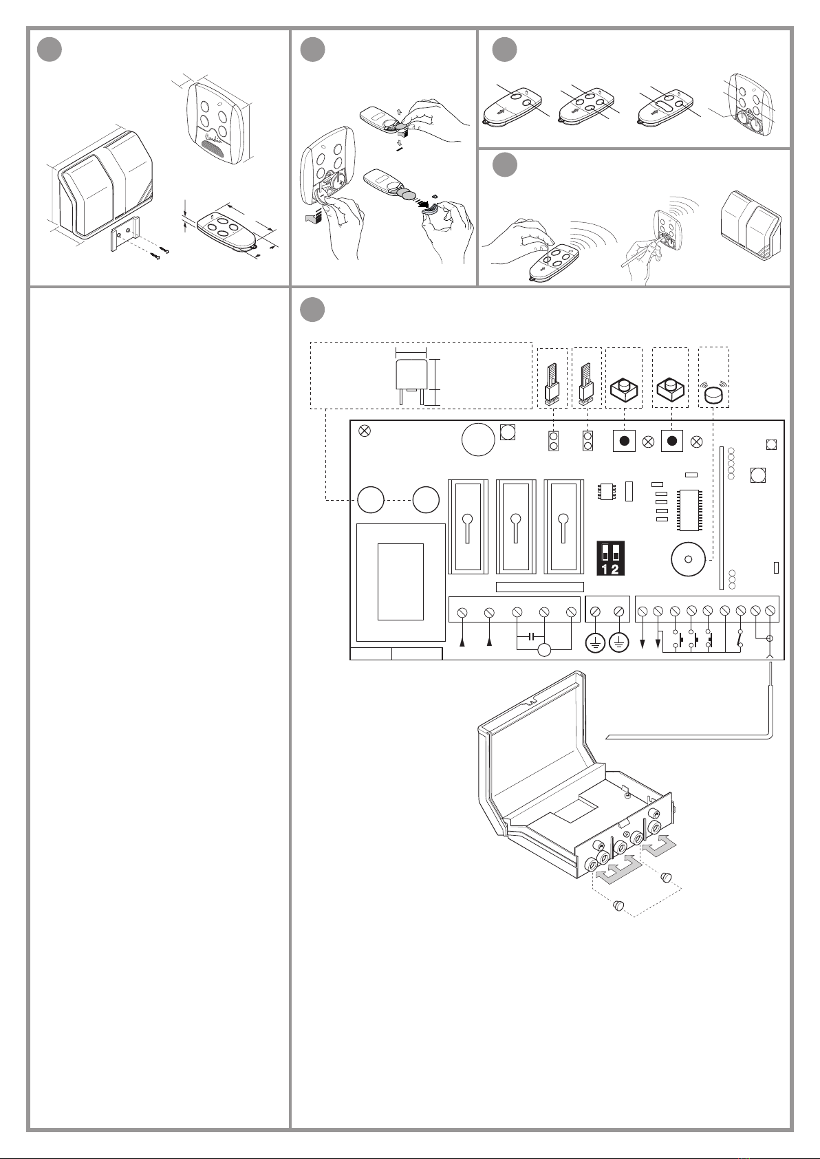
Implantation
Ce dernier devra être positionné de façon telle qu’il soit:
- à l’abri de chocs et d’altérations;
- à une certaine hauteur du sol pour être protégé en cas d’inondation;
- facilement accessible par le technicien en cas d’entretien.
La fixation du récepteur sous coffret devra être effectuée au moyen de l’étrier "fixation rapide". Fixer l’étrier au
mur à l’aide de deux chevilles (prendre soin de mettre à niveau). Une fois que les branchements électriques
ont été effectués, embrocher le coffret sur l’étrier en exerçant une pression sur celui-ci. Pour effectuer l’entre-
tien, il suffit d’exercer, sur le coffret, une pression du bas vers le haut pour le décrocher de l’étrier.
Connexion électrique (fig. 5)
Avant d’effectuer la connexion électrique, contrôler que:
- la tension et la fréquence de la plaquette signalétique correspondent aux données du réseau d’alimenta-
tion;
- un interrupteur bipolaire ayant une ouverture des contacts d’au moins 3 mm soit installé en amont de
l’appareil;
- les câbles de la ligne 230V passent à travers les trous "A" et qu’ils soient séparés des câbles de branche-
ment en basse tension qui passent à travers les trous "B";
- les câbles de branchement soient protégés des contraintes mécaniques.
- une fois la connexion effectuée, contrôler que les trous utilisés pour le passage des câbles soient silico-
nés;
- les trous inutilisés soient fermés par les caches "C" en caoutchouc prévus à cet effet.
- Aux bornes 8…16 pour circuits externes ne doivent être branchés que des circuits à très basse tension.
Branchement du bornier (fig.5)
1-2 Alimentation radioprogrammateur 230Vac 50-60Hz
3-4-5 Sortie commande moteur 600 W Fermeture-Ouverture-Commun
6 Branchement terre moteur
7 Branchement terre alimentation
8-9 Alimentation cellule photoélectrique 24Vac (maxi. 100 mA)
10 Entrée touche d’ouverture "TA" (contact N.O.)
11 Entrée touche de fermeture "TC" (contact N.O.)
12 Entrée touche de blocage "TB" (contact N.F.)
13 Commun pour toutes les entrées
14 Entrée pour sécurité "FTC" (contact N.F.) avec inversion du mouvement en phase de fermeture
15 Masse antenne
16 Branchement antenne
Signalisations et fusibles
L1 LED de signalisation mise sous tension
L2 LED de signalisation gestion codes des émetteurs
L3 LED de signalisation procédé "programmation temps" et signalisation dispositifs de sécurité en état
d’alarme
F1 Fusible 4 A retardé (micro fusible radial)
F2 Fusible 125 mA retardé (micro fusible radial)
Procédé de programmation des temps
-
Temps de travail maxi: 180 secondes
-
Temps de pause maxi: 60 secondes
1) Appuyer sur la touche "P2" PROG et la maintenir appuyée jusqu’à ce que la LED "L3" STATUS s’allume.
2) Fermer complètement le rideau à enroulement au moyen de la touche "P1" MEMO/DEL (l’actionnement
s’effectue en mode de fonctionnement manuel).
3) Appuyer sur la touche "P2" pour lancer la manœuvre d’ouverture.
4) Quand le rideau à enroulement arrive en position d’ouverture complète; et le fin de course en ouverture
s’active, ce qui coupe l’alimentation au moteur et le bloque, attendre 3-4 s, et ensuite appuyer de nouveau
sur "P2": la LED "L3" se met alors à clignoter pour signaler le début du comptage du temps de pause.
5) La pression suivante sur la touche "P2" met fin au comptage du temps de pause et le rideau à enroulement
commence à se fermer.
6) Quand le rideau à enroulement arrive en position de fermeture complète, et le fin de course en fermeture
s’active, ce qui coupe l’alimentation au moteur, attendre 3-4 sec, et ensuite appuyer de nouveau sur la
touche "P2". À ce point, la programmation des temps se termine, et la LED "L3" s’éteint.
Nota: après avoir activé le procédé de programmation, l’opération de l’étape 2 peut aussi être effectuée en
appuyant sur la touche "TC", et celles à partir de l’étape 3 en appuyant sur la touche d’ouverture "TA".
Attention! Si à l’issue de la programmation, les LED "L2" et "L3" clignotent simultanément, le procédé
ne s’est pas conclu correctement, et il faudra refaire la programmation à partir de l’étape 1.
Mode de fonctionnement
(Dip 1 = OFF, Dip 2 = OFF)
- refermeture automatique invalidée
- chaque touche de l’émetteur est affectée à la fonction de commande séquentielle.
Ouverture - Blocage - Fermeture - Blocage.
(Dip 1 = OFF, Dip 2 = ON)
- refermeture automatique invalidée
- les touches de canal de l’émetteur sont affectées à la fonction:
A - Ouverture - B - Fermeture - C - Blocage - D - Séquentielle.
(Dip 1 = ON, Dip 2 = OFF)
- refermeture automatique validée
- les touches de canal de l’émetteur sont affectées à la fonction:
A - Ouverture - B - Fermeture - C - Blocage - D - Séquentielle.
(Dip 1 = ON, Dip 2 = ON)
- mode de fonctionnement manuel en fermeture
- les sécurités "FTC" fonctionnent comme dispositifs de blocage en fermeture
- la commande séquentielle n’est pas acceptée
- les touches de canal de l’émetteur sont affectées à la fonction:
A - Ouverture - B - Fermeture - C - Blocage - D - Sans fonction.
Nota:
- En faisant un pont entre l’entrée "TA" et l’entrée "TC", on transforme l’entrée "TA" en commande séquen-
tielle avec fonction Ouvre-Stop-Ferme-Stop.
- Il est également possible de lancer la manœuvre en manuel (Homme Mort) tout simplement en maintenant
appuyée la touche "TA" (ou la touche "TC") pendant plus d’une seconde.
- Si un quelconque dispositif de sécurité est en état d’alarme (touche de blocage ou cellule photoélectrique),
la LED "L3" clignote rapidement.
CONNECTÉ: les photocellules empêchent également le démarrage du moteur, si elles se trouvent en état
d’alarme.
DÉCONNECTÉ, les photocellules sont activées comme sécurité qu’en phase de fermeture du rideau à enrou-
lement.
Gestion des codes des émetteurs
A. Mémorisation d’un canal
1. Appuyer sur la touche "P1" et la maintenir appuyée: la LED "L2" se met à clignoter lentement, accompa-
gnée d’un signal sonore émis par l’avertisseur.
2. Activer simultanément l'émetteur sur le canal à mémoriser; la LED "L2" clignote 3 fois, accompagnée
d’un signal sonore intermittent, émis par l’avertisseur pour signaler que le canal a été mémorisé. Si la LED
continue à clignoter lentement, le canal a déjà été mémorisé précédemment. Il est possible de mémoriser
qu’un seul canal à la fois. Pour introduire un autre canal, répéter les étapes 1 et 2 après avoir relâché la
touche. Quand la mémoire des codes est pleine (20 émetteurs à 4 touches de mémorisés), il est possible
de mémoriser un nouvel émetteur à condition d’en effacer complètement (toutes les touches) un qui se
trouve en mémoire, ou toute la mémoire.
B. Effacement d’un canal
1. Appuyer deux fois de suite sur la touche "P1"; à la deuxième pression, maintenir la touche appuyée. La
LED "L2" se met alors à clignoter lentement, accompagnée d’un signal sonore émis par l’avertisseur.
2. Activer l’émetteur sur le canal à effacer jusqu’à ce que la LED clignote trois fois, accompagnée d’un signal
sonore intermittent, émis par l’avertisseur.
Répéter les opérations des étapes 1 et 2 pour effacer d’autres canaux, après avoir relâché la touche.
C. Effacement total de la mémoire
Appuyer trois fois de suite sur la touche "P1"; à la troisième pression, maintenir la touche appuyée. Pen-
dant le procédé d’effacement (3-4 secondes), la LED “L2” reste allumée, accompagnée d’un signal sonore
continu, émis par l’avertisseur. À la fin de l’effacement, la LED clignote 3 fois, accompagnée d’un signal
sonore intermittent, émis par l’avertisseur; relâcher alors la touche.
D. Mémorisation par radio d’autres canaux
La mémorisation peut aussi être activée par radio (sans devoir ouvrir le radioprogrammateur) si le cavalier
"J1" est connecté. Les différentes tonalités émises par l’avertisseur sonore donneront une indication claire
sur ce qui se produira.
1) Utiliser une télécommande dont au moins un des canaux a déjà été mémorisé, et activer la touche "PMR"
à l’intérieur de la télécommande (fig. 4).
Nota: tous les récepteurs qui se trouvent dans le rayon d'action de la télécommande et qui ont au moins
un canal de l'émetteur de mémorisé, enclencheront simultanément l'avertisseur acoustique "B1" (fig. 5).
2) Pour sélectionner le récepteur dans lequel il faut mémoriser le nouveau code, activer une des touches de
canal de ce même émetteur. Les récepteurs qui ne contiennent pas le code de cette touche se désactive-
ront, ce qui est signalé par un bip de 5 secondes. Par contre, le récepteur contenant le code émettra un bip
différent qui dure 1 seconde signalant l’accès effectif au procédé de mémorisation "par radio".
3) Appuyer sur la touche de canal choisie précédemment sur l’émetteur à mémoriser. Le récepteur signalera
que la mémorisation a eu lieu en émettant 2 bips d’une demi-seconde. Après quoi, le récepteur sera prêt à
mémoriser un autre code.
4) Pour quitter le procédé de mémorisation "par radio", laisser passer 3 secondes sans mémoriser de codes.
Le récepteur émettra un bip de 5 secondes et quittera le procédé.
Lorsque la mémoire est pleine, le buzzer émet 10 bips très courts, et on sort automatiquement du procédé de
mémorisation "via radio". En outre, le buzzer émettra le même signal sonore chaque fois qu’on essaiera d’accéder
au procédé de mémorisation "via radio" avec mémoire pleine.
12
12
2
1
2
1
Les séries S449 et S486 répondent aux conditions essentielles requises par la
directive 99/05/CE et ont été réalisées selon les normes techniques de référence.
Fréquence: 433.92 / 486.3 MHz per les pays
MODÈLE DATE
FASCICULE SÉRIE

S449-S486 RXPR
29-04-2009
ZVL439.02
CARDIN ELETTRONICA spa
Via Raffaello, 36- 31020 San Vendemiano (TV) Italy
Tel: +39/0438.404011-401818
Fax: +39/0438.401831
Http: www.cardin.it
Anweisungen
DieVerwendung und die Installationdieser Geräte müssen unter rigoroser Beachtung der vom Hersteller gegebenen
Anleitungen und der geltenden Sicherheitsvorschriften erfolgen.
Beschreibung
Das Funksteuerungssystem S449 und S486 bestehen aus einem oder mehreren Sendern und aus einem oder
mehreren Empfängern, die gemäß den spezifischen Anforderungen der Anlage kombiniert werden. Beide Serien
setzen ein Kodifizierungssystem, dessen hohe Zuverlässigkeit durch die Verwendung von dynamischen Codes
gewährleistetist,ein.Bei jeder Übertragung ändert sichder Code gemäß einem Algorithmus,und nur der Empfänger
ist in der Lage, ihn zu erkennen und zu entscheiden, ob die Übertragung im Vergleich mit dem Originalcode korrekt
ist. Der Empfänger kann bis zu 20 verschiedene Codes in einen nichtflüchtigen Speicher speichern. Da es sich um
ein System mit dynamischen Codes handelt, wird jeder Code einzeln vom Empfänger verwaltet.
Wichtig: Es handelt sich hier um ein Gerät, das sich eines hochsicheren Kodifizierungssystems bedient. Der
Verlust von einem oder mehreren Funksteuerungen hat zwangsweise die Neuprogrammierung der Systemcodes
zur Folge, um ihre Untastbarkeit beizubehalten.
Anwendungsmöglichkeiten
Die Funksteuerung ermöglicht die Fernbedienung eines Einphasenmotors 230Vac 600 W.
Sender-Versionen
TRQ449100
(TRQ486100)
Handsender 1 Taste
TRQ449200
(TRQ486200)
Handsender 2 Tasten
TRQ449300
(TRQ486300)
Handsender 3 Tasten
TRQ449400
(TRQ486400)
Handsender 4 Tasten
TRQ44940M
(TRQ48640M)
Wandsender 4 Tasten
Empfänger-Versionen
RPQ449
(RPQ486)
Funksteuerung
Antenne
Um einen optimalen Betrieb der Funksteuerung zu gewährleisten ist die Installation der Antenne von äußerster
Wichtigkeit.Esmusseine passende Antenne mittels einem KoaxialkabelRG58 (Impedanz 50Ω)mit einer maximalen
Länge von 15 m an den Empfänger angeschlossen werden. Die Antenne wird im Freien am höchsten und sicht-
barsten Punkt von Metallstrukturen entfernt, positioniert. Es ist ratsam, den Empfänger in gebührendem Abstand
zu Computersystemen, Alarmanlagen und anderen möglichen Störungsquellen aufzustellen.
Positionierung
Die Anbringstelle des Gerätes sollte folgenden Anforderungen gerecht werden:
- geschützt vor Stößen und Beschädigungen
- ausreichender Abstand vom Boden, geschützt vor möglichem Hochwasser
- an einer für den Techniker für Wartungseingriffe leicht zugänglichen Stelle.
Die Befestigung der Gehäuse erfolgt mittels eines "Schnellbefestigungsbügels".
Der Haltebügel wird mit zwei Dübeln (auf die waagerechte Ausrichtung achten) an der Wand befestigt. Nach
Ausführung der elektrischen Anschlüsse wird das Gehäuse durch Einrasten auf dem Haltebügel angebracht.
Im Falle von Wartungsarbeiten genügt ein auf das Gehäuse ausgeübter Druck von unten nach oben, um das
Gehäuse aus dem Haltebügel an der Wand auszuhaken.
Elektrischer Anschluss (Abb. 5)
Vor dem Ausführen des elektrischen Anschlusses kontrollieren, ob:
- die auf dem Geräteschild angegebene Stromspannung und-frequenz mit der der Stromversorgung überein-
stimmt;
- ein zweipoliger Schalter dem Gerät vorgeschaltet ist, der in offener Stellung mindestens 3 mm Abstand zwi-
schen den Kontakten ermöglicht;
- die Stromversorgungskabel 230V getrennt von den Niederspannungsanschlusskabeln durch die Öffnungen
"A" geführt werden und die Niederspannungskabel stattdessen durch die Öffnungen "B" verlaufen;
- die Anschlusskabel vor mechanischen Schäden geschützt wurden;
- nach der Ausführung der Anschlüsse die für den Durchlass verwendeten Öffnungen mit Silikon versiegelt
worden sind;
- die nicht verwendeten Öffnungen mit den Gummistöpsel "C" geschlossen worden sind.
- An die Klemmen (8…16) für die externen Schaltungen dürfen nur Schaltungen mit niedrigster Spannung ange-
schlossen werden.
Anschlussklemmleiste (Abb. 5)
1-2 Stromversorgung Funksteuerung 230 Vac 50-60 Hz
3-4-5 Ausgang Motorensteuerung 600 W Schließen-Öffnen-Gemeinsam
6 Anschluss Motorerdung
7 Anschluss Stromversorgungserdung
8-9 Stromversorgung Lichtschranken 24Vac (max. 100 mA)
10 Eingang Öffnungstaste "TA" (Einschaltglied-Kontakt)
11 Eingang Schließtaste "TC" (Einschaltglied-Kontakt)
12 Eingang Stopptaste "TB" (Ausschaltglied-Kontakt)
13 Gemeinsam für alle Eingänge
14 Eingang für Sicherheitsvorrichtungen "FTC" (Ausschaltglied-Kontakt) mit Bewegungsumkehrung
während der Schließung
15 Außenleiter der Antenne
16 Innenleiter der Antenne
Mitteilungen und Schmelzsicherungen
L1 LED für Stromversorgung
L2 LED für Sendercodesverwaltung
L3 LED für Zeitenprogrammierungsverfahren und Sicherheitsvorrichtungen im Alarmzustand
F1 Verzögerte Schmelzsicherung 4 A (Radial-Mikroschmelzsicherung)
F2 Verzögerte Schmelzsicherung 125 mA (Radial-Mikroschmelzsicherung)
Zeitenprogrammierungsverfahren
- Arbeitszeitregelung max: 180 Sekunden
- Pausezeitregelung max: 60 Sekunden
1) Die Taste "P2" PROG drücken und bis zum Aufleuchten der LED "L3" STATUS gedrückt halten.
2) Den Rollladen mit der Taste "P1" MEMO/DEL vollkommen schließen (die Betätigung wird im Betriebsmodus
"manuell" ausgeführt).
3) Zum Starten der Öffnungsbewegung die Taste "P2" drücken.
4) Wenn der Rollladen zur vollkommenen Öffnung kommt und der dadurch aktivierte Öffnungsendschalter die
Stromversorgung des Motors abschaltet, 3-4 Sekunden abwarten und dann erneut die "P2" drücken. Die
"L3" zeigt nun durch Blinken an, dass mit der Pausenzeitzählung begonnen worden ist.
5) Durch das nochmalige Drücken der "P2" wird die Pausenzeitzählung beendet und der Schließvorgang des
Rollladens beginnt.
6) Wenn der Rollladen zur vollkommenen Schließung kommt und der dadurch aktivierte Schließungsendschalter
die Stromversorgung des Motors abschaltet, 3-4 Sekunden abwarten und dann erneut die Taste "P2"
drücken. Jetzt ist die Zeitenprogrammierung abgeschlossen und die LED "L3" erlischt.
Anmerkung: Nach der Aktivierung des Programmierungsverfahrens kann Schritt 2 auch durch Drücken der
Taste "TC" ausgeführt werden, und ab Schritt 3 kann auch durch Drücken der Öffnungstaste "TA" mit dem
Verfahren fortgefahren werden.
Wenn bei Abschluss der Zeitenprogrammierung die LED "L2" und "L3" gleichzeitig blinken,
bedeutet dies, dass das Verfahren nicht erfolgreich abgeschlossen worden ist und die Programmierung ab
Schritt 1 wiederholt werden muss.
Betriebsmodus
(Dip 1 = OFF, Dip 2 = OFF)
- automatische Wiederverschließung abgeschaltet
- jede Kanaltaste des Senders hat die Funktion eines sequenziellen Befehls.
Öffnen - Stopp - Schließen - Stopp.
(Dip 1 = OFF, Dip 2 = ON)
- automatische Wiederverschließung abgeschaltet
- die Kanaltasten des Senders haben die Funktion:
A - Öffnen - B - Schließen - C - Stopp - D - Sequenziell.
(Dip 1 = ON, Dip 2 = OFF)
- automatische Wiederverschließung eingeschaltet
- die Kanaltasten des Senders haben die Funktion:
A - Öffnen - B - Schließen - C - Stopp - D - Sequenziell.
(Dip 1 = ON, Dip 2 = ON)
- Betriebsmodus für manuelle Schließung
- die Sicherheitsvorrichtungen "FTC" bei der Schließung haben eine Stoppfunktion
- der sequentielle Befehl wird nicht akzeptiert
- die Kanaltasten des Senders haben die Funktion:
A - Öffnen - B - Schließen - C - Stopp - D - ohne Funktion.
Anmerkung:
- Durch Überbrückung des Eingangs "TA" mit Eingang "TC" wird Eingang "TA" in einen sequentiellen Befehl
mit der Funktion Öffnen-Stopp-Schließen-Stopp umgewandelt.
- Die "manuelle" Betätigung kann durch das einfache Gedrückthalten für etwas länger als eine Sekunde der
Taste "TA" (oder der Taste "TC") ausgeführt werden.
- Wenn eine der Sicherheitsvorrichtungen in Alarmstellung ist (Stopptaste oder Lichtschranke), blinkt die LED
"L3" schnell.
EINGESETZT: Wenn in Alarmstellung verhindern die Lichyschranken auch die Aktivierung des Motors.
NICHT EINGESETZT: Lichtschranke Beschützungs-Funktionen sind nur bei der Schließung aktiv.
Verwaltung der Sendercodes
A. Speicherung eines Kanals
1. Die Taste "P1" drücken und gedrückt halten: Die LED "L2" blinkt langsam und der Summer gibt gleichzeitig
einen Signalton von sich.
2. Den Sender gleichzeitig auf dem zu speichernden Kanal aktivieren. Die LED "L2" zeigt durch 3-maliges
Blinken bei intermittierendem Summer die Speicherung des Kanals an. Wenn die LED weiterhin langsam
blinkt, bedeutet dies, dass der Kanal schon zuvor gespeichert worden ist. Die Kanäle müssen jeweils einzeln
gespeichert werden. Zur Eingabe des nächsten Kanals müssen die Schritte 1 und 2 nach dem Loslassen der
Taste wiederholt werden.
Wenn der Codespeicher voll ist (20 gespeicherte Sender mit jeweils 4 Tasten) kann ein neuer Sender nur nach
vorheriger, vollständiger Löschung (alle Tasten) eines gespeicherten Senders oder nach der Löschung des
gesamten Speichers gespeichert werden.
B. Löschung eines Kanals
1. Die Taste "P1" zweimal drücken und beim zweiten Mal gedrückt halten. Die LED "L2" blinkt nun in kurzen
Abständen und der Summer gibt gleichzeitig einen Signalton von sich.
2. Den Sender auf dem zu löschenden Kanal aktivieren bis die LED 3-mal blinkt und der Summer dabei einen
intermittierenden Signalton von sich gibt.
Nach dem Loslassen der Taste die Schritte 1 und 2 zur Löschung der anderen Kanäle wiederholen.
C. Löschung des gesamten Speichers
3-mal die Taste "P1" drücken und beim 3. Mal die Taste gedrückt halten: Die LED "L2" leuchtet nun ohne
Unterbrechung während des Löschverfahrens (3-4 Sekunden) und wird dabei durch den Dauerton des
Summers begleitet. Bei Abschluss des Löschverfahrens blinkt die LED 3-mal und der Summer gibt dabei
einen intermittierenden Signalton von sich; jetzt die Taste loslassen.
D. Speicherung weiterer Kanäle über Funk
Wenn der Jumper "J1" eingesetzt ist, kann die Speicherung auch über Funk aktiviert werden (ohne dazu die
Funksteuerung öffnen zu müssen). Der Vorgang wird durch die Aktivierung des Summers angezeigt.
1) Eine Funksteuerung verwenden, bei der mindestens einer der Kanäle schon gespeichert worden ist. Die
"PMR" Taste im Sender wie in Abb. 3,4 angezeigt aktivieren.
Anmerkung: Alle von der Funksteuerung erreichbaren Empfänger und die mindestens einen Kanal des
Senders gespeichert haben, aktivieren gleichzeitig den Summer "B1" (Abb. 5).
2) Zur Wahl des Empfängers, bei dem der neue Code gespeichert werden soll, eine der Kanaltasten des
betreffenden Senders aktivieren. Die Empfänger, die nicht über den Code dieser Taste verfügen, werden
bei Ausgabe eines 5 Sekunden dauernden Bip-Tones disaktiviert, während diejenigen, die über den Code
verfügen, einen andersartigen, 1 Sekunden andauernden Bip-Ton von sich geben und nun effektiv in den
"funkgesteuerten" Speichermodus eintreten.
3) Die vorab gewählte Taste des zu speichernden Kanals auf dem Sender drücken. Nach erfolgter Speicherung
lässt der Empfänger 2 Bip-Töne für jeweils eine halbe Sekunde ertönen; danach ist der Empfänger wieder für
die Speicherung eines anderen Codes bereit.
4) Zum Austritt aus dem Speichermodus 3 Sekunden verstreichen lassen, ohne einen Code zu speichern; der
Empfänger wird nun einen 5 Sek. dauernden Bip-Ton abgeben und aus dem Speichermodus austreten.
Wenn der Speicher vollkommen belegt ist, lässt der Summer 10 "Bip"-Töne in rascher Folge ertönen und es erfolgt
automatisch der Austritt aus dem Speichermodus "über Funk". Die gleiche akustische Meldung erfolgt auch bei
jedem Versuch in den Speichermodus "über Funk" einzutreten, wenn der Speicher vollkommen belegt ist.
12
12
2
1
2
1
DieSerien S449 und S486 entsprechenden von der Bestimmung 99/05/CEfestgelegten grund-
sätzlichen Anforderungen und bei ihnen wurden die technischen Bezugsnormen angewandt.
Frequenzbereich: 433.92/486.3 für alle Länder der
MODELL DATUM
ART.-NR SERIE

S449-S486 RXPR
29-04-2009
ZVL439.02
CARDIN ELETTRONICA spa
Via Raffaello, 36- 31020 San Vendemiano (TV) Italy
Tel: +39/0438.404011-401818
Fax: +39/0438.401831
Http: www.cardin.it
6) Cuando la reja se cierra por completo, y entra en acción el final de recorrido del cierre que desalimenta el
motor, bloqueándolo, esperar 3-4 segundos y después apretar "P2"; en este momento la programación
de tiempos ha terminado y el indicador "L3" se apaga.
Nota: después de haber activado el proceso de programación, el paso 2 puede ser efectuado también
apretando la tecla "TC", y del paso 3 en adelante se puede seguir también activando la tecla de apertura
"TA".
¡ATENCIÓN! Si al final de la programación, los indicadores "L2" y "L3" parpadean a la vez, quiere decir
que la operación no ha dado resultado y será necessario repetir la programación desde el paso 1.
Modalidad de funcionamiento
• Semi automático
(Dip 1 = OFF, Dip 2 = OFF)
-
cierre automático desactivado
- cada una de las teclas canal del transmisor tiene la función de mando en secuencia.
Apertura - Bloqueo - Cierre - Bloqueo.
• Semi automático
(Dip 1 = OFF, Dip 2 = ON)
-
cierre automático desactivado
- las teclas canal del transmisor tienen la función:
A - Apertura - B - Cierre - C - Bloqueo - D - Secuencia.
• Automático
(Dip 1 = ON, Dip 2 = OFF)
-
cierre automático activado
- las teclas canal del transmisor tienen la función:
A - Apertura - B - Cierre - C - Bloqueo - D - Secuencia.
• Manual
(Dip 1 = ON, Dip 2 = ON)
-
funcionamiento manual en el cierre
- los seguros "FTC" actúan como bloqueo en el cierre
- no se permite la señal en secuencia
- las teclas canal del transmisor tienen la función:
A - Apertura - B - Cierre - C - Bloqueo - D - Sin función.
Nota:
- Puenteando juntas la entrada "TA" y la entrada "TC" se transforma la entrada "TA" en señal en secuencia
con función Abre -Stop-Cierra-Stop.
- La maniobra "manual" es factible también simplemente teniendo apretada durante más de un segundo
la tecla "TA" (o la tecla "TC").
- Si algún seguro está en situación de alarma (tecla de bloqueo o fotocélula) el indicador "L3" parpadea
velozmente.
CONECTADO las fotocélulas impiden incluso la activación del motor si están en situación de alarma.
DESCONECTADO fotocélulas activas como protección sólo cuando se produce el cierre de la reja.
Gestión de los códigos de los transmisores
A. Memorización de un canal
1. Apretar y mantener apretada "P1"; "L2" parpadea lentamente acompañado del sonido del señalador
acústico.
2. Activar a la vez el transmisor en el canal que se ha de memorizar, el indicador "L2" parpadea 3
veces acompañado del sonido intermitente del señalador acústico evidenciando que el canal ha
sido memorizado; si el indicador sigue parpadeando lentamente, quiere decir que el canal ha sido ya
memorizado en precedencia. Sólo se puede memorizar un canal cada vez. Para introducir un canal
sucesivo repetir los puntos 1 y 2 después de haber soltado la tecla.
Cuando la memoria códigos ha sido completada (20 transmisores con 4 teclas cada uno memorizados) es
posible la memorización de un nuevo transmisor solamente después de haber cancelado completamente
(todas las teclas) uno existente o mediante la cancelación completa de la memoria.
B. Cancelación de un canal.
1. Apretar dos veces la tecla "P1"; en la segunda presión mantener apretada la tecla: el indicador "L2"
parpadea con impulsos breves acompañado del sonido del señalador acústico.
2. Activar el transmisor en el canal que se ha de cancelar, hasta que el indicador parpadee 3 veces
acompañado del sonido intermitente del señalador acústico.
Repetir los puntos 1 y 2 para cancelar otros canales después de haber soltado la tecla.
C. Cancelación completa de la memoria
Apretar 3 veces la tecla "P1"; cuando se presione por tercera vez mantener apretada la tecla. Durante el
proceso de cancelación (3-4 segundos) el indicador "L2" permanece encendido acompañado del sonido
continuo del señalador acústico. Al final de la cancelación el indicador parpadea 3 veces acompañado
del sonido intermitente del señalador acústico; en este momento soltar la tecla.
D. Memorización de ulteriores canales vía radio
La memorización puede ser también activada vía radio (sin abrir el radio programador) si el jumper "J1" ha
sido conectado. La señal de todo esto tiene lugar a través de la puesta en funcionamiento del señalador
acústico.
1) Utilizando un radiomando en el cual al menos uno de los canales haya sido ya memorizado, activar la
tecla "PMR" en el interior del radiomando (fig. 3,4).
Nota: todos los receptores alcanzables por la emisión del radiomando, y que tengan al menos un canal del
transmisor memorizado, activarán al mismo tiempo el avisador acústico "B1" (fig. 5).
2) Para seleccionar el receptor en el que memorizar el nuevo código activar una de las teclas de canal del
mismo transmisor . Los receptores que no contengan el código de dicha tecla se desactivarán con la
emisión de un "bip" de 5 segundos de duración; sin embargo el que contenga el código emitirá otro "bip"
que durará un segundo, entrando de hecho en la modalidad de memorización "vía radio".
3) Apretar la tecla del canal precedentemente elegido en el transmisor que se ha de memorizar; realizada la
memorización el receptor emitirá 2 "bip" de medio segundo, después de esto el receptor estará listo para
memorizar otro código.
4) Para salir de la modalidad dejar pasar 3 segundos sin memorizar códigos, el receptor emitirá un "bip" de
5 segundos de duración y saldrá de la modalidad.
Cuando la memoria está totalmente ocupada, el avisador acústico emitirá 10 "bips" cercanos, saliendo
automáticamente de la modalidad de memorización "vía radio"; la misma señalización sonora se obtiene también
tras cada tentativa de entrar en la modalidad "vía radio" con la memoria totalmente ocupada.
RADIO PROGRAMADOR DIGITAL DE CODIGOS DINAMICOS S449
Advertencias
El uso y la instalación de este equipo deben cumplir rigurosamente con las indicaciones facilitadas por el
fabricante y las vigentes normas de seguridad.
Descripción
Los sistemas de mando a distancia S449 y S486 están compuestos por uno o más transmisores y de uno o
más receptores que se combinarán en función de las exigencias específicas de la instalación. Ambas series
usan un sistema de codificación de gran fiabilidad garantizada por el uso de códigos dinámicos. Para cada
transmisión el código cambia con base en un algoritmo que sólo el receptor puede reconocer y establecer si
la transmisión es correcta respecto al código original. En el receptor se pueden almacenar hasta 20 códigos
diferentes en una memoria no volátil. Tratándose de un sistema de códigos dinámicos, cada código es
gobernado individualmente por el receptor.
Importante: Estos aparatos de valen de un un sistema de codificación muy seguro, por tanto si se pierde uno
o varios radiomandos, es preciso volver a programar los códigos del sistema para mantener su inviolabilidad.
Posibilidad de empleo
El radio programador permite el mando a distancia de un motor monofásico de 230Vac 600 W.
Modelos de transmisores
TRQ449100 (TRQ486100) Transmisores de bolsillo 1 tecla
TRQ449200 (TRQ486200) Transmisores de bolsillo 2 teclas
TRQ449300 (TRQ486300) Transmisores de bolsillo 3 teclas
TRQ449400 (TRQ486400) Transmisores de bolsillo 4 teclas
TRQ44940M (TRQ48640M) Botonera radio para fijación en la pared 4 teclas
Modelos de receptores
RPQ449 (RPQ486) Radio programador
Antena
Para obtener el mejor funcionamiento del radiomando la instalación de la antena es fundamental; conectada
al receptor representa el punto de recepción del radiomando.
Es necesario conectar al receptor una antena acordada mediante un cable coaxial RG58 (imp. 50Ω) de
15m de largo como máximo. La antena se debe colocar al exterior en el sitio más elevado y visible, lejos
de estructuras metálicas. Colocar el receptor a cierta distancia de las redes de sistemas computarizados,
instalaciones de alarma y otras fuentes de perturbaciones posibles.
Emplazamiento
El aparato se debe colocar:
- protegido de choques y manipulaciones
- a una altura desde el suelo suficiente, protegido de los remansos de agua
- en una posición de fácil acceso para el técnico, para las operaciones de mantenimiento.
La fijación del la caja se realiza utilizando el soporte de "fijación rápida".
Fijar el soporte mural por medio de dos tacos (tener cuidado con la puesta a nivel). Finalizadas las conexiones
eléctricas, el contenedor se introduce por presión en el propio soporte.
De ser necesarias algunas operaciones de mantenimiento, es suficiente una presión ejercida sobre la caja
de abajo arriba para que el contenedor se desenganche del soporte mural.
Conexión eléctrica (fig. 5)
Antes de realizar la conexión eléctrica, comprobar que:
- la tensión y la frecuencia indicadas en la placa de características coincidan con las de la instalación de
alimentación;
- está incorporado antes del aparato un interruptor bipolar con apertura de los contactos de 3 mm como
mín.;
- los cables de la línea 230V pasan por los orificios "A", separados de los cables de conexión en baja tensión
que pasan por los orificios "B";
- los cables de conexión están protegidos contra los esfuerzos mecánicos;
- finalizadas las conexiones, los orificios utilizados para el paso de los cables están sellados con silicona;
- los orificios sin utilizar están tapados con los tapones de caucho "C" correspondientes.
- Con los bornes (8…16) para circuitos exteriores se deben conectar únicamente circuitos de bajísima
tensión de seguridad.
Conexión caja bornes
1-2 Alimentación radio programador 230 Vac 50-60 Hz
3-4-5 Salida mando motor 600 W Cierre-Apertura-Común
6 Conexión tierra motor
7 Conexión tierra alimentación
8-9 Alimentación fotocélula 24 Vac (max. 100 mA)
10 Entrada tecla apertura "TA" (contacto N.A.)
11 Entrada tecla cierre "TC" (contacto N.A.)
12 Entrada tecla de bloqueo "TB" (contacto N.C.)
13 Común para todas las entradas
14 Entrada para seguridad "FTC" (contacto N.C.) con inversión en fase de cierre
15 Masa antena
16 Conexión antena
Señales y fusibles
L1 Indicador de la señal de alimentación
L2 Indicador de la señal gestión códigos de los transmisores
L3 Indicador de la señal "procedimiento" programación tiempos y "señales seguridad con alarmas"
F1 Fusible 4 A atrasado (microfusible radial)
F2 Fusible 125 mA atrasado (microfusible radial).
Procedimiento de programación tiempos
- Tiempo de trabajo max: 180 segundos.
- Tiempo de pause max: 60 segundos.
1) Apretar y mantener apretada la tecla "P2" PROG hasta que se encienda el indicador "L3" STATUS.
2) Cerrar completamente el cierre metálico con la tecla "P1" MEMO/DEL (con la modalidad "manual").
3) Apretar la tecla "P2" para empezar la maniobra de apertura.
4) Cuando el cerramiento metálico se abre completamente, y entra en acción el final de recorrido de
apertura que desalimenta el motor, esperar 3-4 segundos y después apretar de nuevo la tecla "P2": el
indicador "L3" empieza a parpadear señalando el principio del cómputo del tiempo de pausa.
5) Una presión sucesiva de la tecla "P2" da fin al cómputo del tiempo de pausa y la reja empieza a
cerrarse.
12
12
2
1
2
1
Las series S449 y S486 cumplen con los requisitos esenciales dispuestos por
la directiva 99/05/CE y se les han aplicado las normas técnicas de referencia.
Frecuencia: 433.92/486.3 MHz para los países del
MODELO FECHA
CODIGO SERIE

CARATTERISTICHE TECNICHE - TECNICAL SPECIFICATIONS
CARACTERISTICAS TECNICAS
Ricevitore
- Alimentazione ..................................................................230Vac, 50-60Hz
- Trasmettitori memorizzabili .....................................................................20
- Temperatura di esercizio ........................................................-20°…+60°C
Trasmettitore
- Frequenza di trasmissione S449..............................................433,92MHz
- Frequenza di trasmissione S486................................................868,3MHz
- Modulazione .................................................................................. FM/FSK
- Alimentazione (batteria litio) ................................................... 2 x CR2032
- Assorbimento..................................................................................... 35mA
- Temperatura di esercizio ........................................................-10°…+55°C
- Tipo di codifica .........................................................................rolling code
- Numero di combinazioni complessive (66 bit) .......................................266
- Numero delle funzioni (canali) ...................................................................4
- Autospegnimento ...............................................dopo almeno 25 secondi
Receiver
- Power supply...................................................................230Vac, 50-60Hz
- Number of stored transmitters................................................................20
- Operating temperature range.................................................-20°…+60°C
Transmitters
- Carrier frequency S449 ............................................................433,92MHz
- Carrier frequency S486 ..............................................................868,3MHz
- Modulation..................................................................................... FM/FSK
- Power supply (lithium battery) ................................................ 2 x CR2032
- Power consumption .......................................................................... 35mA
- Operating temperature range.................................................-10°…+55°C
- Type of encoding ......................................................................rolling code
- Total number of possible code combinations (66 bit)..........................266
- Number of functions (channels)................................................................4
- Automatic shut down .......................................... after at least 25 secondi
Récepteur
- Alimentation .....................................................................230Vac, 50-60Hz
- Émetterurs mémorisables .......................................................................20
- Température de fonctionnement............................................-20°…+60°C
Émetteur
- Fréquence porteuse S449........................................................433,92MHz
- Fréquence porteuse S486..........................................................868,3MHz
- Modulation..................................................................................... FM/FSK
- Alimentation (pile au lithium) ................................................... 2 x CR2032
- Absorption ......................................................................................... 35mA
- Température de fonctionnement............................................-10°…+55°C
- Type de décodage....................................................................rolling code
- Nbre total de combinaisons (66 bits)....................................................266
- Nbre de fonctions (canaux) .......................................................................4
- Autoextinction ............................................. après au moins 25 secondes
Empfänger
- Stromversorgung.............................................................230Vac, 50-60Hz
- Speichbare Handsenders .......................................................................20
- Betriebstemperatur.................................................................-20°…+60°C
Sender
- Trägerfrequenz S449 ................................................................433,92MHz
- Trägerfrequenz S486 ..................................................................868,3MHz
- Modulation..................................................................................... FM/FSK
- Versorgung (Lithium-Batterie) ................................................. 2 x CR2032
- Bedarf................................................................................................. 35mA
- Betriebstemperatur.................................................................-10°…+55°C
- Dekodierungsart .....................................................................Rolling Code
- Anzahl aller Kombinationsmöglichkeiten (66 Bit) ...................................266
- Anzahl der Kanäle......................................................................................4
- Selbstausschaltung ..................................nach mindestens 25 Sekunden
Receptor
- Alimentación ....................................................................230Vac, 50-60Hz
- Emisores memorizables ..........................................................................20
- temperatura de funcionamiento.............................................-20°…+60°C
Emisor
- Frecuencia portadora S449 .....................................................433,92MHz
- Frecuencia portadora S486 .......................................................868,3MHz
- Modulación .................................................................................... FM/FSK
- Alimentación (batería de litio) .................................................. 2 x CR2032
- Absorción........................................................................................... 35mA
- Temperatura de funcionamiento............................................-10°…+55°C
- Tipo de código..........................................................................rolling code
- nr. de combinaciones totales (66 bit)......................................................266
- n° de functiones (canales) .........................................................................4
- autoapagado.............................. después de 25 segundos como mínimo
CH A CH B
PMR
SELEZIONI CANALE 2 TASTI
TRQ449200
10-12-2002
DM0693 Description :
Product Code :
Date :
Drawing number :
P.J.Heath
CARDIN ELETTRONICA S.p.A - 31020 San Vendemiano (TV) Italy - via Raffaello, 36 Tel: 0438/401818 Fax: 0438/401831
Draft :
All rights reserved. Unauthorised copying or use of the information contained in this document is punishable by law
RXPR449
Collegamento contenitore per
radioprogrammatore
07-01-03
DM0700 Description :
Product Code :
Date :
Drawing number :
P.J.Heath
CARDIN ELETTRONICA S.p.A - 31020 San Vendemiano (TV) Italy - via Raffaello, 36 Tel: 0438/401818 Fax: 0438/401831
Draft :
All rights reserved. Unauthorised copying or use of the information contained in this document is punishable by law
B
A
C
12345
M
8910 11 12 13
FTC
CH.
COM
AP.
P1
DC0376 CS1168A
67
L
N
230V~
c
1 2
ON
Antenna filo rigido 17cm
17 cm rigid wire antenna
Antenne fil rigide 17 cm
Starres Antennen Kabel 17 cm
Antena cable rígido 17 cm.
14 15 16
TA
TC
TB
F1
S1
P2
J2
J1
B1
B1
COM
COM
24Vac
F2
Ricevitore in cassetta (fusibile T160mA)
S449
03-12-2003
DC0376 Description :
Product Code :
Date :
Drawing number :
P.J.Heath
CARDIN ELETTRONICA S.p.A - 31020 San Vendemiano (TV) Italy - via Raffaello, 36 Tel: 0438/401818 Fax: 0438/401831
Draft :
All rights reserved. Unauthorised copying or use of the information contained in this document is punishable by law
RXPR S449 - 230V 50-60Hz
L2 L3
R2
L1
7,7
8,35
4.3
F1: Fuse types
Current T4A
BEL MRT4
OMEGA MT785240
F2: Fuse types
Current T160mA
BEL MRT160
OMEGA MT785116
DIMENSIONI D'INGOMBRO - EXTERNAL DIMENSIONS
DIMENSIONS D'ENCOMBREMENT - PLATZBEDARF
DIMENSIONES MÁXIMAS
CAMBIO BATERIA
BATTERY REPLACEMENT
REMPLACEMENT DES PILES
BATTERIEWECHSEL
116
138
45
Dimensioni d'ingombro contenitore
RX046
01-06-2001
DM0042 Description :
Product Code :
Date :
Drawing number :
P.J.Heath
CARDIN ELETTRONICA S.p.A - 31020 San Vendemiano (TV) Italy - via Raffaello, 36 Tel: 0438/401818 Fax: 0438/401831
Draft :
All rights reserved. Unauthorised copying or use of the information contained in this document is punishable by law
1
TRS44940M
02-07-2001
DM0550
CAMBIO BATTERIA
Description :
Product Code :
Date :
Drawing number :
P.J.Heath
CARDIN ELETTRONICA S.p.A - 31020 San Vendemiano (TV) Italy - via Raffaello, 36 Tel: 0438/401818 Fax: 0438/401831
Draft :
All rights reserved. Unauthorised copying or use of the information contained in this document is punishable by law
Cambio batteria 2
TRQ449200
13-04-2001
DM0527 Description :
Product Code :
Date :
Drawing number :
P.J.Heath
CARDIN ELETTRONICA S.p.A - 31020 San Vendemiano (TV) Italy - via Raffaello, 36 Tel: 0438/401818 Fax: 0438/401831
Draft :
All rights reserved. Unauthorised copying or use of the information contained in this document is punishable by law
+
Cambio batteria 1
TRQ449200
13-04-2001
DM0526 Description :
Product Code :
Date :
Drawing number :
P.J.Heath
CARDIN ELETTRONICA S.p.A - 31020 San Vendemiano (TV) Italy - via Raffaello, 36 Tel: 0438/401818 Fax: 0438/401831
Draft :
All rights reserved. Unauthorised copying or use of the information contained in this document is punishable by law
TRS44940M
02-07-2001
DM0549
DIMENSIONI D'INGOMBRO
Description :
Product Code :
Date :
Drawing number :
P.J.Heath
CARDIN ELETTRONICA S.p.A - 31020 San Vendemiano (TV) Italy - via Raffaello, 36 Tel: 0438/401818 Fax: 0438/401831
Draft :
All rights reserved. Unauthorised copying or use of the information contained in this document is punishable by law
72
15
72
TRS44940M
02-07-2001
DM0696
SELEZIONE CANALI
Description :
Product Code :
Date :
Drawing number :
P.J.Heath
CARDIN ELETTRONICA S.p.A - 31020 San Vendemiano (TV) Italy - via Raffaello, 36 Tel: 0438/401818 Fax: 0438/401831
Draft :
All rights reserved. Unauthorised copying or use of the information contained in this document is punishable by law
CH A
CH B
CH C
CH D
PMR
CH A
CH B
CH C
CH D
SELEZIONI CANALE 4 TASTI
TRQ449200
10-12-2002
DM0695 Description :
Product Code :
Date :
Drawing number :
P.J.Heath
CARDIN ELETTRONICA S.p.A - 31020 San Vendemiano (TV) Italy - via Raffaello, 36 Tel: 0438/401818 Fax: 0438/401831
Draft :
All rights reserved. Unauthorised copying or use of the information contained in this document is punishable by law
PMR
3
CH A CH B
PMR
CH C
SELEZIONI CANALE 3 TASTI
TRQ449200
10-12-2002
DM0694 Description :
Product Code :
Date :
Drawing number :
P.J.Heath
CARDIN ELETTRONICA S.p.A - 31020 San Vendemiano (TV) Italy - via Raffaello, 36 Tel: 0438/401818 Fax: 0438/401831
Draft :
All rights reserved. Unauthorised copying or use of the information contained in this document is punishable by law
2
Legenda
A: Ingresso cavi 230Vac
B: Ingresso cavi 24Vac
C: Tappi in gomma
L1: LED di alimentazione
L2: LED di segnalazione gestione codici trasmettitori
L3: LED di segnalazione "programmazione
tempi" e "sicurezze in allarme"
S1: Dip switch di "selezione modalità
funzionamento"
B1: Buzzer di segnalazione acustica
P1: Tasto di memorizzazione codici
P2: Tasto di programmazione tempi
J1: Jumper di selezione memorizzazione radio
J2: Jumper di selezione attivazione fotocellule
72
11
34
DIMENSIONI D'INGOMBRO
TRQ449200
13-04-2001
DM0523 Description :
Product Code :
Date :
Drawing number :
P.J.Heath
CARDIN ELETTRONICA S.p.A - 31020 San Vendemiano (TV) Italy - via Raffaello, 36 Tel: 0438/401818 Fax: 0438/401831
Draft :
All rights reserved. Unauthorised copying or use of the information contained in this document is punishable by law
Legend
A: Entry holes for 230Vac mains wiring
B: Entry holes for low voltage 12/24V wiring
C: Hole sealing plugs
L1: Power on LED
L2: Transmitter code management LED
L3: Time programming indicator and security device alarm LED
S1: Dip-switch "function mode selection"
B1: Accoustic buzzer
P1: Code morisation button
P2: Time programming button
J1: Memorisation via radio jumper
J2: Photocell activation selection jumper
Nomenclature
A: Entrée câble de branchement 230Vac
B: Entrée câble de branchement 24Vac
C: Caches
L1: LED de signalisation mise sous tension
L2: LED de signalisation gestion code des émetteurs
L3: LED de signalisation “programmation temps”
et "dispositif de securité en état d’alarme"
S1: dip switch de sélection "mode de fonctionnement"
B1: avertisseur sonore
P1: Bouton de mémorisation codes
P2: Bouton de programmation temps
J1: Cavalier de sélection mémorisation par radio
J2: Cavalier de sélection activation photocellules
Zeichenerklärung
A: Eingang 230Vac Anschlusskabel
B: Eingang 24Vac Anschlusskabel
C: Stöpsel
L1: LED für Stromversorgung
L2: LED für Sendercodesverwaltung
L3: LED für Zeitenprogrammierungsverfah-
ren und Sicherheitsvorrichtungen im
Alarmzustand
S1: Dip-Schalter zum wählen dem
"Betriebsmodus"
B1: Summer zur akustischen Signalisierung
P1: Code-Speichertaste
P2: Zeitenprogrammiertaste
J1: Jumper für ferngesteuerte Speicherung
J2: Jumper zur wählen der
"Lichtschranke-Funktion"
5
COLLEGAMENTO ELETTRICO RADIOPROGRAMMATORE - RADIO PROGRAMMER ELECTRICAL CONNECTION
CONEXIÓN ELÉCTRICA RADIO PROGRAMADOR
Leyenda
A: Entrada cables de conexión 230Vac
B: Entrada cables de conexión 24Vac
C: Tapones
L1: Indicador luminoso de la señal de alimenta-
ción
L2: Indicador luminoso de la señal
"gestión códigos emisores"
L3: Indicador luminoso de la señal
procedimiento "programación tiempos" y
"señales seguridad con alarmas"
S1: Dip-switch para "selecciones
modalidad funcionamiento
B1: Avisador acùstico
P1: Tecla de memorización codigos
P2: Tecla de programación tiempos
J1: Jumper de memorización por radio
J2: Jumper de activación fotocélulas
MEMORIZZAZIONE VIA RADIO - MEMORISATION VIA RADIO
MÉMORISATION PAR RADIO
MEMORIZACIÓN POR RADIO
4
SELEZIONE DEI CANALI - CHANNEL SELECTION - DISPOSITION
LOS CANALES
Radioprogrammatore S449
Memorizzazione via radio
RPQ449
28-03-02
DM0054 Description :
Product Code :
Date :
Drawing number :
P.J.Heath
CARDIN ELETTRONICA S.p.A - 31020 San Vendemiano (TV) Italy - via Raffaello, 36 Tel: 0438/401818 Fax: 0438/401831
Draft :
All rights reserved. Unauthorised copying or use of the information contained in this document is punishable by law
MEMORIZZAZIONE CODICE TX-RX
RCQ449100
13-04-2001
DM0531 Description :
Product Code :
Date :
Drawing number :
P.J.Heath
CARDIN ELETTRONICA S.p.A - 31020 San Vendemiano (TV) Italy - via Raffaello, 36 Tel: 0438/401818 Fax: 0438/401831
Draft :
All rights reserved. Unauthorised copying or use of the information contained in this document is punishable by law
MR
TRS44940M
02-07-2001
DM0551
MEMORIZZAZIONE CODICI
Description :
Product Code :
Date :
Drawing number :
P.J.Heath
CARDIN ELETTRONICA S.p.A - 31020 San Vendemiano (TV) Italy - via Raffaello, 36 Tel:0438/401818 Fax: 0438/401831
Draft :
All rights reserved. Unauthorised copying or use of the information contained in this document is punishable by law
Other manuals for S449 Series
7
This manual suits for next models
1
Table of contents
Languages:
Other Cardin Elettronica Motherboard manuals