manuals.online logo
Brands
  1. Home
  2. •
  3. Brands
  4. •
  5. Carel
  6. •
  7. Media Converter
  8. •
  9. Carel Pc-GATE RS232 User manual

Carel Pc-GATE RS232 User manual

94
128 38.6
152
Power
12Vac
RS 232
GND
IN
PC connections
RS485 network
Rx Tx Power
Rx Tx
Thank you for your choice. We trust you will be satisfied with your purchase.
The Carel Pc-GATE is an electronic device for:
- connecting all Carel controllers in an RS485 network to a RS232 serial port on a PC;
- doubling the RS485 line;
- amplifying/regenerating the signal in a section of the RS485 line.
The Pc-GATE manages a maximum of 200 network devices.
RS232 - RS485 converter
The Pc-GATE converts the RS232C protocol to Carel RS485 without requiring special drivers for Windows.
The typical configuration used for this function is shown in fig. 5.
One Pc-GATE can be used to run two separate RS485 lines.
Protection key function
All versions of the Pc-GATE, with the exception of model CVSTD00000, feature a software protection function, which ena-
bles the supervisor program on the PC it is connected to.
Watchdog function
The Pc-GATE analyses the structure of the packets transmitted, checking its coherence and compatibility with the Carel
protocol. If there is no communication, or there is a persistent error, it signals this event via an alarm output, which may be
activated for a set time or permanently energised. The error status is reset when correct communication resumes.
RS485 shunt
The Pc-GATE sends the data packets automatically from the IN line to the OUT1 and OUT2 lines.
The typical configuration is shown in fig.5.
The units connected to OUT1, OUT2 can have any address. Up to 2 Pc-GATEs can be connected in a cascading configu-
ration. The IN line is optically-isolated and regenerated on lines OUT1 and OUT2 .
The two OUT lines are not optically-isolated between each other.
Configuration
DIP ON OFF
1 19200 b/s 9600 b/s
2 Not used Not used
3 Not used Not used
4 Not used Not used
5 Not used Not used
6 ADR2 weight 0 ADR2 weight 4
7 ADR1 weight 0 ADR1 weight 2
8 ADR0 weight 0 ADR0 weight 1
ADR2,1,0 must be 0; to be defined or future uses.
The address 200 disables the function for setting the address of the converter.
Default settings
The default parameter settings are:
• All dipswitches at ON, down;
• baudrate: 19200;
• communication mode: N,8,2 ;
• no communication timeout: 20 min;
• relay closing time in the event of alarms: 10 s.
User interface
Features 4 red LEDs on the top upper.
LED OFF ON
power (green) OFF ON
Rx net (red) Data Rx = 0 Data Rx = 1
Tx net (red) Data Tx = 0 Data Tx = 1
Rx PC (red) Data Rx = 0 Data Rx = 1
Tx PC (red) Data Tx = 0 Data Tx = 1
Technical specifications
Power supply: External 12 Vac -15%…+10%, 50/60 Hz
Ratings relè: 2(2) A/250 Vac
UL: 2A 250 Vac
Alarm digital input from voltage free contact normally closed for remote alarm activation.
Contact current >20 mA.
Connect the Pc-GA
TE power supply cable before connecting it to the power supply of the network.
Installations
• Desktop installation:
AC mini jack, dia. 5 mm. ONLY use the special power supply adapter supplied by Carel upon request. The use of other
adapters may damage the hardware.
Vi ringraziamo della scelta fatta, sicuri che sarete soddisfatti del vostro acquisto.
Il Pc-GATE Carel è un dispositivo elettronico che permette di:
- collegare di tutti i controllori Carel di una rete RS485 ad una seriale PC RS232;
- sdoppiare la linea RS485;
- amplificare/rigenerare il segnale su un tratto di linea RS485.
Pc-GATE gestisce al massimo 200 dispositivi in rete.
Convertitore RS232 - RS485
Pc-GATE converte il protocollo RS232C in RS485 Carel senza utilizzare particolari driver per Windows.
la tipica configurazione che è prevista per questa funzionalità è riportata in fig. 5.
Con un solo Pc-GATE si ottiene anche la possibilità di avere due linee RS485 separate.
Funzionalità chiave di protezione
Tutti i Pc-GATE, eccetto il modello CVSTD00000, sono dotati della funzione di protezione del software che abilita
l’esecuzione del programma di supervisione sul PC cui è collegato.
Funzionalità di watchdog
Il Pc-GATE analizza la struttura dei pacchetti che passano verificandone la coerenza e la compatibilità con il protocollo
Carel. Segnala l’assenza di comunicazione o un errore persistente con una uscita di allarme che può essere temporizzata
con tempo programmabile o permanentemente eccitata. Si esce dalla situazione di errore se viene ristabilita la
comunicazione corretta.
Derivatore RS485
Pc-GATE instrada i pacchetti della comunicazione in modo automatico dalla linea IN verso le linee OUT1 e OUT2.
La configurazione tipica è riportata in fig. 5.
Gli indirizzi delle macchine nei lati OUT1, OUT2 possono assumere qualsiasi valore. Si possono mettere in cascata al
massimo 2 Pc-GATE. La linea IN viene optoisolata e rigenerata nelle due linee OUT1 e OUT2.
Le due linee OUT non sono tra loro optoisolate.
Configurazione
DIP ON OFF
1 19200 b/s 9600 b/s
2 Non usato Non usato
3 Non usato Non usato
4 Non usato Non usato
5 Non usato Non usato
6 ADR2 peso 0 ADR2 peso 4
7 ADR1 peso 0 ADR1 peso 2
8 ADR0 peso 0 ADR0 peso 1
ADR2/1/0 devono essere a 0; da definire, per usi futuri.
Impostazioni di default
I parametri di default sono:
• Tutti i dip a ON verso il basso;
• baude rate: 19200;
• modo comunicazione: N,8,2;
• time-out mancanza comunicazione: 20 min;
• tempo di chiusura relè in caso di allarme: 10 s.
Interfaccia utente
Prevede 4 LED rossi e 1 verde sul lato superiore.
LED SPENTO ACCESO
power (verde) non alimentato alimentato
Rx net (rosso) Dato Rx = 0 Dato Rx = 1
Tx net (rosso) Dato Tx = 0 Dato Tx = 1
Rx PC (rosso) Dato Rx = 0 Dato Rx = 1
Tx PC (rosso) Dato Tx = 0 Dato Tx = 1
Caratteristiche Tecniche
Alimentazione: Esterna 12 Vac -15%…+10%, 50/60 Hz
Ratings relè: 2(2) A/250 Vac
UL: 2A 250 Vac
Ingresso digitale di allarme da contatto pulito normalmente chiuso per attivazione dell'allarme da remoto.
Corrente del contatto >20 mA
Collegare il cavo di alimentazione del Pc-GATE prima di averlo connesso all’alimentazione della rete elettrica.
Installazione
• Installazione su tavolo:
tramite presa AC mini, ø5 mm. Utilizzare ESCLUSIVAMENTE l’apposito adattatore di alimentazione fornito da Carel.
L’utilizzo di adattatori diversi può provocare danni all’hardware.
cod. +050000880 - rel.1.1 - 30/09/2003
CVSTD00000: Pc-GATE - Convertitore seriale RS232/RS485 / Pc-GATE - Serial converter RS232/RS485
Dimensioni / Dimensions
Connessioni / Connections
Configurazione / Configurations
Fig. 1
Fig. 2
Fig. 3
CAREL S.p.A.
Via dell’Industria, 11 - 35020 Brugine - Padova (Italy)
Tel. (+39) 0499716611 – Fax (+39) 0499716600
http://www.carel.com – e-mail: [email protected]
Carel si riserva la possibilità di apportare modifiche o cambiamenti ai propri prodotti senza alcun preavviso.
Carel reserves the right to modify the features of its products without prior notice.
cod. +050000880 - rel.1.1 - 30/09/2003
• Montaggio a pannello:
tramite morsetti orizzontali removibili a 2 vie (passo 5,08 mm), dimensioni dei fili 0,5-1,5 mm2. Caratteristiche del fusibile
(obbligatorio) da installare in serie all’alimentatore dell’unità: 500 mAT. Utilizzare un trasformatore di sicurezza in classe 2
di almeno 6 VA. Potenza nominale: 3 W. È consigliato l’uso del trasformatore fornito da Carel.
Interfacce:
• seriale RS485, opto-isolata, morsetti orizzontali removibili a 3 vie (passo 5.08 mm), dimensioni dei fili: 0,14-1,5 mm2.
Utilizzare un doppino ritorto schermato, AWG20-22, max. 1000 m.
• seriale RS232 DTE, connettore DB-9 maschio a 9 vie; 19200 baud 8 bit di dati, 2 bit di stop, nessuna parità e nessun
controllo flusso. Utilizzare un cavo null modem, max. 10 m.
Caratteristiche funzionali:
Protocolli standard supportati: Carel 5.0 e seguenti.
Caratteristiche generali:
Condizioni di funzionamento 0T50°C, 0 a 90% U.R. non condensante
Condizioni di immagazzinamento -10T70°C, 0 a 90% U.R. non condensante
Grado di Protezione (IP): IP20
Dimensioni (mm): 152 x 129 x 39
Inquinamento ambientale: normale
Categoria di resistenza al calore e al fuoco: D
Classe e struttura del software: A
Smaltimento del prodotto:
Il prodotto è composto da parti elettroniche, da parti in metallo e da parti in plastica.
Tutte queste parti vanno smaltite secondo le normative locali in materia di smaltimento.
Avvertenze per l’istallazione
Evitare il montaggio delle schede in ambienti che presentino le seguenti caratteristiche:
• umidità relativa maggiore del 90%;
• forti vibrazioni o urti;
• esposizione a getti d'acqua;
• esposizione ad atmosfere aggressive ed inquinanti (es.: gas solforici e ammoniacali, nebbie saline, fumi) con
conseguente corrosione e/o ossidazione;
• elevate interferenze magnetiche e/o radiofrequenze (evitare quindi l'installazione delle macchine vicino ad antenne
trasmittenti);
• esposizione all'irraggiamento solare diretto e agli agenti atmosferici in genere;
• ampie e rapide fluttuazioni della temperatura ambiente;
• ambienti ove sono presenti esplosivi o miscele di gas infiammabili;
• esposizione alla polvere (formazione di patina corrosiva con possibile ossidazione e riduzione dell'isolamento).
Per il collegamento del Pc-GATE è necessario osservare alcune AVVERTENZE:
• Una tensione di alimentazione elettrica diversa da quella prescritta può danneggiare seriamente il sistema.
• Utilizzare capicorda adatti per i morsetti in uso. Allentare ogni vite ed inserirvi i capicorda, quindi serrare le viti.
Ad operazione ultimata tirare leggermente i cavi per verificarne il corretto serraggio.
• Evitare di avvicinarsi con le dita ai componenti elettronici montati sulle schede per evitare scariche elettrostatiche
(estremamente dannose) dall’operatore verso i componenti stessi.
• Panel installation:
removable horizontal 2 wire terminals (step 5.08 mm), cross-section of the wires 0.5-1.5 mm2. Characteristics of the fuse
(compulsory) to be installed in series with the power supply to the unit: 500 mAT. Use a class 2 safety transformer, with a
minimum rating of 6VA. Rated power: 3 W. It is recommended to use the transformer supplied by Carel.
Interfaces:
• RS485 serial, optically-isolated, removable horizontal 3-wire terminals (step 5.08 mm), cross-section of the wires:
0.14-1.5 mm2. Use terminals for twisted pair + shield, AWG20-22, max. 1000 m.
• DTE RS232 serial, male DB-9 connector; 19200 baud, 8 data bits, 2 stop bits, no parity and no flow control.
Use a null modem cable, max. 10 m.
Functional characteristics:
Standard protocols supported: Carel 5.0 and higher.
General characteristics:
Operating conditions 0T50°C, 0 to 90% R.H. non-condensing
Storage conditions -10T70°C, 0 to 90% R.H. non-condensing
Index of protection (IP): IP20
Dimensions (mm): 152 x 129 x 39
Environmental pollution: normal
Category of resistance to heat and fire: D
Software class and structure: A
Disposal of the product:
The product is made from electronic, metal and plastic parts. All these parts should be disposed of according to the local
legislation in force on waste disposal.
Warnings for installation
Avoid mounting the boards in environments with the following characteristics:
• relative humidity over 90% or presence of condensate;
• heavy vibrations or knocks;
• exposure to continuous jets of water;
• exposure to aggressive and polluting atmospheric agents (e.g.: sulphur and ammonia gases, saline mist, smoke) which
may cause corrosion and/or oxidation;
• high magnetic and/or radio-frequency interference (thus avoid installation near transmitting antennae);
• exposure to direct sunlight and atmospheric agents in general;
• large and rapid fluctuations in ambient temperature;
• environments where explosives or mixes of inflammable gases are present;
• exposure to dust (formation of corrosive patina with possible oxidation and reduction of insulation).
The following WARNINGS must be observed when connecting the Pc Gate:
• An electrical power supply other than that prescribed may seriously damage the system;
• Use cable ends that are suitable for the terminals. Loosen each screw and insert the cable end, then tighten the screws.
On completing the operation, tug the cables lightly to check they are sufficiently tight;
• Avoid touching the electronic components on the boards, so as to prevent electrostatic discharges (extremely
dangerous) from the operator to the components.
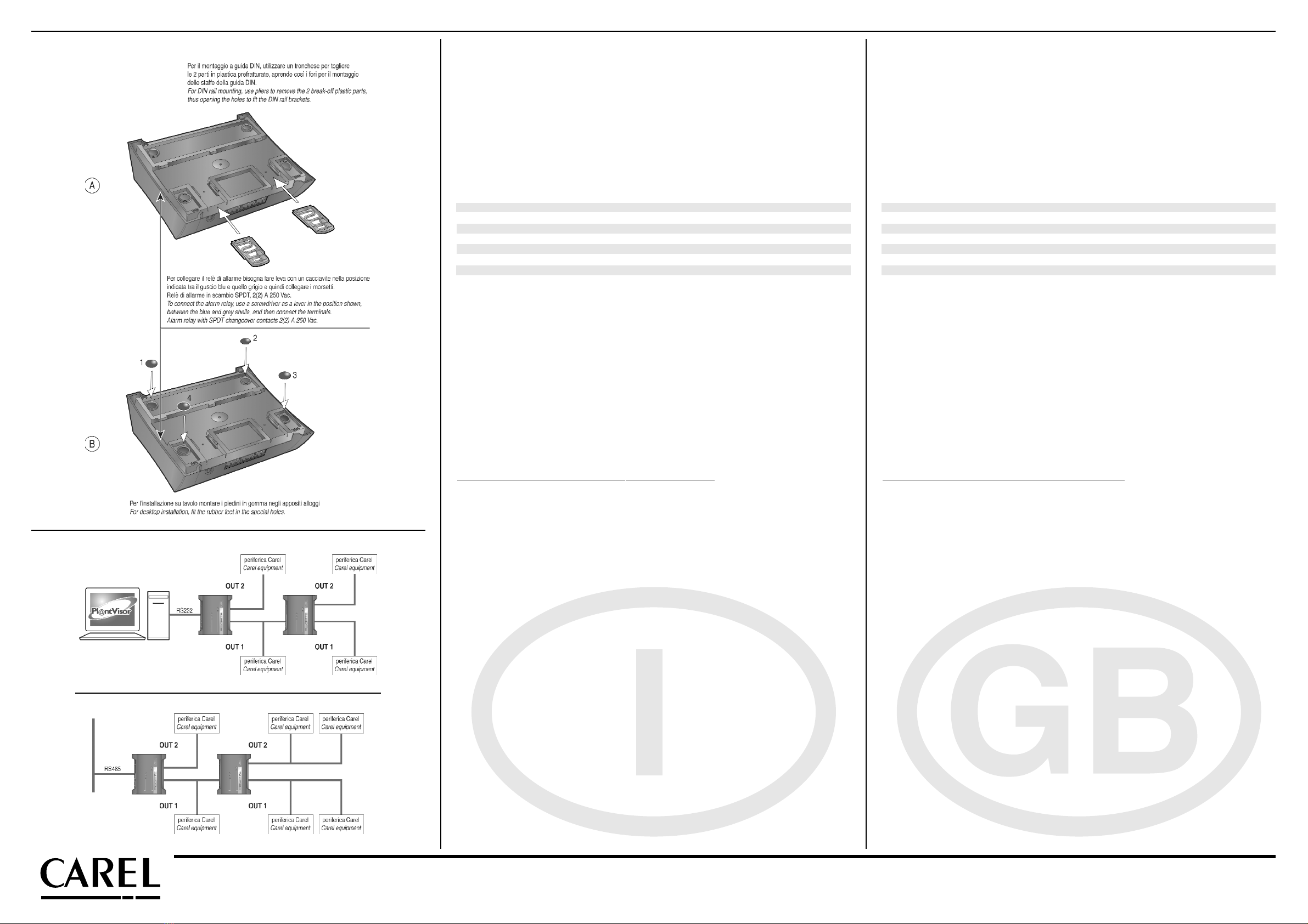
Cablaggio / Wiring
Fig. 4
Fig. 5
a) Montaggio a guida DIN; b) Installazione su tavolo / a) DIN rail mounting; b) Installation on table

This manual suits for next models

1

Other Carel Media Converter manuals

Carel EVDCNV00E0 User manual

Carel

Carel EVDCNV00E0 User manual

Carel VFD-NXL User manual

Carel

Carel VFD-NXL User manual

Carel CVSTD000 User manual

Carel

Carel CVSTD000 User manual

Carel CVSTDUMOR0 User manual

Carel

Carel CVSTDUMOR0 User manual

Popular Media Converter manuals by other brands

TRENDnet TFC-1000S10D3 Specifications

TRENDnet

TRENDnet TFC-1000S10D3 Specifications

LF Engineering SPL-2/75 AM-BC quick start guide

LF Engineering

LF Engineering SPL-2/75 AM-BC quick start guide

Cirrus Logic CS5530 manual

Cirrus Logic

Cirrus Logic CS5530 manual

Matrox Rapixo CL Pro Installation and Hardware Reference

Matrox

Matrox Rapixo CL Pro Installation and Hardware Reference

Vicon 262-00-06 installation guide

Vicon

Vicon 262-00-06 installation guide

Aputure A810 user manual

Aputure

Aputure A810 user manual

REXROTH VFC 3610 quick start guide

REXROTH

REXROTH VFC 3610 quick start guide

LEVTECH LSP-CRS422 user manual

LEVTECH

LEVTECH LSP-CRS422 user manual

Lynx C AD 5320 D Reference manual

Lynx

Lynx C AD 5320 D Reference manual

Yamaha UX96 owner's manual

Yamaha

Yamaha UX96 owner's manual

Assun AM-EN1611-S103 Series product manual

Assun

Assun AM-EN1611-S103 Series product manual

Siemens 7XV5662-0AC02 manual

Siemens

Siemens 7XV5662-0AC02 manual

Baumer HOG 100 Mounting and operating instructions

Baumer

Baumer HOG 100 Mounting and operating instructions

CommFront USB-232-1+TTL33-232-1 manual

CommFront

CommFront USB-232-1+TTL33-232-1 manual

e+p UHD 18 manual

e+p

e+p UHD 18 manual

Motorola SE-1010 product manual

Motorola

Motorola SE-1010 product manual

Elettronica Santerno SINUS PENTA Applications manual

Elettronica Santerno

Elettronica Santerno SINUS PENTA Applications manual

ADF Web HD67411 user manual

ADF Web

ADF Web HD67411 user manual

manuals.online logo
manuals.online logoBrands
  • About & Mission
  • Contact us
  • Privacy Policy
  • Terms and Conditions

Copyright 2025 Manuals.Online. All Rights Reserved.