Carillon Lumineux Melodys Flash Manual

1
Indoor Luminous Sounder
Carillon Lumineux pour intérieur
Instruction and operation manual
Manuel d’installation et d’utilisation
S’assurer à réception que le produit n’a pas été endommagé durant le transport pour réserve au transporteur.
Upon receipt, always check the product for damage during shipment. If any is found, you may le a damage claim with the carrier.
BODET SA
BP1
49340 TREMENTINES
Fax: 02.41.71.72.01
Usine de Trémentines
Système de
Management certifié
Réf : 607615 A
www.bodet-time.com
CARILLON LUMINEUX
MELODYS FLASH

2
Table of contents
1 - MECHANICAL INSTALLATION ...............................................................................................................................................3
2 - ELECTRICAL INSTALLATION ................................................................................................................................................4
2.1 - DIPS switches conguration .........................................................................................................................................4
2.2 - Commissioning ..............................................................................................................................................................4
3 - TECHNICAL CHARACTERISTICS ........................................................................................................................................5
Table des matières
1 - INSTALLATION MÉCANIQUE..................................................................................................................................................6
2 - INSTALLATION ÉLECTRIQUE.................................................................................................................................................7
2.1 - Conguration DIPS.........................................................................................................................................................7
2.2 - Mise en service..............................................................................................................................................................8
3 - CARACTÉRISTIQUES TECHNIQUES......................................................................................................................................8
SAFETY INSTRUCTIONS - PRECAUTIONS OF USE
The installation and the maintenance must be performed only by an authorized technician.
The «product » is powered by the mains. The installation must comply with the IEC 364 standard.
A readily accessible 10A max. two-pole circuit breaker must be installed in the supply line. This circuit breaker must switch off
the phase and neutral simultaneously.
The mains supply cable must be secured with a tie-wrap to prevent constraints on the terminals and to avoid possible short
circuit if a wire should come loose.
Warning: the mains cable must not be in contact with the mounting screw located right above the cable entrance. Use an
additional insulation sleeve on the L and N conductors.
See the various pictures illustrating the assembly
The product must be mounted on a wall or on a surface that must be at least 1cm wider than the product in order to limit the
access from the holes at the bottom of the casing.
CONSIGNES DE SECURITE - PRECAUTIONS D’UTILISATION
Intervention d’installation et de maintenance par une personne habilitée.
Le « produit » est raccordé à l’alimentation secteur 100-240 VAC. L’installation doit être conforme à la norme IEC 364 (NFC
15-100 pour la France).
Prévoir un disjoncteur maxi 10 A, rapidement accessible dans l’installation pour l’alimentation secteur. Le Disjoncteur doit
couper la phase et le neutre de manière simultanée.
Le câble secteur doit être xé à l’aide du collier de façon à ne pas exercer de contraintes sur les bornes de raccordement et pour
éviter une réduction de l’isolation dans le cas ou une des bornes viendrait à se desserrer.
Attention : le câble secteur ne doit pas pouvoir toucher la vis de xation située juste au dessus de l’entrée câble. Mettre la gaine
noire supplémentaire sur les conducteurs L et N s’ils ne sont pas gainés dans le produit.
Se reporter aux différentes photos illustrant le montage.
Le produit doit être xé sur un mur ou une surface dépassant d’au moins 1 cm tout autour du produit pour limiter l’accès par les
trous du fond du boitier

3
1 - MECHANICAL INSTALLATION
Choose the location where the Melodys Flash is to be installed according to the present of the power source nearby (the
power cable can be fed through the back of the product or through a knock-out on top of casing (use an electric drill and bit
to clean out the knock-out)).
1/Use a at blade screwdriver to remove the Melodys Flash front cover as shown on the following illustrations.
Attention: Use the scewdriver as a lever to pry the cover open but do not push the blade more than 1 cm inside the casing
so that the blade is resting on the back casing, not on the pc board.
2/ Remove the front cover carefully.
3/ Mount the Melodys Flash in its location using the 3 screws.
4/ Make sure that the Melodys Flash is resting well on the wall.
Warning: the product must not be powered on before it is mounted on the wall, the dips switches set and the front cover
put back in place.
70
44
130
12
Back casing - Rear view

4
2 - ELECTRICAL INSTALLATION
2.1 - DIP Switches Configuration
Once the Melodys Flash is mounted on the wall, make sure that the dip switches are set according
to your installation.
1st dip switches chip: «CONFIG»
- Switch 1 : let you set the ashing mode «Class» or «SEP», in case of manual control.
By default (factory conguration), the switces is set to OFF that is «Class».
- In «Class» mode, the light signal has a duration of 10 sec. split in 4 sequences according to the following cycle :
Leds ON (100ms) I Leds OFF (100ms) I Leds ON (1200ms) I Leds OFF (100ms).
- In«SEP» mode, lthe light signal has a duration of 30 ses split in 2 sequences according to the following cycle :
Leds ON (250ms) I Leds OFF(250ms).
- Switches 2 and 3 : let you set the light intensity :
Light intensity Switches position
Dip 2 Dip 3
100% on ↑ on ↑
75% on ↑ off ↓
50% off ↓ on ↑
25% off ↓ off ↓
By default (factory conguration) the switches 2 and 3 are set to ON and OFF respectively that is 75% intensity level.
Recommendations: favor a 100% light intensity level if Melodys Flash is installed in a well lit area an a 25% level if the Melodys
Flash is installed in a poorly lit area.
- Switches 4 and 5: not used.
2nd dip switches chip: «INIT/CIRCUIT N°»
- Dip switch 1: sets the Melodys Flash in INIT (initialisation) mode. in order to pair the Melodys Flash with a master clock (SIGMA). The
INIT mode is activated on a change of position of the dip switch.
By default (factory conguration), the dip switch 1 in on the OFF position.
- Dip switches 2, 3, 4 and 5: used to congurate the HF (High Frequency) reception of the Melodys Flash.
DHF Circuit n° Dip 2 Dip 3 Dip 4 Dip 5
60 off ↓ off ↓ off ↓ off ↓
61 off ↓ off ↓ off ↓ on ↑
62 off ↓ off ↓ on ↑ off ↓
63 off ↓ off ↓ on ↑ on ↑
64 off ↓ on ↑ off ↓ off ↓
65 off ↓ on ↑ off ↓ on ↑
66 off ↓ on ↑ on ↑ off ↓
67 off ↓ on ↑ on ↑ on ↑
68 on ↑ off ↓ off ↓ off ↓
69 on ↑ off ↓ off ↓ on ↑
70 on ↑ off ↓ on ↑ off ↓
71 on ↑ off ↓ on ↑ on ↑
72 on ↑ on ↑ off ↓ off ↓
73 on ↑ on ↑ off ↓ on ↑
74 on ↑ on ↑ on ↑ off ↓
75 on ↑ on ↑ on ↑ on ↑
A
B
AB
By default (factory conguration), the dip switches 2 to 5 are on
the OFF position (DHF circuit number 60).
The setting of the dip switches (see table) is identical to that of the
Melodys Sounder.

5
2.2 - Commissioning
1/ A black plastic girdle of Ø6mm is delivered in a plastic bag. Position this girdle as indicated on the photo to assure a double
electric insulation (sector) in case the drivers L and N are not sheathed.
2/ There are 2 ways toonnect the power cord (not supplied) to the
pc board of the Melodys Flash.
1st Method: 2nd method:
3/ To close Melodys Flash.t the top of the cover
over the back casing and apply pressure as shown
in the illustration below.
4/ Plug the power cord into the outlet.
Powering on the Melodys Flash:
When powered up for the first time the Melodys Flash is in the INIT mode (orange «Ψ» Led flashing).
Set the Sigma master clock in the INIT mode (see the master clock user manual). Once the Melodys is initialized the «Ψ» Led
turns red then green after the Melodys has received a DHF sounder control command from the master clock.
Nota: the DHF sounder control commands are sent every hour and every time a modification is made to the program. To set
the Melodys Flash in the INIT mode flip the DIP switch 1 while the Melodys Flash is in operation.
«Test» Button:
- pressing this button lets you test the operation of the Melodys Flash Leds (start an
stop the test). The flashing frequency varies according to the programmed fuction
«Class» or «SEP».
LED «~» : green led indicating that the Melodys Flash is powered up.
LED «Ψ» : green/orange/red led indicating the quality of the signal between the Melodys
Flash and the master clock:
- Green: communication ok.
- Fixed orange: the reception is unreliable.
- Flashing orange: Melodys in «Init» mode.
- Red: no program received.
After being powered up the product waits for a control command from the master clock.
3 - TECHNICAL CHARACTERISTICS
The Melodys Flash complies with the EMC directives 89/336/CEE and R&TTE 1999/5/CEE (residential, commercial or
industrial environments.
The Melodys Flash complies with the european standards:
EN 60950: safety of information technology equipment.
EN 301-489-3 (ElectroMagnetic Compatibility (EMC) standard for radio equipment and services).
EN 300-220-2 (Electromagnetic compatibility and Radio spectrum Matters (ERM)).
- Power supply : 100 to 240VAC ±10% 50/60 Hz.
- Consumption : 50mA in 230VAC.
- Luminosity : 60 candela/m².
- Electric insulation : class II.
- Connector of mains supply : N and L of 0,5² to 2,5².
- Entry of cables : 2x2,5² with girdle Ø10 mm maxi.
- Protection index : IP30 et IK02.
- Weight: 350 grs.
- Operating temperature: 0 to +50°C.
Cleaning:
- Use an antistatic product.
- Never use alcohol, acetone or other solvant that mau damage the casing.

6
1 - INSTALLATION MÉCANIQUE
Dénir l’emplacement du Melodys Flash en s’assurant de la proximité de l’alimentation (prévoir le passage du câble
d’alimentation au dos du produit ou la découpe du boîtier en partie haute à l’aide d’une perçeuse et d’un foret acier).
Ouvrir le boîtier du Melodys Flash, à l’aide d’un tournevis plat.
1/ Placer le tournevis dans l’espace prévu, situé sous le produit (1).
2/ Dégager le capot en faisant levier vers le haut en prenant appui sur la platine de xation (2).
1 2
Attention : ne pas enfoncer le tournevis plus de 1 cm dans la fente sous peine d’endommager la carte électronique.
3/ Ôtez délicatement la face avant.
4/ Fixer le Melodys Flash à son emplacement à l’aide des 3 vis de xation.
Platine de xation - vue arrière
5/ Veiller à ce que le Melodys Flash soit bien plaqué au mur.
Impératif : le matériel ne doit être mis sous tension qu’après xation, paramétrage des dips, et remontage de la face
avant.
70
44
130

7
2 - INSTALLATION ÉLECTRIQUE
2.1 - Configuration DIPS
Une fois le Melodys Flash xé au mur, s’assurer que la conguration des dips correspond à
votre installation.
1ère rangée de dips : «CONFIG»
- Dip 1 : permet de congurer le mode de ashage «Cours» ou «PPMS», en cas de commande manuelle.
Par défaut (conguration usine), le dip est à OFF soit de type «Cours».
- En mode «Cours», le signal lumineux est de 10s et décomposé en 4 phases selon le cycle suivant :
Leds allumées (100ms) I Leds éteintes (100ms) I Leds allumées (1200ms) I Leds éteintes (100ms).
- En mode «PPMS», le signal lumineux est de 30s et décomposé en 2 phases selon le cycle suivant :
Leds allumées (250ms) I Leds éteintes (250ms).
- Dips 2 et 3 : permettent de programmer la luminosité désirée :
Niveau d’éclairage Position des dips
Dip 2 Dip 3
100% on ↑ on ↑
75% on ↑ off ↓
50% off ↓ on ↑
25% off ↓ off ↓
Par défaut (conguration usine), les dips 2 et 3 sont respectivement à ON et OFF soit un niveau d’éclairage de 75%.
Recommandations : préférer un niveau d’éclairage de 100% si le Melodys Flash est exposé dans une zone éclairée. Dans le cas
contraire, programmer un niveau d’éclairage à 25% si le Melodys Flash est installé dans un endroit sombre.
- Dips 4 et 5 : inutilisés.
2ème rangée de dips : «INIT/N°CIRCUIT»
- Dip 1 : permet la mise en mode INIT (initialisation) du Melodys Flash. Ce mode permet de pouvoir appairer le Melodys Flash à une
horloge mère (SIGMA). L’activation du mode INIT s’effectue sur un changement d’état du dip.
Par défaut (conguration usine), le dip 1 est à OFF.
- Dip 2, 3, 4 et 5 : permettent de congurer la réception HF (Haute fréquence) du Melodys Flash.
N° Circuit DHF Dip 2 Dip 3 Dip 4 Dip 5
60 off ↓ off ↓ off ↓ off ↓
61 off ↓ off ↓ off ↓ on ↑
62 off ↓ off ↓ on ↑ off ↓
63 off ↓ off ↓ on ↑ on ↑
64 off ↓ on ↑ off ↓ off ↓
65 off ↓ on ↑ off ↓ on ↑
66 off ↓ on ↑ on ↑ off ↓
67 off ↓ on ↑ on ↑ on ↑
68 on ↑ off ↓ off ↓ off ↓
69 on ↑ off ↓ off ↓ on ↑
70 on ↑ off ↓ on ↑ off ↓
71 on ↑ off ↓ on ↑ on ↑
72 on ↑ on ↑ off ↓ off ↓
73 on ↑ on ↑ off ↓ on ↑
74 on ↑ on ↑ on ↑ off ↓
75 on ↑ on ↑ on ↑ on ↑
A
B
AB
Par défaut (conguration usine), les dips 2 à 5 sont à OFF
soit le numéro de circuit DHF 60.
La programmation des dips (tableau ci-contre) est identique au
Carillon Melodys.

8
2.2 - Mise en service
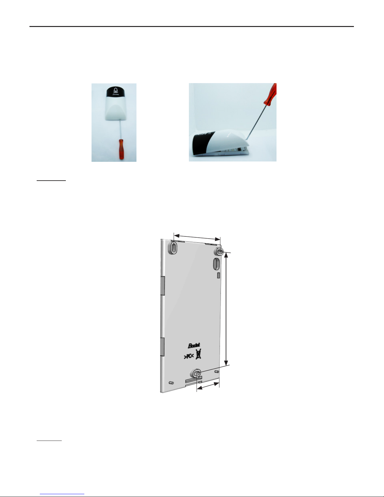
1/ Une gaine plastique noire de Ø6mm est livrée avec le produit. Elle permet d’assurer une double isolation secteur dans le
cas où les conducteurs L et N ne sont pas gainés dans le produit. Les ls L et N doivent être maintenu par le rislan comme
indiqué sur les photos.
2/ Brancher le câble d’alimentation (non fourni) sur la carte
électronique du Melodys Flash (2 possibilités).
1ère possibilité : 2ème possibilité :
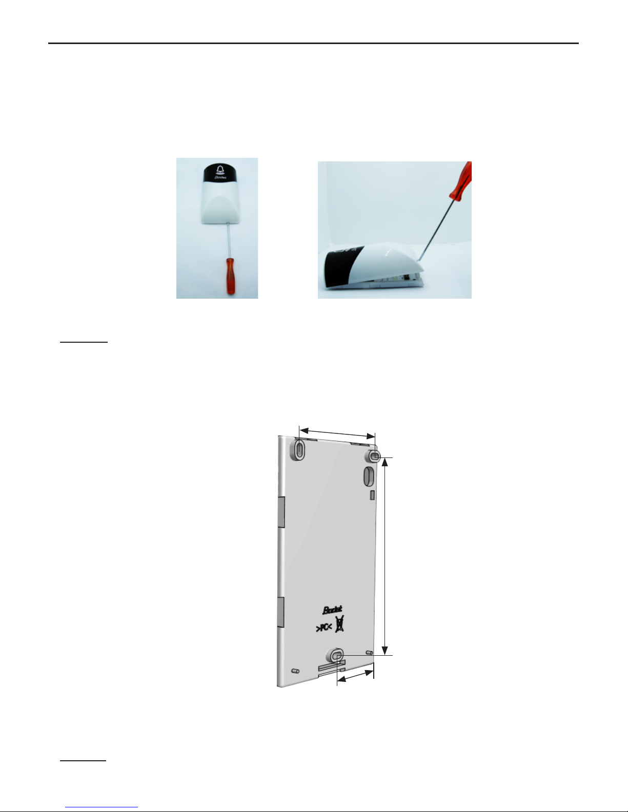
3/ Fermer le Melodys Flash. Emboîter la partie haute
du boîtier sur la platine. Refermer en exerçant une
pression sur la partie haute (dans le sens de la
èche ci-dessous).
4/ Brancher le câble d’alimentation sur une prise secteur.
Melodys Flash sous tension :
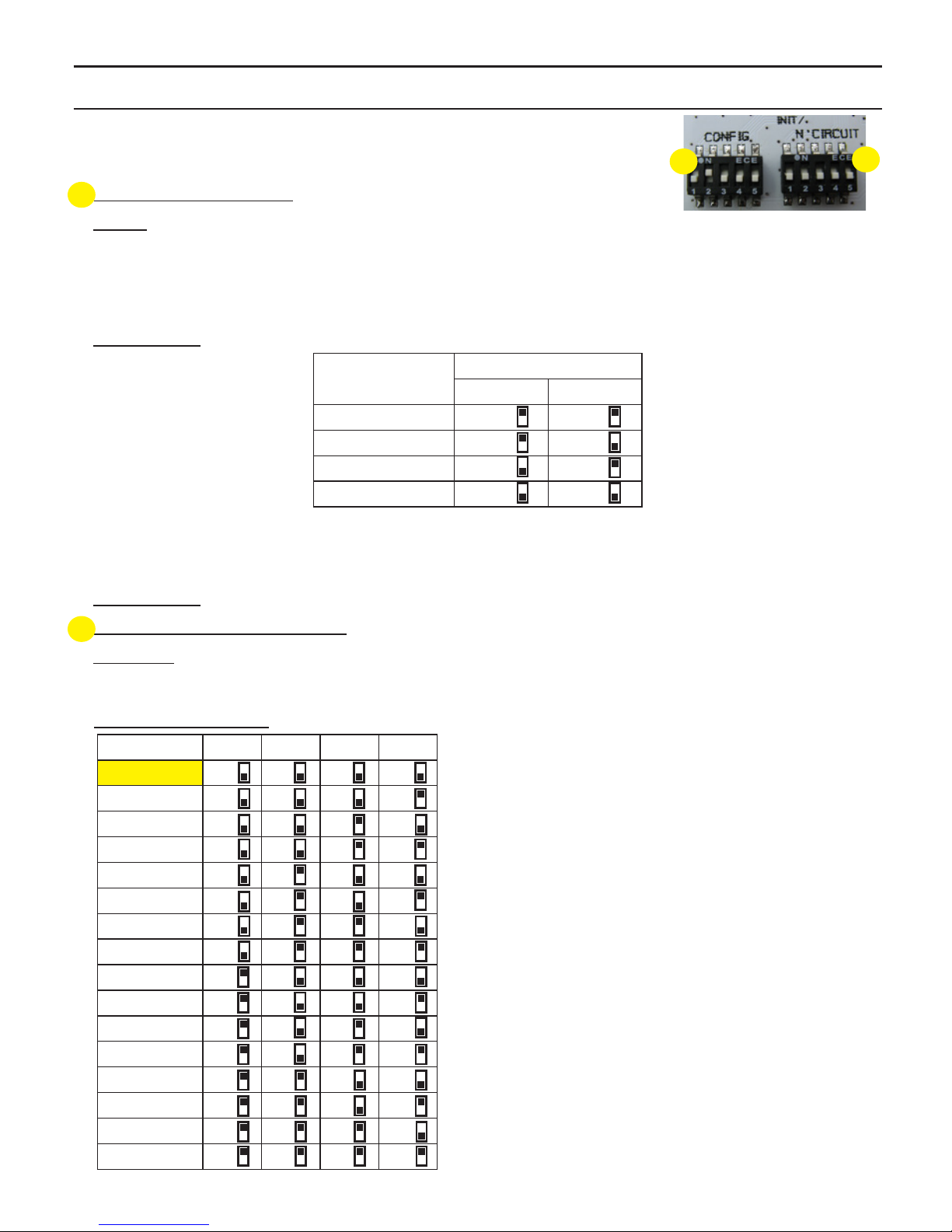
A la première mise en service, le Melodys Flash est en mode INIT (Led «Ψ» orange clignotante).
Mettre l’horloge mère Sigma en mode INIT (voir la notice de l’horloge mère). Une fois le récepteur initialisé, la Led «Ψ» est
alors rouge dans un premier temps puis verte après réception des commandes de carillons DHF de l’horloge mère. Nota
: les commandes de carillons DHF sont envoyées toutes les heures et à chaque modification de la programmation. Pour
remettre le Melodys Flash en mode INIT, il suffit d’effectuer un changement d’état au DIP 1 lorsque le Melodys Flash est en
fonctionnement.
Bouton «Test» :
- un appui permet de tester le fonctionnement des leds du Melodys Flash (lancement
et arrêt du mode test). La fréquence de flashage diffère en fonction du mode
programmé : «Cours» ou PPMS».
LED «~» : led verte pour indiquer la présence du secteur.
LED «Ψ» : led verte/orange/rouge pour indiquer la qualité du signal entre le Melodys
Flash et l’horloge mère :
- Led verte, la communication ok.
- Led orange fixe, le Melodys est en limite de zone de réception, la réception est
aléatoire.
- Led orange clignotante, le Melodys est en mode «Init».
- Led rouge, pas de programme reçu.
Après la mise sous tension du produit, celui-ci attend un ordre d’exécution venant de l’horloge mère.
3 - CARACTÉRISTIQUES TECHNIQUES
Le Melodys Flash respecte la directive compatibilité électromagnétique 89/336/CEE et la Directive R&TTE 1999/5/CEE.
Ils sont destinés à un environnement résidentiel, commercial ou industriel.
Ils sont conformes aux normes européennes : EN 60950 : Sécurité des Appareils de Traitement de l’Information. EN 301-
489-3 (CEM des produits radio : émission et immunité). EN 300-220-2 (bonne utilisation du spectre radio).
- Alimentation : 100 à 240VAC ±10% 50/60 Hz.
- Consommation : 50mA à 230VAC.
- Luminosité : 60 candela/m².
- Isolation électrique : classe II.
- Connecteur d’alimentation secteur : 2 bornes N et L de 0,5² à 2,5².
- Dimensions de l’entrée des câbles : orice pour câble de 2x2,5² avec gaine Ø 10 mm maxi.
- Indice de protection : IP30 et IK02.
- Poids : 350 grs.
- Température de fonctionnement : 0 à +50°C.
Nettoyage :
- Utiliser un produit antistatique.
- Ne jamais utiliser d’alcool, d’acétone ou autres solvants susceptibles d’endommager le boîtier.
Table of contents
Languages: