FHF AVISA AX03 User manual

Sounder
AX03
FHF BA 6030-10 04/11
AX03
Installation
Th sound r can b affix d to most surfac s using
scr ws through th xt rnal mounting lugs. A 20 mm
gland ntry is provid d for th supply cabl . Th cabl
and gland must b fitt d in accordanc with th national
and local r gulations. It is not n c ssary to arth th
sound r circuitry but arth tags should b us d if arth
continuity of conduit or cabl sh athing n ds to b
maintain d.
Supply input
Ensur that th supply is corr ct for th voltag rating of
th sound r. Ensur that th supply is OFF b for
making any conn ction and wir only in accordanc
with th t rminal lab l d tail.
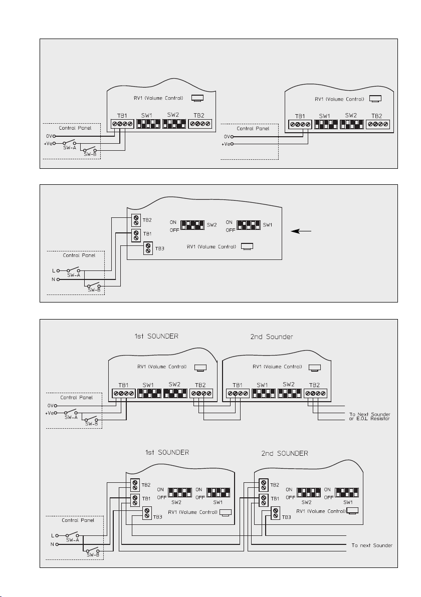
Sound selection
Ensur th supply is OFF b for proc ding. All dc and
ac units hav s l ctabl alarm sounds (s tabl b low
for d tails) and ar s l ctabl by m ans of th 5 way
DIL switch s SW1 for th first stag and SW2 for th
s cond stag . For dc units th s cond sound is mad
availabl upon th application of a third wir conn ct d
to t rminal TB 1/3 as shown in Fig. 1 whil still conn c-
t d to t rminal TB 1/2. Alt rnativ ly first and s cond sta-
g sound signals can b g n rat d by supply r v rsal at
t rminals TB1/3 and TB1/4, s Fig. 2. For ac units th
s cond stag is availabl upon th application of a third
wir L to TB3, s Fig. 3.
Mounting
Th AX03 s ri s alarm units ar mount d to a wall or
bulkh ad of suitabl mat rial using th lugs proj cting
from th sid of th cas . Th lugs ar bor d 6 mm cl -
aranc on 102 mm c ntr s. Th r comm nd d l ngth
of fixing scr ws is 20 mm. To maintain th int grity of
th w ath r s al, th cabl ntry must b via a suitabl
s al d gland.
Recycling
Th d vic may b compl t ly r cycl d as l ctronic
wast . Wh n th d vic is disass mbl d, plastics,
m tals and l ctronics ar to b dispos d of s parat ly.
Th d vic compli s with th r quir m nts of th
n w EMC-dir ctiv 2004/108/EC and th low voltag
dir ctiv 2006/95/EC.
Th conformity with th abov dir ctiv s is confirm d
by th CE sign.
EMC-Directive
Dimensions AX03
102
89
3
89
ø 6
118
85
8

2
Sound selection table
1 Alt rnat two-ton 800 - 1000 0.5 1 1 1 1 1 Fir Alarms
2 Alt rnat two-ton 2500 - 3100 0.5 0 1 1 1 1 S curity Alarms
3 Alt rnat fast two-ton 800 - 1000 0.25 1 0 1 1 1 Incr as d urg ncy
4 Alt rnat fast two-ton 2500 - 3100 0.25 0 0 1 1 1 S curity d t rr nt
5 Alt rnat two-ton 440 - 554 0.4/0.1 1 1 0 1 1 AFNOR, Franc
6 Alt rnat two-ton 430 - 470 1.0 0 1 0 1 1
7 Alt rnat v. fast two-ton 800 - 1000 0.13 1 0 0 1 1
8 Alt rnat v. fast two-ton 2500 - 3200 0.07 0 0 0 1 1
9 Alt rnat two-ton 440 - 554 2.0 1 1 1 0 1 Turn-out, Sw d n
10 Continuous ton 700 - 0 1 1 0 1 All-cl ar, Sw d n
11 Continuous ton 1000 - 1 0 1 0 1
12 Continuous ton 1000 - 0 0 1 0 1
13 Continuous ton 2300 - 1 1 0 0 1
14 Continuous ton 440 - 0 1 0 01
15 Int rrupt d ton 1000 2.0 1 0 0 0 1
16 Int rrupt d ton 420 1.25 0 0 0 0 1 AS2220, Australia
17 Int rrupt d ton 1000 0.5 1 1 1 1 0
18 Int rrupt d ton 2500 0.25 0 1 1 1 0
19 Int rrupt d ton 2500 0.5 1 0 1 1 0
20 Int rrupt d ton 700 6/12 0 0 1 1 0 Pr -vital m ss, Sw d n
21 Int rrupt d ton 1000 1.0 1 1 0 1 0
22 Int rrupt d ton 700 4.0 0 1 0 1 0 Air-raid, Sw d n
23 Int rrupt d ton 700 0.25 1 0 0 1 0 Local warning, Sw d n
24 Int rrupt d ton 720 0.7/0.3 0 0 0 1 0 Industrial alarm, G rmany
25 Int. fast rising volum 1400 0.25 1 1 1 0 0
26 Fast sir n 250 - 1200 0.085 0 1 1 0 0
27 Rising constant, fall 1000 10/40/10 1 0 1 0 0 Industrial alarm, G rmany
28 ISO 8201 Evacuation 800 - 1000 as std 0 0 1 0 0 Int. vacuation alarm
29 Fast whoop 500 - 1000 0.15 1 1 0 0 0
30 Slow whoop 500 - 1200 4.5 0 1 0 0 0 Evacuation, Th N th rlands
31 R v rs sw ap 1200 - 500 1 1 0 0 0 0 Evacuation, G rmany
32 Sir n 500 - 1200 3.0 0 0 0 0 0
Switch s ttings: ON=1 und OFF=0
First and Second Stage Fre uency / Rept. Switches Special
Hz rate 1 2 3 4 5 Application
The PFEER sound signals recommended by UKOOA are:
G n ral Alarm Sound signal 15 Int rrupt d ton 1000 Hz
PAPA Sound Signal 31 R v rs Sw p 1200-500 Hz
Toxic Gas Sound Signal 11 Continuous Ton 1000 Hz
Warning:
Loud alarm sound. Wear ear defenders when testing,
installing and commissioning.
Housing Polycarbonat
Colour R d, similar to RAL 2002
Insulation class II
Prot ction d gr IP 65 acc. to IEC 60529
Cabl gland int nd d for M20 x 1.5 or S lf-s aling gromm t
Volum approx. 97-110 dB(A) (d p nding on signal ton )
Signals 32 diff r nt signal ton s, s diagrams
2nd stag can b turn d on xt rnally
Tmp ratur rang
Op ration -25 °C to +55 °C
Storag -40 °C to +70 °C
Wight AC 0.4 kg / DC 0.3 kg
Op rating voltag 24 VDC, 115 VAC, 230 VAC
Conn cting t rminals Clamping capacity 2.5 mm2solid conductor / 1.5 mm2strand d conductor
Technical Data
3
DC Input - second stage with third wire
Lin int grity: monitor via r v rs polarity
DC Input - second stage by supply reversal
Lin int grity: monitor via thr shold (appli d voltag ≤ 1 V)
An nd-of-lin (E.O.L) r sistor is r quir d for lin monitoring and
it should b a minimum r sistanc of 3K3 ohms and 0.5 watts.
AC Input
System connection
SOUND SELECTION
Figure 1
Figure 3
Figure 4
Figure 2

FHF Funk + Hust r F rnsig GmbH
G w rb all 15-19 · D-45478 Mülh im an d r Ruhr
Phon +49 / 208 / 82 68-0 · Fax +49 / 208 / 82 68-286
User information
1. Th applianc has b n d sign d for insulation class II and is only to b conn ct d to, and op rat d with, th sp cifi d
voltag . Sp cifications of polarity must b obs rv d.
2. Ensur that th casing is not damag d.
3. Th r l vant cod s of Practic an Trad Association r quir m nts for sav op ration must b obs rv d.
4. Liv compon nts may b com xpos d wh n cov rs ar op n d or parts ar r mov d. B for op ning th applianc
for alignm nt, maint nanc , r pair or r plac m nt of parts, th applianc must b disconn ct d from all pow r sup-
pli s. If it is n c ssary to carry out alignm nt, maint nanc or r pair on th op n and liv d vic , this is only to b
und rtak n by a qualifi d sp cialist who has r c iv d corr s ponding instruction.
5. Capacitors may still b in a charg d stat v n aft r th applianc has b n disconn ct d from all pow r suppli s.
6. Th applianc is only to b op rat d und r th sp cifi d ambi nt conditions and in th sp cifi d mod of op ration.
Unfavou rabl ambi nt conditions may caus damag to th applianc and put th us r’s lif at risk. Unfavou rabl
ambi nt conditions may b :
• xc ssiv air humidity (>75%, r lativ , cond nsing)
• moistur , dust (obs rv prot ction class)
• flammabl gas s, vapours, solv nts
• xc ssiv ly high ambi nt t mp ratur s (>55°C)
7. Th ambi nt t mp ratur s must b within th sp cifi d rang .
8. Th applianc is d sign d for both indoor and outdoor us .
9. Th installation and commissioning of th applianc may only b carri d out by a qua lifi d sp cialist; th sam appli s
to any r pairs with original spar parts. Th us of oth r than original spar parts may caus damag or injury.
Subj ct to alt rations or rrors
Other FHF Marine Equipment manuals


