Carlisle Fluid Technologies Ransburg IntelliFlow RM2 User manual

EN
www.carlisleft.com Manual 77-3153-R1 (03/2022)
CONTROLS MANUAL
IntelliFlow RM2

EN
www.carlisleft.com Manual 77-3153-R1 (03/2022)
2
CONTENTS
SAFETY....................................................................................................................... 4
SAFETY PRECAUTIONS.................................................................................................................. 4
EU DECLARATION OF CONFORMITY.......................................................................................... 9
INTRODUCTION ........................................................................................................ 11
FEATURES ........................................................................................................................................ 11
SYSTEM COMPONENTS.................................................................................................................. 12
COMPLETE SYSTEM PART NUMBERING ..................................................................................... 14
TECHNICAL SPECIFICATIONS ...................................................................................................... 14
WALL MOUNT DIMENSIONS ......................................................................................................... 15
FLOOR STAND DIMENSIONS (OPTIONAL)................................................................................. 16
INSTALLATION.......................................................................................................... 17
ELECTRICAL..................................................................................................................................... 17
PNEUMATICS.................................................................................................................................... 18
PAINT MATERIALS .......................................................................................................................... 21
DISPOSAL INFORMATION ............................................................................................................. 22
OPERATION ............................................................................................................... 23
POWERING UP THE SYSTEM......................................................................................................... 23
USER INTERFACE GUIDE ............................................................................................................... 23
STARTUP GUIDE .............................................................................................................................. 40
DAILY OPERATIONS....................................................................................................................... 42
B PUMP OPERATION....................................................................................................................... 46
FLOW METER................................................................................................................................... 47
MAINTENANCE, TROUBLESHOOTING & SPARE PARTS..................................... 49
ALARM TROUBLESHOOTING ........................................................................................................ 49
B PUMP TROUBLESHOOTING ....................................................................................................... 52
POWER OUTAGE CLEANING PROCEDURE ................................................................................ 53
FLOW METER TROUBLESHOOTING ............................................................................................ 54
MAINTENANCE PROCEDURES...................................................................................................... 55
PREVENTIVE MAINTENANCE........................................................................................................ 56
CONTENTS

EN
www.carlisleft.com Manual 77-3153-R1 (03/2022)
3
CONTENTS
REGULAR INSPECTION .................................................................................................................. 57
COMPONENT VIEWS & SPARE PARTS ........................................................................................ 58
ELECTRICAL DIAGRAMS................................................................................................................ 62
MANUAL CHANGE SUMMARY ................................................................................ 86
WARRANTY POLICY ................................................................................................ 87

EN
www.carlisleft.com Manual 77-3153-R1 (03/2022)
4
SAFETY
SAFETY
SAFETY PRECAUTIONS
Before operating, maintaining or servicing any Carlisle
system, read and understand all of the technical and
safety literature for your products. This manual contains
information that is important for you to know and
understand. This information relates to USER SAFETY and
PREVENTING EQUIPMENT PROBLEMS.
To help you recognize this information, we use the
following symbols. Please pay particular attention to
these sections.
WARNING
A WARNING! states information to alert you to a situation
that might cause serious injury if instructions are not
followed.
WARNING
The user MUST read and be familiar with the Safety
Section in this manual and the Ransburg safety literature
therein identified.
This equipment is intended to be used by trained
personnel ONLY.
This manual MUST be read and thoroughly understood by
ALL personnel who operate, clean or maintain this
equipment! Special care should be taken to ensure that
the WARNINGS and safety requirements for operating
and servicing the equipment are followed. The user
should be aware of and adhere to ALL local building and
fire codes and ordinances as well as any applicable
country safety standards, prior to installing, operating,
and/or servicing this equipment.
WARNING
The hazards shown on the following pages may occur
during the normal use of this equipment.
CAUTION
A CAUTION! states information that tells how to prevent
damage to equipment or how to avoid a situation that
might cause minor injury.
NOTE
A NOTE is information which is relevant to the procedure
in progress.
While this manual lists standard specifications and service
procedures, some minor deviations may be found
between this literature and your equipment. Differences
in local codes and plant requirements, material delivery
requirements, etc., make such variations inevitable.
Compare this manual with your system installation
drawings and appropriate equipment manuals to
reconcile such differences.

EN
www.carlisleft.com Manual 77-3153-R1 (03/2022)
5
SAFETY
It is the of the to this to the of the
Read the following warnings before using this equipment
WARNING
STATIC CHARGE Fluid may develop a static charge that
must be dissipated through proper grounding of the
equipment, objects to be sprayed and all other electrically
conductive objects in the dispensing area. Improper
grounding or sparks can cause a hazardous condition and
result in fire, explosion or electric shock and other serious
injury.
AUTOMATIC EQUIPMENT Automatic equipment may start
suddenly without warning.
WEAR RESPIRATOR Toxic fumes can cause serious injury
or death if inhaled. Wear a respirator as recommended by
the fluid and solvent manufacturer’s Safety Data Sheet.
TOXIC FLUID & FUMES Hazardous fluid or toxic fumes can
cause serious injury or death if splashed in the eyes or on
the skin, inhaled, injected or swallowed. LEARN and KNOW
the specific hazards or the fluids you are using.
INSPECT THE EQUIPMENT DAILY Inspect the equipment
for worn or broken parts on a daily basis. Do not operate
the equipment if you are uncertain about its condition.
KEEP EQUIPMENT GUARDS IN PLACE Do not operate the
equipment if the safety devices have been removed.
KNOW WHERE AND HOW TO SHUT OFF THE
EQUIPMENT IN CASE OF AN EMERGENCY
WEAR SAFETY GLASSES Failure to wear safety glasses
with side shields could result in serious eye injury or
blindness.
FIRE AND EXPLOSION HAZARD Improper equipment
grounding, poor ventilation, open flame or sparks can cause
a hazardous condition and result in fire or explosion and
serious injury.
MEDICAL ALERT Any injury caused by high pressure liquid
can be serious. If you are injured or even suspect an injury:
• Go to an emergency room immediately.
• Tell the doctor you suspect an injection injury.
• Show the doctor this medical information or the
medical alert card provided with your airless spray
equipment.
• Tell the doctor what kind of fluid you were spraying or
dispensing.
• Refer to the Material Safety Data Sheet for specific
information.
NEVER MODIFY THE EQUIPMENT Do not modify the
equipment unless the manufacturer provides written
approval.
GET IMMEDIATE MEDICAL ATTENTION To prevent contact
with the fluid, please note the following:
• Never point the gun/valve at anyone or any part of the
body.
• Never put hand or fingers over the spray tip.
• Never attempt to stop or deflect fluid leaks with your
hand, body, glove or rag.
• Always have the tip guard on the spray gun before
spraying.
• Always ensure that the gun trigger safety operates
before spraying.
• Always lock the gun trigger safety when you stop
spraying.
NOISE HAZARD You may be injured by loud noise.
Hearing protection may be required when using this
equipment.
PROJECTILE HAZARD You may be injured by venting
liquids or gases that are released under pressure, or flying
debris.
PROP 65 WARNING: This product contains chemicals
known to the State of California to cause cancer and birth
defects or other reproductive harm.
READ THE MANUAL: Understand how to operate and
service the equipment before performing these actions.
GROUND EQUIPMENT: The symbol denotes a connection
point for ground.
ELECTRICAL SHOCK: Hazardous electrical energy is
present inside the main control enclosure. Use caution if
performing tasks within the cabinet.
PINCH HAZARD: Moving equipment could cause injury to
fingers or hands.
LOCK-OUT-TAG-OUT: Before performing any
maintenance on the equipment, lock-out the main
electrical disconnect.

EN
www.carlisleft.com Manual 77-3153-R1 (03/2022)
6
AREA
Tells where hazards
may occur
HAZARD
Tells what the hazard is
SAFEGUARDS
Tells how to avoid the hazard
Toxic
Substances
ISOCYANATE Conditions Spraying or dispensing fluids that contain isocyanates
creates potentially harmful mists, vapors, and atomized
particulates. Workers exposed to isocyanates can
develop a range of short and long-term health problems.
Read and understand the fluid manufacturer’s warnings
and Safety Data Sheet (SDS) to know specific hazards
and precautions related to isocyanates.
Use of isocyanates involves potentially hazardous
procedures. Do not spray with this equipment unless you
are trained, qualified, and have read and understood the
information in this manual and in the fluid manufacturer’s
application instructions and SDS.
Use of incorrectly maintained or mis-adjusted equipment
may result in improperly cured material which could
cause off-gassing and offensive odors. Equipment must
be carefully maintained and operated according to
instructions in the manual.
To prevent inhalation of isocyanate mists, vapors and
atomized particulates, everyone in the work area must
wear appropriate respiratory protection. Always wear a
properly fitting respirator, which may include a supplied-
air respirator. Ventilate the work area according to
instructions in the fluid manufacturer’s SDS.
Avoid all skin contact with isocyanates. Everyone in the
work area must wear chemically impermeable gloves,
protective clothing and foot coverings as recommended
by the fluid manufacturer and local regulatory authority.
Follow all fluid manufacturer recommendations, including
those regarding handling of contaminated clothing. After
spraying, wash hands and face before eating or drinking.
Hazard from exposure to isocyanates continues after
spraying. Anyone without appropriate personal
protective equipment must stay out of the work area
during application and after application for the time
period specified by the fluid manufacturer. Generally this
time period is at least 24 hours.
Warn others who may enter work area of hazard from
exposure to isocyanates. Follow the recommendations of
the fluid manufacturer and local regulatory authority.
Posting a sign outside the work area is recommended.
SAFETY

EN
www.carlisleft.com Manual 77-3153-R1 (03/2022)
7
AREA
Tells where hazards
may occur
HAZARD
Tells what the hazard is
SAFEGUARDS
Tells how to avoid the hazard
Toxic
Substances
Chemical Hazard
Certain materials may be harmful if
inhaled, or if there is contact with the
skin.
Follow the requirements of the Safety Data Sheet
supplied by coating material manufacturer.
Adequate exhaust must be provided to keep the air free
of accumulations of toxic materials.
Use a mask or respirator whenever there is a chance of
inhaling sprayed materials. The mask must be compatible
with the material being sprayed and its concentration.
Equipment must be as prescribed by an industrial
hygienist or safety expert, and be NIOSH approved.
Spray Area Explosion Hazard —
Incompatible Materials
Halogenated hydrocarbon solvents for
example: methylene chloride and 1,1,1, -
Trichloroethane are not chemically
compatible with the aluminum that
might be used in many system
components.
The chemical reaction caused by these
solvents reacting with aluminum can
become violent and lead to an
equipment explosion.
Spray applicators require that aluminum inlet fittings be
replaced with stainless steel.
Aluminum is widely used in other spray application
equipment - such as material pumps, regulators,
triggering valves, etc. Halogenated hydrocarbon solvents
must never be used with aluminum equipment during
spraying, flushing, or cleaning. Read the label or data
sheet for the material you intend to spray. If in doubt as
to whether or not a coating or cleaning material is
compatible, contact your coating supplier. Any other
type of solvent may be used with aluminum equipment.
SAFETY

EN
www.carlisleft.com Manual 77-3153-R1 (03/2022)
8
SAFETY
Additional Safety Information
The RM2 has a main operator panel emergency stop (E-Stop) pushbutton. Included with the unit.
In the event of a safety fault, all operations for the RM2 will halt, all solenoid outputs will be turned off, and all pressure
pilot signals will go to zero psi/BAR. Recovery from this state requires the user to reload material to reset all solenoids,
etc. before resuming operation.
CAUTION
Do not operate the RM2 before reading this section.
WARNING
Do not contact, disconnect, or other manipulation of electrical connections or devices while the system is under
power. The main disconnect on the right side of the controller can be locked out, and proper Lockout – Tagout
(LOTO) procedures should be used for any electrical work internal to the controller. If this is not possible for the
purpose of diagnosis and troubleshooting under working conditions, then only qualified electrical personnel should
perform the work.
NOTE
During initial commissioning of the equipment, and at periodic times throughout the life of the equipment, all fluid
fittings should be visually inspected for leaks. Periodically, all pieces of this equipment should be visually inspected
for signs of obvious degradation due to chemicals or other conditions that may be present in the environment where
the equipment is installed.
WARNING
Local regulations may require fire-suppression equipment to be installed where the equipment is operated.
WARNING
To avoid possible chemical spillage when no personnel are on site, air and fluid supplies for the equipment should be
Optionally, some sensors, switches, or other ancillary equipment, connected to this equipment may be located in the
presence of flammable gases and vapors. Any such equipment will be connected through the use of intrinsic-safe or
Zener barriers and will be classified as a ‘simple apparatus’ or be themselves approved to be used in such areas.

EN
www.carlisleft.com Manual 77-3153-R1 (03/2022)
9
EU DECLARATION OF CONFORMITY

EN
www.carlisleft.com Manual 77-3153-R1 (03/2022)
10
Page intentionally left blank

EN
www.carlisleft.com Manual 77-3153-R1 (03/2022)
11
INTRODUCTION
INTRODUCTION
The RM2 system is designed to accurately mix most two component (2K) and one component (1K) paints. It will
supply any low-pressure manual or automatic spray gun and can easily handle very low flow rates or high ratio
materials (greater than 20:1). The system uses real-time metering to accurately dispense and mix the resin and
hardener on-ratio regardless of varying flow rate as seen in real world paint applications such as feathering or rapid
triggering with manual guns.
The system is easily set up and operated with a 10” touch screen. Access to system parameters and usage data is
restricted via password protection.
RM2 systems are configurable with many options and accessories:
• Up to 7 paint colors
• One hardener flow sensor
• Gun flush boxes
• Pedestal Stand
• Stack light (Included)
• Atomizing air cut-off (Included)
• 2nd gun capability (Included)
See section 14.0 in this manual for information on accessory equipment.
FEATURES
The RM2 System has unique features that provide superior benefits:
Continuous Flow—The mix manifold is designed to optimize mix quality and minimize internal volume by receiving
Resin (Component A) and Hardener (Component B) continuously.
Accurate Dispensing—Control and positioning of the B metering pump is precise. An electronically controlled stepper
motor with integral linear actuator allow for dispense from 2cc to 600cc per minute, and ratios from 1:1 to 100:1
depending on the pump size chosen. Ratio tolerance down to 1% is possible.
Ease of Use—The touchscreen user interface is easy to learn and efficient to use. It provides control of the system with
few actions, along with real-time data and in-depth troubleshooting when alarms occur.
Easily Configurable— Use up to seven different paint resins and up to two spray guns. Flush boxes, atomizing air
control, and other options and accessories can be added at any time.
Programmable Flushing— Set unique flushing options specific to material needs.
Mounting Options—The system can be mounted to a wall and plumbed into an existing workspace, or it can be bolted
to the floor with an available pedestal stand.
Alarm Warnings—The alarm system warns the user of system errors and suggests possible solutions. Help screens
provide troubleshooting information to remedy system alarms.
Modular Design—Sub-assemblies are easily and quickly removed for maintenance and repair.

EN
www.carlisleft.com Manual 77-3153-R1 (03/2022)
12
SYSTEM COMPONENTS
1. Control Panel
2. Fluid Control Module
3. Mix Manifold
4. Pedestal (Optional) 1
2
3
Control Panel
External Components
1. Status light
2. Main power entry
3. Main power disconnect switch
4. Panel opening latch
5. Emergency stop button
6. HMI
1
2
3
4
5
6
4
INTRODUCTION

EN
www.carlisleft.com Manual 77-3153-R1 (03/2022)
13
Internal Components
1. Solenoid stack
2. USB flash drive
3. Linear actuator
4. Air flow switches
5. Main power disconnect switch connector
6. Connection to status light
7. Connection to HMI and emergency stop
button
8. HMI (Internal)
9. IO block
10. 24VDC circuit breakers
11. 24VDC power supply
12. Main power circuit breaker
1
Fluid Control Module
1. Solvent flush valve
2. Solvent input connection
3. Air input connection
4. Air push valve
5. Component A input connection (x1)
6. Connection to solenoids (x1)
7. Fluid valves (x1)
8. Component A flow meter
9. Connection to mix module
10. Component B pump
11. Component B input connection
12. Component B output (to mix manifold)
Mix Manifold
13. Mix block
14. Static mix tube
15. 2-gun manifold (optional)
16. Connection to gun (x1)
2
3
4
5
6
7
8
9
10
11
12
15
14
13
INTRODUCTION
1
2
7
8
3
4
5
6910 11 12
16

EN
www.carlisleft.com Manual 77-3153-R1 (03/2022)
14
INTRODUCTION
COMPLETE SYSTEM PART NUMBERING
TECHNICAL SPECIFICATIONS
Pressure
1= 300 PSI
2= 3,000 PSI
RM2 ####
Compatibility
1= Standard
2= Acid
Flowmeter
0= None
1= Gear
2= Coriolis
#
Item Details
Max working air pressure 105 psi (7.2 bar)
Optimal working air pressure 75—105 psi (5.2—7.2 bar)
Max inlet fluid pressure 250 psi (17.2 bar)
Max B pump flow rate 10.1 or 20.3 oz/min (300 or 600 cc/m)
Min B pump flow rate 0.07 or 0.7 oz/min (2 or 20 cc/min)
“A” side flowmeter range 1.3—64 oz/min (10—1900 cc/min)
Operating temperature range 40—104° F (5—40° C)
System weight 130—150 lbs. (59—68 kg)
Viscosity range of fluid 20—3000 cPs
Mixing ratio range 1:1—100:1
Ratio tolerance range Up to ± 1%
Wetted parts 300 series stainless steel, PTFE, perfluoroelastomer, UHMW polyethylene
External power requirements 100—240 VAC, 50—60Hz. 2.45A/1.55A, 16 AWG power supply wire gauge; NOTE:
Environmental Indoor use, pollution degree (2)
Installation category II
Max altitude 6500 ft (2000m)
Humidity 80% rH up to 88° F (31° C); decreasing linearly to 50% rH @ 104° F (40° C); max 80%
rH non-condensing
Dispensing
1= 600 CC
2= 300 CC
5= Pulse
# of Colors
0= No color stack
1= 1 Color
3= 3 Colors
7= 7 Colors

EN
www.carlisleft.com Manual 77-3153-R1 (03/2022)
15
INTRODUCTION
WALL MOUNT DIMENSIONS
Requirements:
• Ensure wall is able to support weight of complete system, including air and fluid hoses and other connected
devices. Minimum 91 kg (200 lbs.).
• Ensure clearance for electrical and fluid connections to system, and door swing radius.
• Bolt RM2’s mast to wall or panel using minimum 4 each of 3/8” lag screws or cap screws with flat washers.

EN
www.carlisleft.com Manual 77-3153-R1 (03/2022)
16
INTRODUCTION
FLOOR STAND DIMENSIONS (OPTIONAL)
Requirements:
• Stand should be bolted to the floor.

EN
www.carlisleft.com Manual 77-3153-R1 (03/2022)
17
INSTALLATION
INSTALLATION
Before operating the RM2, ensure all the below installation steps are complete. Schematics and further information are
provided separately from this manual.
ELECTRICAL
The RM2 can accept either 120VAC or 240VAC as a power source. Its internal 24VDC power supply automatically
detects the input voltage and produces control power accordingly.
Main power entry to the cabinet is located at the top right-hand side of the cabinet. It accepts a universal socket as a
power connection.
WARNING
Before making electrical, air, and fluid connections to the RM2, be sure to understand and verify all requirements for
installation, including but not limited to: electrical codes, OSHA requirements, NFPA requirements, and all applicable
local codes and ordinances.
Read and understand all operating manuals for connected equipment. Do not supply RM2 with higher fluid or air
NOTE
Any conductive parts within 2.5m of this equipment (ladders, rails, fences, etc.) shall be bonded appropriately to
ground.
WARNING
Control enclosure cannot be placed in a hazardous location. Do not use equipment not approved for hazardous
locations. Do not modify system equipment.
WARNING
To maintain non-hazardous classification of this equipment, the dispense pump and fluid panel components and
assemblies must be monitored for leaks and serviced regularly to prevent leaks from occurring. If a leak is discovered,
the system must be immediately shut down, de-energized, and repaired to correct the problem.
WARNING
The equipment is only to be used in the manner specified. If not used in the specified manner the protection provided
by the equipment may be impaired.
WARNING
Do not replace the detachable main supply power cord with inadequately rated cords.
WARNING
This equipment is intended to be installed outside of classified hazardous areas. While there are accessories for this
equipment, sold separately, which will allow devices such as flowmeters to be installed within the hazardous zone, this

EN
www.carlisleft.com Manual 77-3153-R1 (03/2022)
18
INSTALLATION
Process
1. Locate the main power entry plug (a) in the
upper right section of the cabinet
2. Locate the disconnect switch connector (b)
inside of the control panel
3. Make sure the main power entry plug is
connected at the top (c), opposite their
secondary connections (d) below. a
b
c
d
PNEUMATICS
Always use clean, dry air to operate the RM2.
The maximum air input pressure is 105 PSI / 7 BAR.
Pneumatic Connections
Depending on your application, there are 3 air input
connections you need to complete before operating the
system.
Gun Air Input
1. Locate the air inlet connection on the back of the system
chassis (a).
2. Attach a 3/8" main air line with 1/4" NPS swivel
connection to the air inlet.
3. If using two guns, connect an air hose to each inlet.
4. Air is routed internally through the Atomizing Air Cutoff
Solenoids (b) which then are connected to bulkheads on
the fluid panel that will connect to the gun’s atomization
air connection. a
b

EN
www.carlisleft.com Manual 77-3153-R1 (03/2022)
19
INSTALLATION
5. Attach a final 3/8" main air line in the front
panel connector (c) that will lead to the gun’s
air input.
c
Solenoid Air Input
1. Locate the air inlet connection on the back
of the system chassis (a).
2. Attach a 3/8" main air line to the air inlet. a
Continued in next page...

EN
www.carlisleft.com Manual 77-3153-R1 (03/2022)
20
INSTALLATION
Material A Air Input
1. Locate the Material A valve stack (a).
2. Locate the top right valve (b).
3. Using a 3/8" air line, connect your air source to the
valve (c).
NOTE
It is recommended to install an air pressure regulator
between your air source and the air valve to monitor
maximum air pressure.
Internal Air Connections
After connecting all of the air input hoses, the system
required a couple of internal air connections before
operating.
The following steps may have been completed by the
factory before shipment.
1. Locate the solenoid manifold on the back left side of
the system (a). This manifold houses all the air
outputs to the valve stacks for both materials.
2. Using the desired mapping, connect the manifold
outputs (b) to each material valve (c), air valve (d),
solvent valve (e) , and mixing block valve (f).
a
b
c
a
b
cdef
Table of contents
Other Carlisle Fluid Technologies Industrial Equipment manuals

Carlisle Fluid Technologies
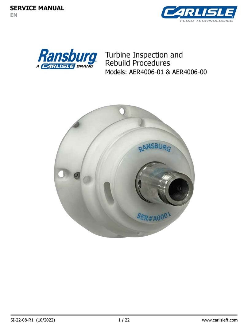
Carlisle Fluid Technologies Ransburg AER4006-01 User manual

Carlisle Fluid Technologies
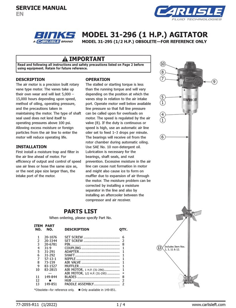
Carlisle Fluid Technologies BINKS 31-296 User manual

Carlisle Fluid Technologies
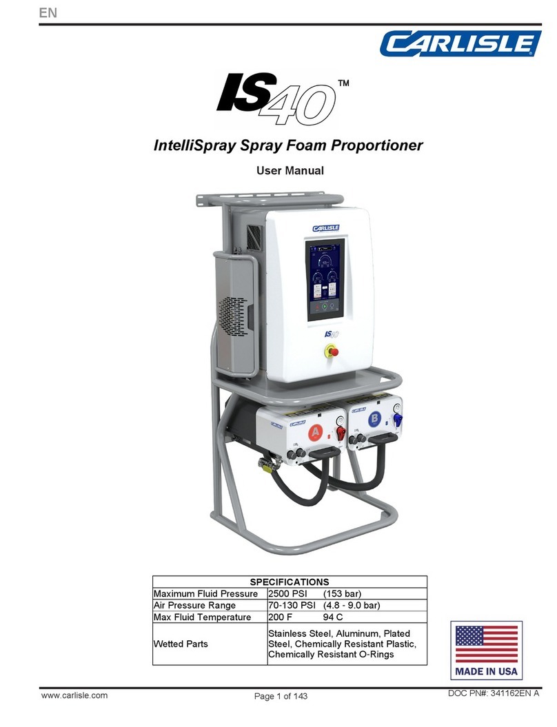
Carlisle Fluid Technologies IntelliSpray IS40 User manual

Carlisle Fluid Technologies
Carlisle Fluid Technologies Ransburg IntelliFlow RF2 User manual