NEUGART PLE User manual
PLE |PLQE | PLPE | PLHE |PLFE | PFHE
WPLE |WPLQE |WPLPE |WPLHE | WPLFE
PSBN |PSN |PLN |PSFN |PLFN
WPLN |WPSFN |WGN
NGV
DSS No. 100225283
DSS-Rev.
012
Date 12.07.2023
Operating Manual Gearbox
Economy gearboxes
Precision gearboxes
Application-specific gearboxes

2
Operating Manual Gearbox
Contents
Contents
1 General notes 4
1.1 Personnel qualification 4
1.2 Description of the gearbox 4
1.3 Intended use 5
1.4 Reasonably foreseeable misuse 5
1.5 Warnings 5
1.6 Contents and use of the operating manual 6
1.7 Further applicable documents 6
2 Description of the gearbox 7
2.1 Nameplate 7
2.1.1 Nameplate with data matrix code 7
2.1.2 Nameplate with serial number 8
2.2 Lubrication with low temperature lubricant 8
3 Storage and transport 9
3.1 Bearings 9
3.2 Transport 9
4 Mounting 10
4.1 Attaching the motor to the gearbox by means of a clamping system (motor attachment) 10
4.1.1 Attaching the motor 11
4.1.2 Attaching the motor shaft with a clamping system 12
4.1.3 Determining the radial run-out, axial run-out and coaxiality tolerance of the motor 13
4.2 Attaching the motor to the gearbox by means of the drive pinion (direct motor mounting) 14
4.3 Attaching the drive unit to the gearbox by means of the drive shaft
(free drive shaft)
15
4.4 Installing the gearbox in the application 17
4.4.1 Application side attachment to steel or aluminum 18
4.4.2 General tightening torques on the application side
Mounting bolts 19
4.4.3
Modified gearboxes: Strength class of the application-side mounting bolts and
use of washers
19
4.5 Radial and axial run-out of the gearbox shaft end 19
5 Commissioning and operation 21
5.1 Technical specifications 21
5.2 Initial operation (Commissioning) 21
5.2.1 Determining the lubricant service life 24
5.3 Operation 25
5.3.1 Remedying operational malfunctions 26
5.4 Inspection and maintenance 27
5.4.1 Inspection intervals and inspection measures 27
5.4.2 Maintenance operations 28
5.4.3 Safety data sheets 28
6 Disposal (instructions regarding hazardous substances, composition) 29
7 Service and manufacturer information 30
7.1 Service 30
7.1.1 Address and return shipments: 30
7.1.2 Locations in the USA and China 30
7.2 Manufacturer (company name and address) 30

3
Overview of revisions
Revision Chapter Reason for revision Revised by
Operating Manual Gearbox
Overview of revisions
4
1 General Information
1.1 Personnel qualification
In particular, mounting, commissioning, operation, maintenance and disposal of the
gearbox require qualified specialists who, due to their training, knowledge and ex-
perience in the field of mechanics and drive technology, are able to assess the work
assigned to them, recognize possible hazards, particularly misuse, and take suitable
preventive and protective measures.
1.2 Description of the gearbox
The gearbox has input and output shafts for the non-positive and positive mounting
of electric motors. By means of mechanical transmission elements, speeds and
torques are converted or transmitted by the drive and the output shaft in a form-fit,
material-fit or friction-locked manner. The drive and output shaft can accommodate
external loads.
The gearbox has a partially closed or closed housing.
The drive and the output shaft are usually freely accessible.
The geometric characteristics and performance data of the gearbox are described
in its technical specifications.
Operating Manual Gearbox
General notes
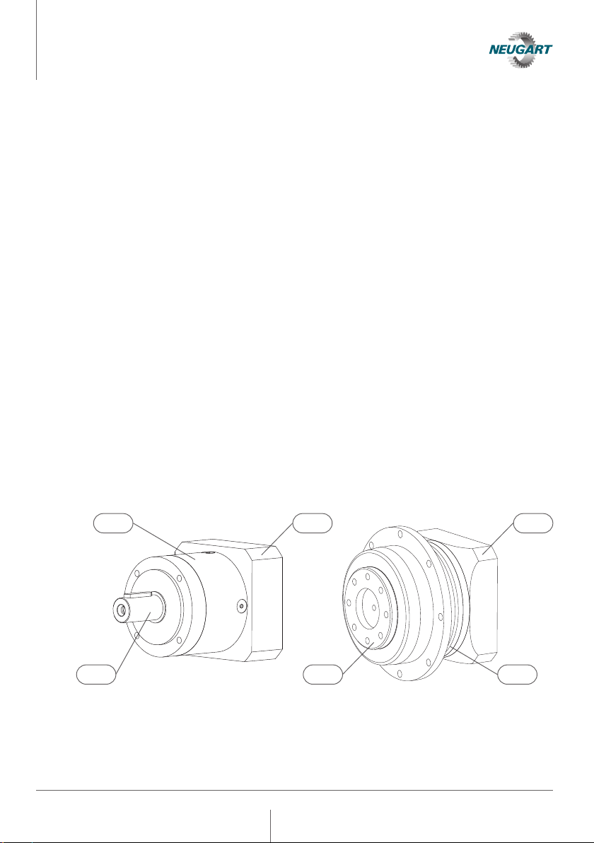
In the examples shown above, the following components of a planetary
gearbox are described:
1 Gearbox housing 3 Drive flange
2 Output shaft 4 Output shaft as flange output shaft
1
2
3 3
14
5
1.3 Designated use
The gearbox is intended exclusively for converting or transmitting torques, speeds
and for absorbing radial or axial loads in accordance with its technical specifications.
The gearbox may only be used for commercial and industrial reutilization.
1.4 Reasonably foreseeable misuse
Among other things, do not operate the gearbox in the following way:
• Without connecting element(s) on input or output shaft(s)
• Without monitoring and protective devices on the application side
• Outside the temperature range suitable for the lubricant
• Without consideration of the influence of the operating temperature on
the lubricant service life
• In potentially explosive atmospheres
• Outside the performance data provided in the technical specifications
Furthermore, interventions through technical modifications or conversions are not
permitted.
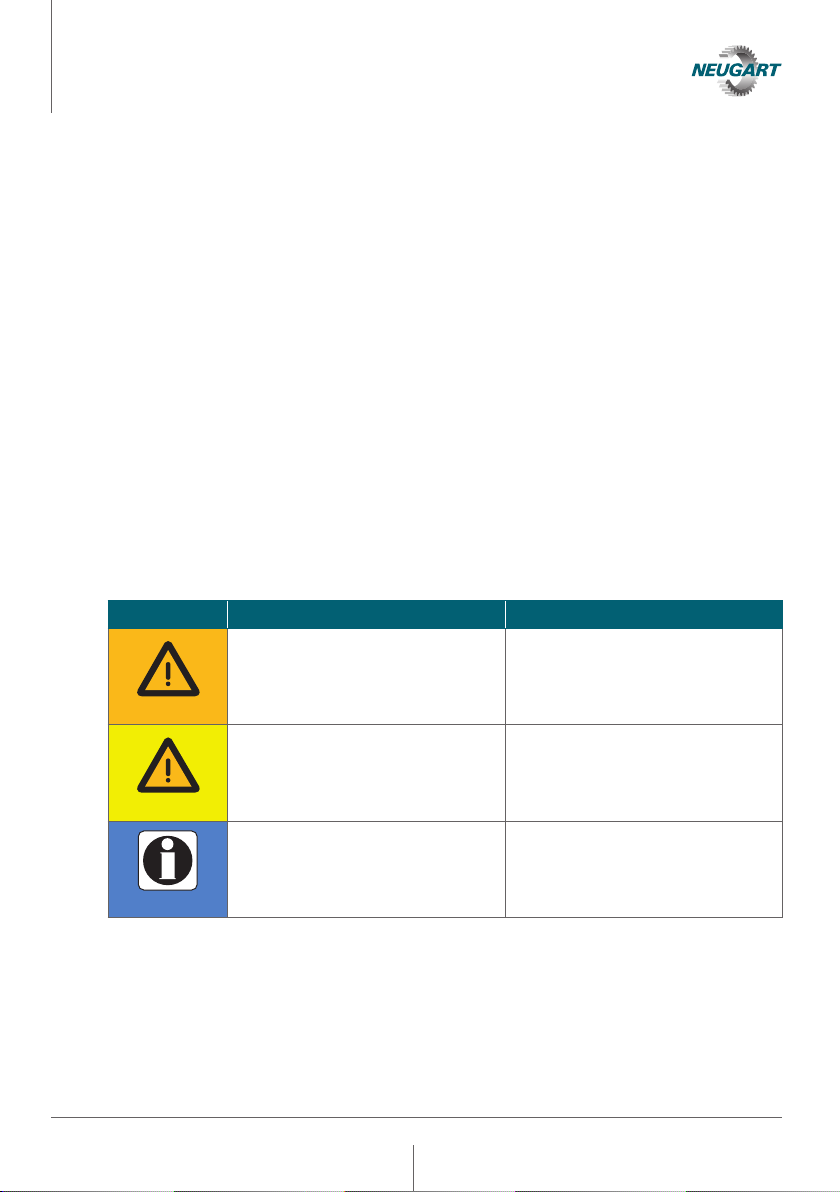
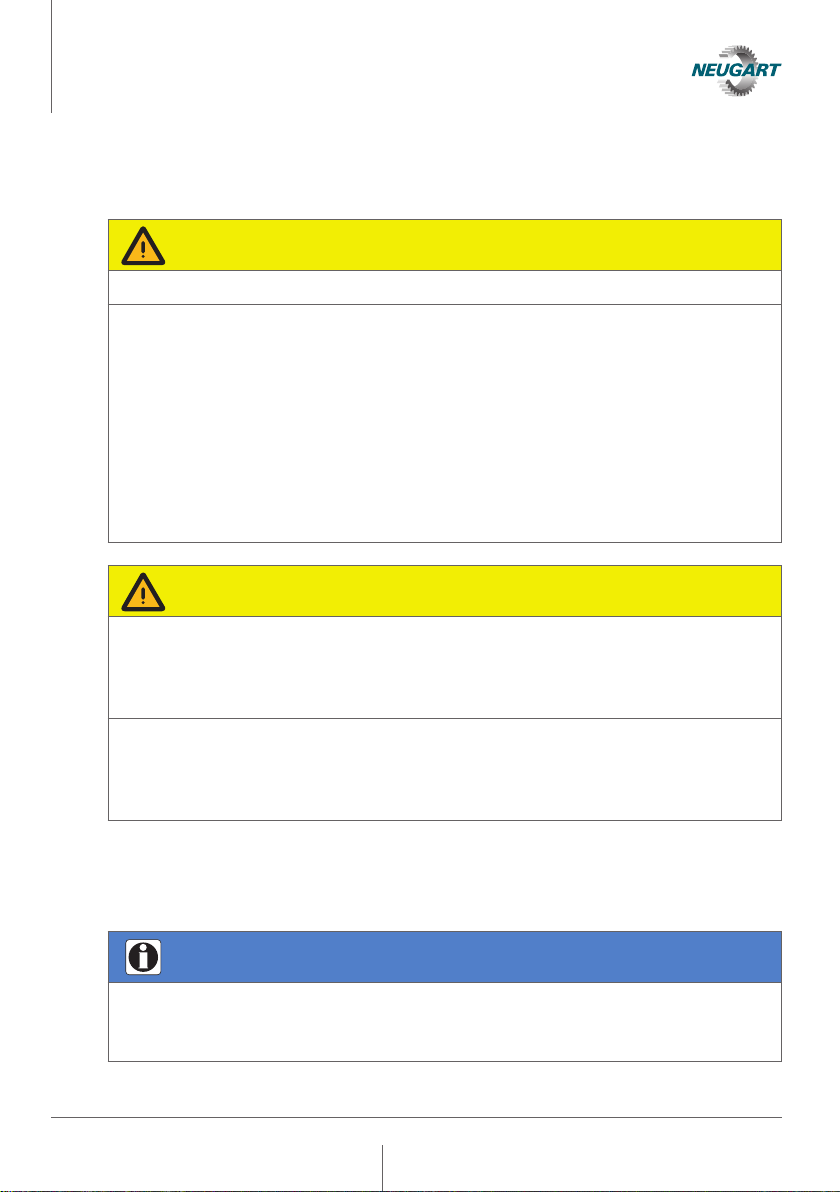
1.5 Warnings
Signal word
Explanation Consequences of non-compliance
Gefahr
Warning!
Possible imminent danger to life and
health
Serious injuries, including
death
Gefahr
Attention!
Possible imminent danger of property
or environmental damage
Damage to the drive system or its
environment
Information
Very important information: Simplifies
correct and safe installation and use of
the gearbox
Can lead to undesired developments
in the operating process
Operating Manual Gearbox
General notes

6
1.6 Content and use of the operating manual
This operating manual describes the conditions that must be met to ensure that the
gearbox can be started up properly without adversely affecting the safety and health
of persons. In addition, it contains specifications for all life phases of the gearbox.
The operating manual is only complete when with the further applicable documents.
If the operating manual refers to further applicable documents, these must be
observed.
The gearboxes described in this operating manual are based on a risk assessment
conducted in accordance with DIN EN ISO 12100: 2011-3.
1.7 Further applicable documents
• Technical specification (dimension spec sheet)
• Mounting instructions for the motor when mounted according to 4.1 as well as 4.2
Operating Manual Gearbox
General notes
7
Operating Manual Gearbox
Description of the gearbox
2 Description of the gearbox
2.1 Nameplate
The nameplate is affixed to the drive flange or the gearbox housing. For clear identi-
fication of the gearbox, the nameplate must also be legible at all times once installed
in a machine or system. There are two different versions of the nameplate, which are
explained in the following chapters 2.1.1 and 2.1.2.
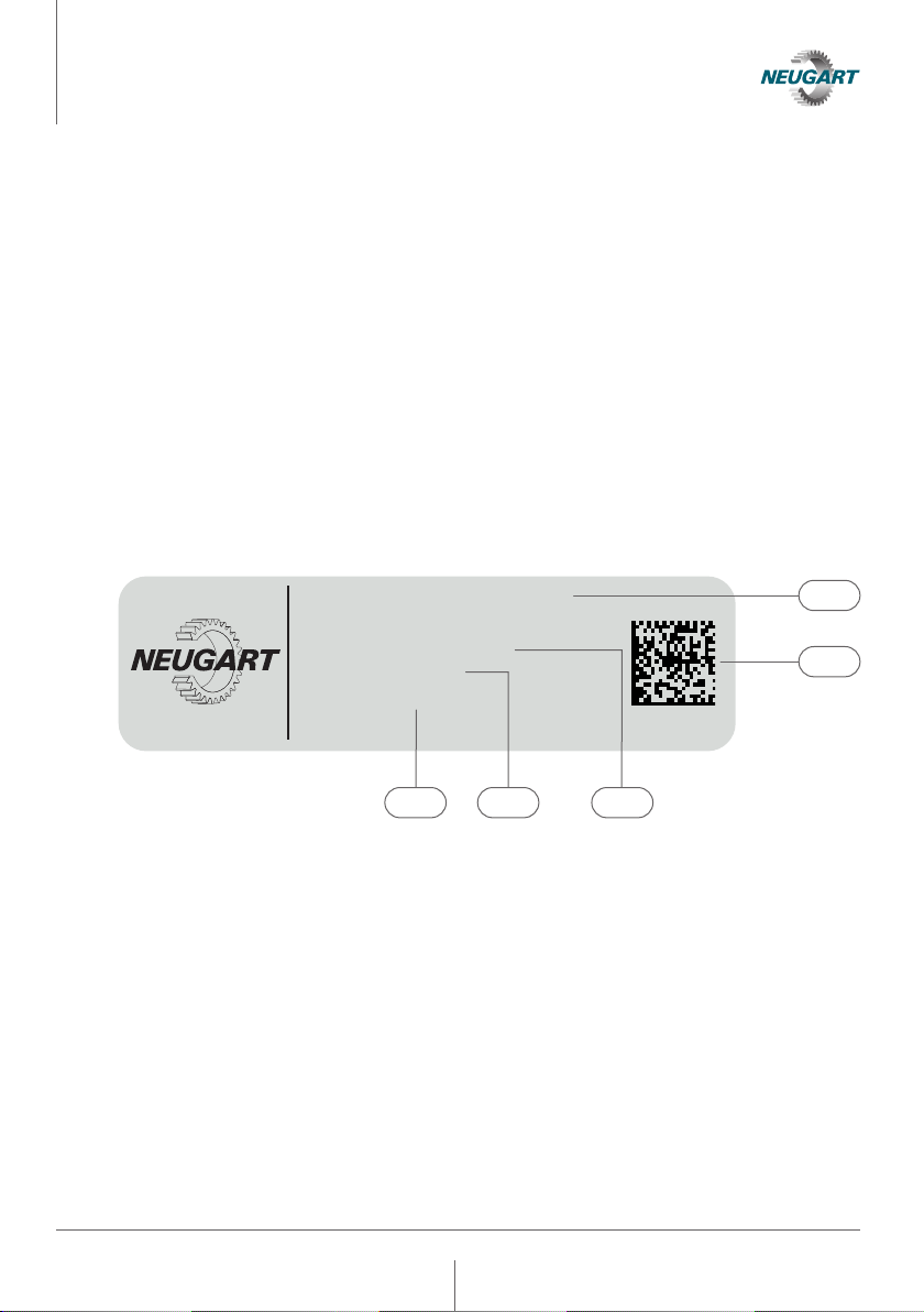
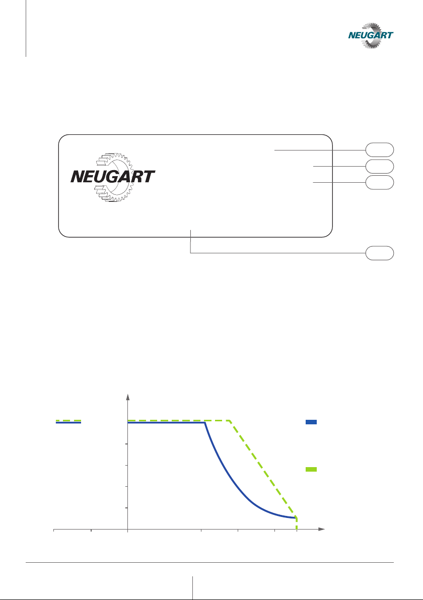
2.1.1 Nameplate with data matrix code
The following figure shows, by way of example. the nameplate of a PLE series
planetary gearbox with a data matrix code. The data matrix code links to the Online
Service, where more detailed product information can be accessed.
1 Product code (2 lines)
2 Data matrix code
3 Serial number
4 Article number
5 Production date: Calendar week / year
Made in Germany
PLE080-004-SSSA3AE-E19
/40/80/100/B5/M6
SN: MZRKPMCVRNB
AN: 100253786
DOP: 34/2022
5 4 3
2
1
8
Operating Manual Gearbox
Description of the gearbox
2.1.2 Nameplate with serial number
The following figure shows, by way of example, the nameplate of a planetary gearbox
from the PSN series with serial number:
1 Article number
2 Serial number
3 Product code (2 lines)
4 Production date: Month / year
2.2 Lubrication with low-temperature lubricant
Please note that the use of a low-temperature lubricant leads to different
performance data. For further details, please refer to the following diagram.
Art−No. 123456789
F−No. 2170569−1 − 002
PSN090-005-SFSA3AD-Z14
/30/80/100/B5/M6
Made in Germany 06/2016 www.neugart.com
4
2
3
1
Tmin -20 0 20 40 60 80 Tmax °C
80% T2N
60% T2N
40% T2N
20% T2N
Nm
100% T2N
PLE, PLQE, PLPE,
PLHE, PLFE, PFHE,
WPLE, WPLQE, WPLPE,
WPLHE, WPLFE, NGV
PSBN, PSN, PLN,
PSFN, PLFN,
WPLN, WPSFN, WGN

9
3 Storage and transport
3.1 Storage
Gefahr
Caution!
Improper storage can damage the gearbox. This can lead to premature aging of the
lubricant and sealing elements, which can greatly reduce or shorten their service
life or sealing effect.
• Choose a dry storage location to avoid corrosion.
• The long-term storage temperature must be kept between 0 C and +40 C because
of the lubricant's storage life and the possibility of lubricant or seal aging.
• Direct sunlight or UV radiation accelerates the aging process of the seals and
results in premature wear.
• To ensure lubricant serviceability, the storage period must not exceed 1 year.
3.2 Transport
Gefahr
Caution!
When lifting and moving the gearbox, there is a risk of it falling if it is not properly
secured. When the gearbox is being moved, there is a pinch point hazard between
the gearbox and other application components.
• Keep the gearbox weight and gearbox dimensions listed in its technical specifica-
tions in mind.
• The gearbox must be lifted by means of suitable lifting aids which wrap directly
around the gearbox housing.
Operating Manual Gearbox
Storage and transport
10
Operating Manual Gearbox
Mounting
4 Mounting
Gefahr
Caution!
A damaged gearbox may no longer meet its technical specifications.
• The gearbox must not show any mechanical damage, corrosion, or lubricant
leakage.
• The sealing elements must be protected from compressed air and aggressive
cleaning agents. For cleaning, use cold cleaning agents based on a gasoline
hydrocarbon.
• The mounting or removal of output elements or motors by means of striking,
pressing or the like must be avoided in order to protect the bearings. Use pullers
or heat connecting elements to be attached.
• Do not install a damaged gearbox in the application.
• Do not operate a damaged gearbox.
Gefahr
Caution!
The gearbox may no longer fully meet the warranted performance characteristics
or the maximum permissible operating temperature may be exceeded if the mate-
rials used are not sufficiently thermally conductive or if the heat storage capacity is
insufficient due to undersizing or the ventilation is inadequate.
• The application-side materials and sizing for connection geometries must be
specified for sufficient heat flow and heat capacity (e.g. aluminum or steel and
plate size equal to twice flange size).
• Ventilation must be ensured by convection or forced-air ventilation.
4.1 Attaching the motor to the gearbox by means of a clamping system
(motor attachment)
Information
If the gearbox is prepared for mounting a motor by means of a clamping system,
please refer to the mounting instructions supplied with the gearbox for detailed
information on mounting the motor to the gearbox.
11
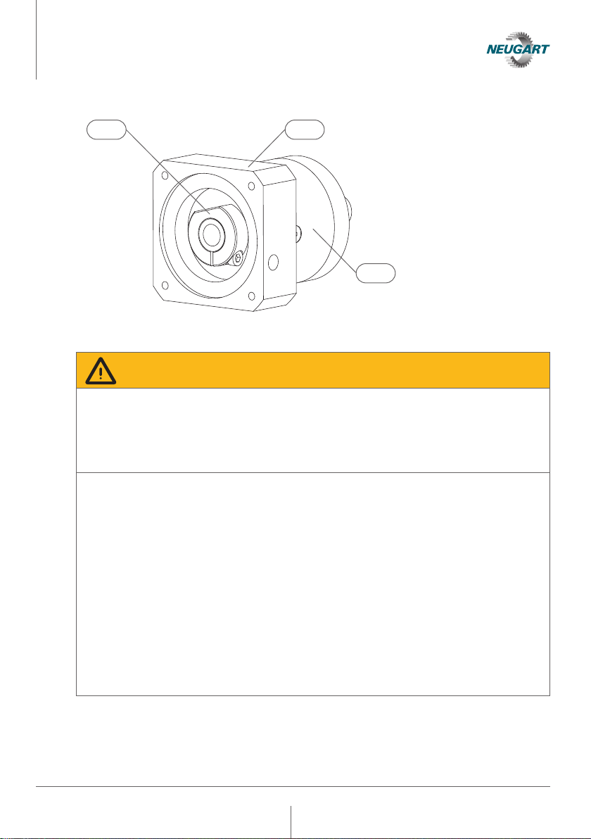
Operating Manual Gearbox
Mounting
1 Clamping System
2 Drive flange
3 Gearbox housing
4.1.1 Attaching the motor
Gefahr
Warning!
Due to its weight, incorrect mounting or in the event of unacceptable deviation from
radial run-out and axial run-out tolerances., the motor can cause a gear compo-
nent or a connecting element to break. Among other things, this can result in a
loss of position in the power train, uncontrolled rotation or a blocking of the output
shaft.
• The permissible motor weight or bending moment given in the technical specifi-
cation must be observed.
• The mounting instructions for motor mounting must be observed.
• Carefully clean the component surfaces to be used for non-positive connection
and remove all residues.
• Radial run-out and axial run-out tolerances must be ensured when mounting
a motor based on the values of the technical specification and the measuring
method described in 4.1.3.1 to 4.1.3.5.
• Observe the bolt tightening torques of the motor manufacturer when fastening
the motor.
• Select a suitable torque tool with a minimum accuracy to DIN EN ISO 6789-1
Type II A to ensure the required tightening torque.
• The bolts must be secured against self-loosening through use of a threadlocker
(e.g. Loctite 245).
21
3
12
4.1.2 Attaching the motor shaft with a clamping system
Gefahr
Warning!
Insufficient cleaning of the friction-locked components or insufficient tightening
torque (TAK) of the clamping screw can lead to slippage in the clamping system
and to its failure. Excessive tightening torque of the clamping screw can lead to its
breakage and thus to failure of the clamping system. This can result in uncontrolled
rotation of the output shaft, among other things.
• The mounting instructions for motor mounting must be observed.
• To protect against plastic deformation, the clamping system must not be pre-
loaded without the shaft installed.
• Carefully clean the component surfaces to be used for non-positive connection
and remove all residues.
• Observe the specified tightening torque (TAK) in the mounting instructions to
avoid slippage in the clamping system or breaking the clamping screw.
• Select a suitable torque tool with a minimum accuracy to
DIN EN ISO 6789-1 Type II A to ensure the required tightening torque.
Gefahr
Warning!
A motor shaft diameter not matched to the clamping system can lead to slippage in
the clamping connection and to its failure. This can result in uncontrolled rotation
of the output shaft, among other things.
• Make sure that the tolerance of the motor shaft is matched to the gearbox.
• The tolerance for the motor shaft diameter can be found in the technical specifi-
cations.
Gefahr
Warning!
The clamping screw has specific characteristics. The use of a clamping screw other
than the original screw can lead to failure of the clamping connection.
• Use only the original screw.
• Use only a replacement part provided by Neugart.
Operating Manual Gearbox
Mounting
13
4.1.3 Determining the radial run-out, axial run-out and coaxiality tolerance of the motor
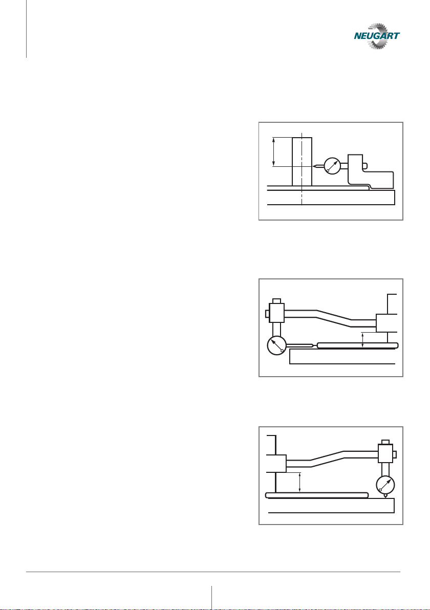
4.1.3.1 Radial run-out of the motor shaft end
The measuring probe is placed at the center
of the shaft end. The maximum and minimum
values are read on the measuring instrument
by slowly rotating the shaft. The measurement
may be performed with the motor in a hori-
zontal or vertical position, with the measuring
instrument mounted directly on the motor or
on a common base plate for the motor and
measuring instrument. The difference between
these readings must not exceed the values
given in the technical specifications of the
gearbox.
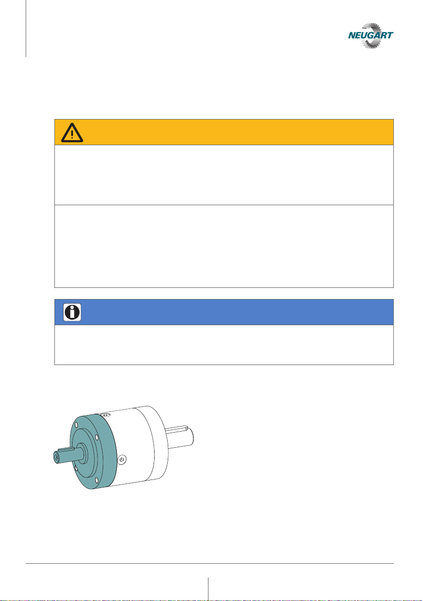
4.1.3.2 Coaxiality of flange centering with respect to the motor shaft
Using a fixture similar to the one shown in the
picture,the measuring instrument is mounted
on the shaft end at a distance of about 10 mm
from the mounting surface of the flange. The
maximum and minimum values are read on
the measuring instrument by slowly rotating
the shaft. It is recommended that the shaft
be oriented vertically when performing this
measurement. The difference between these
readings must not exceed the values given in
the technical specifications of the gearbox.
4.1.3.3 Axial run-out of the mounting surface of the flange with respect to the motor shaft
Using a fixture similar to the one shown in the
picture,the measuring instrument is mounted
on the shaft end at a distance of about 10 mm
from the mounting surface of the flange. The
maximum and minimum values are read on
the measuring instrument by slowly rotating
the shaft. It is recommended that the shaft
be oriented vertically when performing this
measurement. The difference between these
readings must not exceed the values given in
the technical specifications of the gearbox.
Operating Manual Gearbox
Mounting
E/2
10
10

14
Operating Manual Gearbox
Mounting
4.1.3.4 Radial run-out tolerance of the motor shaft
Nominal
motor shaft
diameter
[mm]
Radial run-out tolerance [mm]
PLE, PLQE, PLPE, PLHE, PLFE, PFHE,
WPLE, WPLQE, WPLPE, WPLFE,
WPLHE, NGV
PSBN, PSN, PLN, PSFN, PLFN,
WPLN, WPSFN, WGN
0 — ≤10
0.03
0.015
>10 — ≤30
0.04
0.020
>30 — ≤50
0.05
0.025
>50 — ≤80
0.06
0.030
4.1.3.5 Axial run-out and coaxiality tolerance of the motor flange
Flange size/
Square
measure
[mm]
Axial runout and coaxiality tolerance [mm]
PLE, PLQE, PLPE, PLHE, PLFE, PFHE,
WPLE, WPLQE, WPLPE, WPLFE,
WPLHE, NGV
PSBN, PSN, PLN, PSFN, PLFN,
WPLN, WPSFN, WGN
0 — ≤40
0.06
0.03
>40 — ≤100
0.08
0.04
>100 — ≤230
0.10
0.05
>230 — ≤450
0.13
0.06
4.2 Attaching the motor to the gearbox by means of the drive pinion
(direct motor mounting)
Information
If the gearbox is prepared for mounting a motor by means of a drive pinion directly
connected to the motor shaft, please refer to the mounting instructions supplied
with the gearbox for detailed information on mounting the motor to the gearbox or
connecting the drive pinion to the motor shaft.
15
4.3 Attaching the drive unit to the gearbox by means of the drive shaft
(free drive shaft)
Gefahr
Warning!
Due to its weight, faulty mounting, a technically faulty connection between the
motor shaft and drive pinion or in the event of impermissible deviation from the
radial and axial run-out tolerances, the motor can cause breakage of torque-
transmitting gearbox components or slip in the connection. This can result in un-
controlled rotation or blocking of the output shaft, among other things.
• The permissible motor weight or bending moment given in the technical specifi-
cations must be observed.
• The instructions for motor and drive pinion mounting must be followed.
• The radial and axial run-out tolerances required in the motor and drive pinion
mounting instructions must be satisfied with the drive pinion attached.
• The design of the connection between the motor shaft and the drive pinion
must ensure the performance data of the technical specifications.
Information
If the gearbox is prepared for attachment of a drive unit by means of a drive shaft
mounted on the gearbox, the same mounting specifications listed in 4.4 apply to the
application connection on the input and output sides.
Operating Manual Gearbox
Mounting

16
Gefahr
Warning!
Incorrect connection or pretensioning of the drive-side connecting element can
cause breakage or slippage in the connection between the drive shaft and con-
necting element. This can result in breakage of a gear component or connecting
element, loss of position in the power train, or premature bearing failure. This can
result in uncontrolled rotation or blocking of the output shaft, among other things.
• If so indicated in the specifications, the gearbox must be connected to the appli-
cation with the flange geometry shown on the input and output sides.
• The permissible external loads listed in the technical specifications must be
observed.
• An uncontrolled introduction of external forces due to "overspecified" operating
conditions (e.g. additional application-side bearings for the drive shaft, excessive
belt tension when using a belt pulley) can lead to breakage of the drive shaft or
failure of the gearbox bearings. Suitable connecting elements must be used and
positional deviations must be avoided.
Operating Manual Gearbox
Mounting

17
4.4 Installing the gearbox in the application
Gefahr
Warning!
Incorrect attachment to the application can lead to misalignment or slippage in the
connection between the gearbox and application or gearbox shafts and connecting
elements. This can lead to breakage of a gear component, a connecting element
or loss of position in the power train, which can result in uncontrolled rotation or
blocking of the output shaft, among other things.
• Observe the strength class of the application-side mounting bolts and possible
use of washers according to 4.4.1
• Observe the tightening torques for the application-side mounting bolts and the
requirements in 4.4.1 and 4.4.2
• Select a suitable torque tool with a minimum accuracy to DIN EN ISO 6789-1
Type II A to ensure the required tightening torque.
• The bolts must be secured against self-loosening through use of a threadlocker
(e.g. Loctite 245).
• Non-positive connections must be made with suitable clamping sets and the
appropriate fit according to the shaft fits given in the technical specifications in
order to avoid slippage.
• Carefully clean the component surfaces to be used for non-positive connection
and remove all residues.
• The application-side flange geometry must be free of damage and residues.
• Uncontrolled introduction of external forces due to "overspecified" operating
conditions can lead to shaft breakage or failure of the gearbox bearings. Overspe-
cified operating conditions can include positional deviations between the gearbox
and the application, jamming in the case of direct connection to translational ap-
plications e.g. rack and pinion, additional application-side bearings for the input
or output shaft or excessive pretensioning of belts. Suitable connecting elements
must be used and positional deviations must be avoided.
Operating Manual Gearbox
Mounting
18
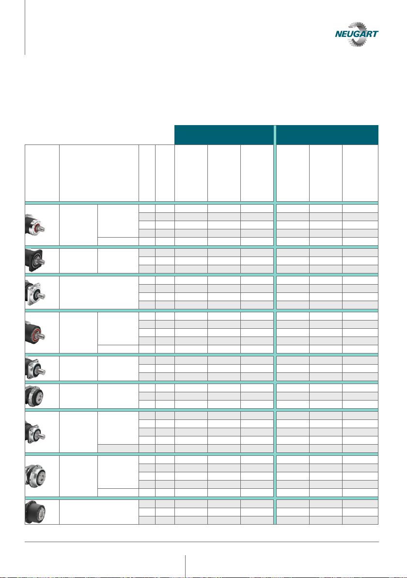
4.4.1 Application side attachment to steel or aluminum
Table 4.4.1 shows the strength class to be used and the tightening torque for the
application-side mounting bolts, as well as the use of washers for application-side
attachment to steel or aluminum.
Application-side
attachment to steel
Application-side
attachment to aluminum
Gearbox
(sample
image)
Series
Frame size
Bolt size
Mounting bolt
strength class
Washer required
Tightening-
torque
[Nm]
Mounting bolt
strength class
Washer required
Tightening-
torque
[Nm]
PLE WPLE
040 M4 10.9 no 3.8 10.9 yes 3.8
060 M5 10.9 no 7.5 10.9 yes 7.5
080 M6 10.9 no 12.9 10.9 yes 12.9
120 M10 10.9 no 61 10.9 yes 61
160 M12 12.9 no 123 12.9 yes 123
PLQE WPLQE
060 M5 12.9 yes 8.7 10.9 yes 7.5
080 M6 12.9 no 15.1 10.9 no 12.9
120 M8 12.9 yes 36 10.9 yes 31
PSBN
070 M5 12.9 yes 8.7 10.9 yes 7.5
090 M6 12.9 yes 15.1 10.9 yes 12.9
115 M8 12.9 yes 36 10.9 yes 31
142 M10 12.9 yes 72 10.9 yes 61
PLPE WPLPE
050 M4 12.9 no 4.4 12.9 yes 4.4
070 M5 12.9 no 8.7 12.9 yes 8.7
090 M6 12.9 no 15.1 12.9 yes 15.1
120 M8 12.9 no 36 12.9 yes 36
155 M10 12.9 no 72 12.9 yes 72
PLHE WPLHE
060 M5 12.9 yes 8.7 10.9 yes 7.5
080 M6 12.9 no 15.1 10.9 no 12.9
120 M8 12.9 no 36 10.9 no 31
PLFE
PFHE WPLFE
064 M4 12.9 no 4.4 10.9 no 3.8
090 M5 12.9 no 8.7 10.9 no 7.5
110 M5 12.9 no 8.7 10.9 no 7.5
PSN
PLN
WPLN
WGN
070 M5 12.9 yes 8.7 10.9 yes 7.5
090 M6 12.9 no 15.1 10.9 no 12.9
115 M8 12.9 no 36 10.9 no 31
142 M10 12.9 no 72 10.9 no 61
190 M12 12.9 no 123 10.9 no 105
PSFN
PLFN WPSFN
064 M4 12.9 no 4.4 10.9 no 3.8
090 M5 12.9 no 8.7 10.9 no 7.5
110 M5 12.9 no 8.7 10.9 no 7.5
140 M6 12.9 no 15.1 10.9 no 12.9
200 M8 12.9 no 36 10.9 no 31
NGV
064 M5 12.9 no 8.7 10.9 no 7.5
090 M6 12.9 no 15.1 10.9 no 12.9
110 M8 12.9 no 36 10.9 no 31
Operating Manual Gearbox
Mounting

19
4.4.2 General tightening torques on the application side
Tightening torques for the application-side mounting bolts [Nm]
Strength class
Mounting bolts M3 M4 M5 M6 M8 M10 M12 M16
10.9 1.6 3.8 7.5 12.9 31 61 105 257
12.9 1.9 4.4 8.7 15.1 36 72 123 300
General conditions for establishing the tightening torques
• Design of bolted connection in accordance with VDI 2230
• The total coefficient of friction for thread and head support is µ
total
=0.1
• Up to 90% of the bolt yield strength is used
• The max. permissible tightening torque minus the accuracy class of the
mounting tool (the accuracy class of the mounting tool must satisfy
DIN EN ISO 6789-1 Type II A at a minimum)
4.4.3 Modified gearboxes: Strength class of the application-side mounting bolts and use
of washers
Table 4.4.3 shows the strength class of the application-side mounting bolts to be
used for modified gearboxes, as well as the use of washers, for application-side
attachment on steel or aluminum. For painted gearboxes, we recommend the use of
washers to protect the paint layer.
Material
Gearbox side
Aluminum Aluminum Aluminum
Steel Steel Steel
Design
Gearbox side
Thread Holes Oblong
holes Thread Holes Oblong
holes
Application
side
of steel
Strength class
Mounting bolts 10.9 12.9 12.9 12.9 12.9 12.9
Washer
required no yes yes no no yes
Application
side
of aluminum
Strength class
Mounting bolts 10.9 10.9 10.9 12.9 10.9 10.9
Washer
required yes yes yes yes no yes
Operating Manual Gearbox
Mounting
20
Operating Manual Gearbox
Commissioning and operation
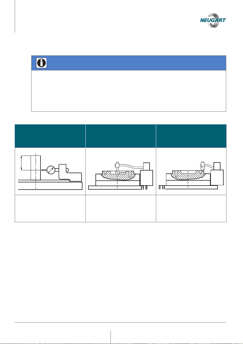
4.5 Radial and axial run-out of the gearbox shaft end
Information
If the technical specifications include data on the radial and axial run-out of the
output shaft, the measuring methods described below must be used. The measure-
ment may be performed with the gearbox in the horizontal or vertical position, with
the measuring instrument mounted directly on the gearbox or on a common base
plate for the gearbox and measuring instrument. The maximum and minimum
values are read on the measuring instrument by slowly rotating the shaft.
Radial run-out
of the gearbox shaft end
for stem shafts
Radial run-out
of the gearbox shaft end
for flanged shafts
Axial run-out
of the gearbox shaft end
for flanged shafts
E/2
The measuring probe is
placed at the center of the
shaft end.
The measuring probe is
placed at the center of the
inner centering diameter of
the flanged shaft.
The measuring probe is
placed at the outer edge of
the screw-on surface of
the flanged shaft.
This manual suits for next models
19
Table of contents
Other NEUGART Industrial Equipment manuals

Popular Industrial Equipment manuals by other brands


Linn-High-Therm
Linn-High-Therm HT-1500-GT-VAC Special GRAPHITE operating instructions

Spirotech
Spirotech SpiroVent Superior S6 Series user manual

ABB
ABB AFS670 Safety instructions

Hydrotech
Hydrotech HSF2200 Series Operation & maintenance manual

Siemens
Siemens 3WN6 operating instructions

National Instruments
National Instruments VXIpc 770 Series user manual


