CARLO GAVAZZI PQT-90 User manual

OUR PRODUCTION SITES
Carlo Gavazzi Industri A/S
Hadsten - DENMARK
Inductive and Capacitive
Proximity
Sensors in full metal and
plastic
housings. Photoelectric
Sensors.
Level Sensors: Optical,
Conductive
and Capacitive.
Ultrasonic Sensors and
Magnetic
Switches. Limit Switches.
Dupline Field and Installation
Bus.
Building Automation Systems.
Carlo Gavazzi Ltd
Zejtun - MALTA
Solid States Relays.
Versions for PCB and panel
mounting.
AC Semiconductor Motor
Controllers
Soft starters.
Industrial and PCB Relays.
Carlo Gavazzi Controls SpA
Belluno - ITALY
Energy Management.
Timers and Monitoring
Relays.
Digital Panel Meters and
Temperature Controllers.
SAIET Elettronica SpA
Castel Maggiore (BO) - ITALY
Safety and Magnetic
Switches,
Safety Modules.
Mat Systems, Light Curtains,
Electrical Transient,
Protections.
Measuring Systems and
Encoders.
Software for PQT90 data download and configuration
CARLO GAVAZZI
Automation Components
OUR SALES NETWORK
Carlo Gavazzi GmbH
Wien - AUSTRIA
Carlo Gavazzi NV/SA
Vilvoorde - BELGIUM
Carlo Gavazzi Inc.
Mississauga, ON - CANADA
Montreal, PQ - CANADA
Carlo Gavazzi Handel A/S
Hadsten - DENMARK
Carlo Gavazzi OY AB
Helsinki - FINLAND
Carlo Gavazzi Sarl
Roissy - FRANCE
Carlo Gavazzi GmbH
Weiterstadt - GERMANY
Carlo Gavazzi UK Ltd
Aldershot - GREAT BRITAIN
Carlo Gavazzi SpA
Lainate (MI) - ITALY
Carlo Gavazzi Automation Sdn Bhd
Petaling Jaya, Selangor - MALAYSIA
Carlo Gavazzi BV
Beverwijk - NETHERLANDS
Carlo Gavazzi AS
Porsgrunn - NORWAY
Carlo Gavazzi Lda
Lisboa - PORTUGAL
Carlo Gavazzi SA
Leioa (Bizkaia) - SPAIN
Carlo Gavazzi AB
Karlstad - SWEDEN
Carlo Gavazzi AG
Steinhausen - SWITZERLAND
Carlo Gavazzi Inc.
Buffalo Grove IL - USA
Further information on www.carlogavazzi.com
CARLO GAVAZZI
Automation Components
PqtSoft Network-Remote
PQT-90
INSTRUCTION MANUAL

PQT-90: Modular network power
quality transducer
Harmonic analysis; Energy meters;
Plug and play module system;
SMS reception and transmission.
These are only a few among the
functions of PQT-90. What’s more,
Carlo Gavazzi means ISO9001 cer-
tification, a working experience of
many decades and a world-wide
organization. All this because we
want our customers to have the
top products and the top service.
Welcome in the Carlo Gavazzi world
and compliments for your smart
choice. Visit our Website and eval-
uate our wide range of products:
www.carlogavazzi.com/ac
T
H
A
N
K
Y
O
U
F
O
R
C
H
O
O
S
I
N
G
C
A
R
L
O
G
A
V
A
Z
Z
I
CARLO GAVAZZI
Automation Components
SMS
messages

Index
4
3
2Warnings
PQTSoft Remote
SETUP . . . . . . . . . . . . . . . . . . . . . . . . . . . . . . . . . . . . .05
■PQTSoft Remote Setup . . . . . . . . . . . . . . . . . . . .05
■PQTSoft Remote Uninstall . . . . . . . . . . . . . . . . . . .05
■PQTSoft Remote in brief . . . . . . . . . . . . . . . . . . . .06
CONFIGURATION . . . . . . . . . . . . . . . . . . . . . . . . . . . . .08
■Main menu . . . . . . . . . . . . . . . . . . . . . . . . . . . . . .08
❑
Configuration archive and remote PQT programming
. . .08
❑Instrument composition... . . . . . . . . . . . . . . . .09
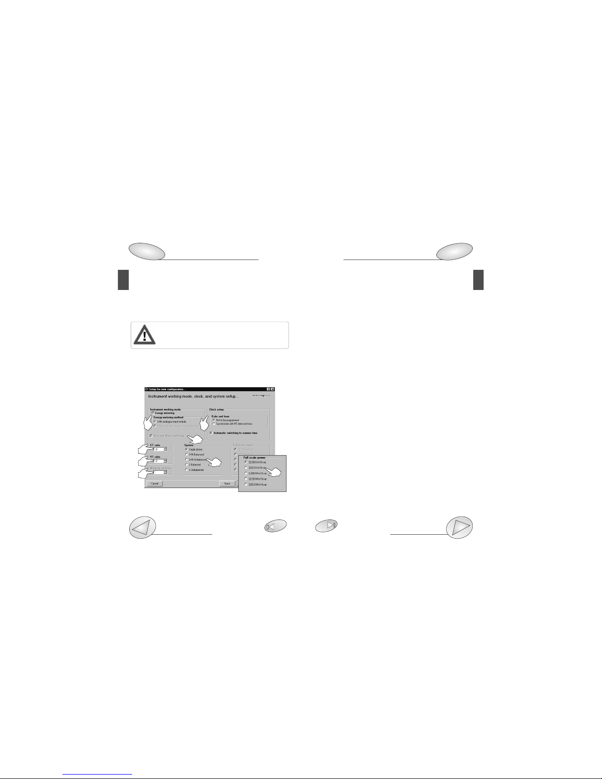
❑Instrument working mode, clock and system setup .10
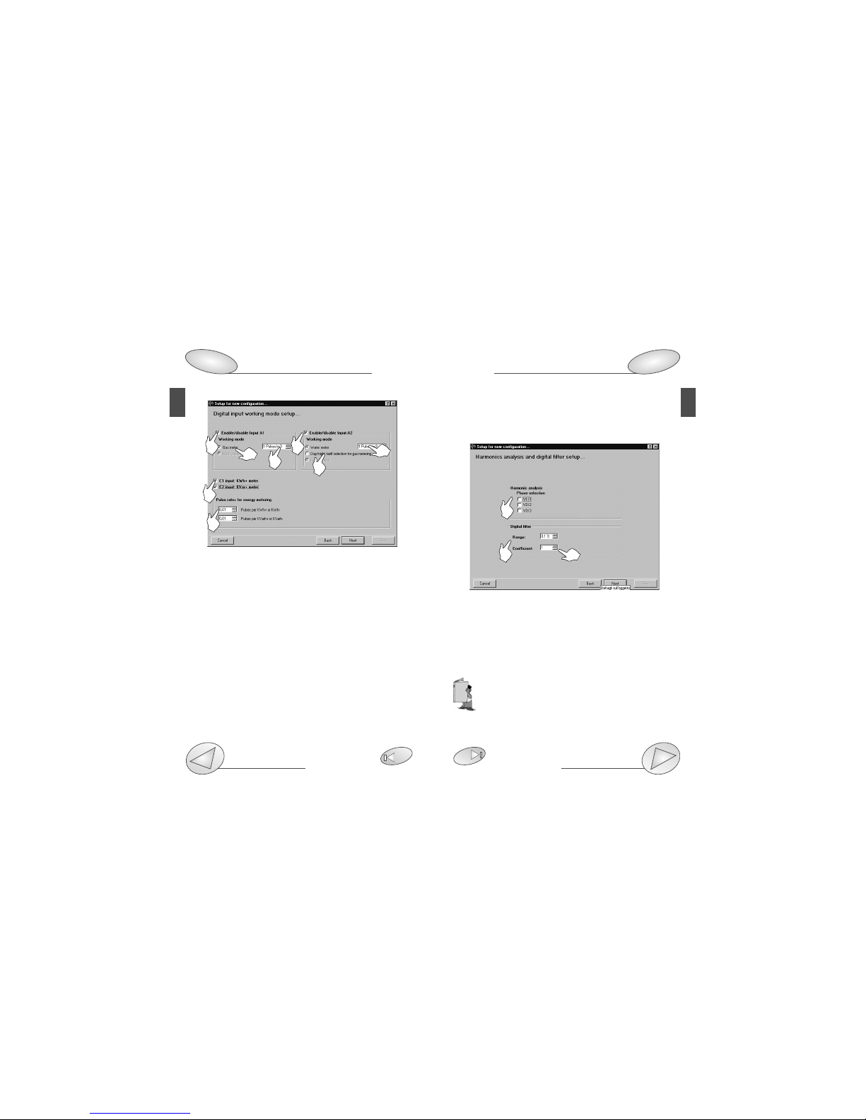
❑Digital input working mode setup . . . . . . . . . .12
❑Harmonics analysis and digital filter setup . . .13
❑Setup of min-max values logging + rel. variables . .15
❑Logging variables selection + dmd power calculation . .16
❑Tariffs and installed power setup . . . . . . . . . .18
❑Dual-tariff setup . . . . . . . . . . . . . . . . . . . . . . .19
❑Multi-tariff setup . . . . . . . . . . . . . . . . . . . . . . .21
❑Multi-tariff setup with digital inputs . . . . . . . . .23
❑Digital output setup . . . . . . . . . . . . . . . . . . . .24
❑Digital output alarm setup . . . . . . . . . . . . . . .26
❑Analogue output alarm setup . . . . . . . . . . . . .27
❑Set SMS messages and phone numbers . . . . . . .30
TRANSMISSION OF THE CONFIGURATION . . . . . . . .32
■Transmit the configuration . . . . . . . . . . . . . . . . . .32
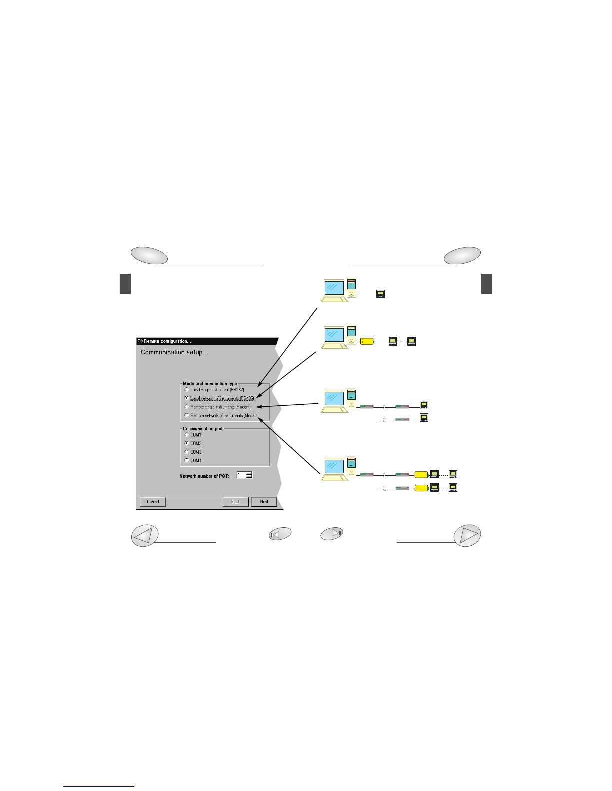
❑Communication setup . . . . . . . . . . . . . . . . . .33
❑Phone numbers and dialling properties . . . . .34
❑
Network address and warning messages
. . . . . .35
■Reading of instantaneous variables . . . . . . . . . . . . . .35
LAST FUNCTIONS . . . . . . . . . . . . . . . . . . . . . . . . . . . .36
■Reset of partial and total meters. . . . . . . . . . . . . .36
■Automatic modem configuration. . . . . . . . . . . . . .36
■Selection of connections and setting of dialling properties 37
❑Dialling properties. . . . . . . . . . . . . . . . . . . . . .38
PQTSoft Remote and Network, PQT-90 modular
quality network transducer,Instruction manual:
FW rev. 01 CARLO GAVAZZI Controls SpA
We suggest you to keep the orginal packing in case
it is necessary to return the instrument to our
Technical Service Department. In order to achieve
the best results with your instrument, we recommen
you to read this instruction manual carefully. When opening
the packing, verify that the product is not damaged and that
the following material is included: 1 PQT-90, 1 CD-ROM with
the programming software, 1 instruction manual (one RS232
serial connection cable). PQT-90 must be equipped with all the
modules necessary for its correct use. Before using the instru-
ment, follow the instructions on page 40.
MEANING OF THE SYMBOLS USED IN THIS MANUAL
See correlated subject on page ...
Chapter starts on page...
Chapter ends on page...
Particularly important subject or information
More details are given on the current subject
99
99

Setup 5
PQTSoft Remote
4Index
3
PQT-90
INSTALLATION . . . . . . . . . . . . . . . . . . . . . . . . . . . . . . .40
■Overall dimensions, DIN-rail mounting . . . . . . . . . . . . .41
■Position of slots and relevant modules . . . . . . . . .42
■Connection of optional modules . . . . . . . . . . . . . .45
■Electrical diagrams . . . . . . . . . . . . . . . . . . . . . . . .49
Useful info . . . . . . . . . . . . . . . . . . . . . . . . . . . . . . . . . .53
■Data logging operating principle and duration . . .53
■Appl. bar: meaning of the icons . . . . . . . . . . . . . .56
■How to use SMS messages . . . . . . . . . . . . . . . . .56
TECHNICAL FEATURES . . . . . . . . . . . . . . . . . . . . . . . .59
PQTSoft Network
PRELIMINARIES . . . . . . . . . . . . . . . . . . . . . . . . . . . . . .68
■Installing PQTSoft Network . . . . . . . . . . . . . . . . .68
■The software in brief . . . . . . . . . . . . . . . . . . . . . . .69
CONFIGURATION . . . . . . . . . . . . . . . . . . . . . . . . . . . . .72
■Main menu . . . . . . . . . . . . . . . . . . . . . . . . . . . . . .72
■ Configuration of automatic data download . . . . . .73
❑Setting of communication parameters . . . . . .73
❑Selection of phone numbers and diall. prop. .74
❑Folder selection for data files, counter . . . . . . .
file and event file . . . . . . . . . . . . . . . . . . . . . .75
❑If “Local network of instruments” was selected . .76
❑Setting expiry date for automatic data download . . .76
■ Configuration of data manual download . . . . . . . .78
❑Communication setup . . . . . . . . . . . . . . . . . .78
❑Selection of phone numbers and setting of . . .
dialling properties . . . . . . . . . . . . . . . . . . . . .79
❑Define file name for downloaded data . . . . . .80
❑Selection of “Local network instrument” . . . . .81
■ Reading of instantaneous variables . . . . . . . . . . .82
LAST FUNCTIONS . . . . . . . . . . . . . . . . . . . . . . . . . . . . . . . . . . . . .84
■ Configuration of analogue modem and GSM . . . .84
■ Contact management . . . . . . . . . . . . . . . . . . . . . .85
■PQT-90 data conversion in excel format . . . . . . . .88
Main menu
78
■PQTSof Remote setup
When the CD-ROM is
inserted, the setup pro-
gramme is automatically
executed (the CD-ROM
drive is to be enabled) and
the box on the left is dis-
played.
If the setup will not run,
click on the right key of
the mouse and select the
“explore CD-ROM” com-
mand: then, double click
the icon
to manually execute the application.
Afterwards, choose the operating system and the desired
language from the drop-down menu (see picture above).
Press “Install” to carry on with the installation following the
“instructions” given in the following dialog boxes. Save all
current jobs and close all open applications before
installing PQTSoft Remote.
■“PQTSoft Remote” Uninstall
Select “Uninstall PQTsoft Remote” to start the guided unin-
stallation of PQTSoft.

PQTSoft Remote Setup
Communication setup 33
7
PQTSoft Remote
6Setup
5
■PQTSoft Remote in brief
PQTSoft Remote has been conceived to program PQT-90
by means of a data transmission from the PC to the instru-
ment via RS232 or RS485 serial interface. The choice
between one interface or the other is therefore very impor-
tant for the correct operation of the instrument as shown
by the following figure:
Local single PQT connected to
the PC by RS232 serial port
Maximum 255 PQT’s in an RS485 local network connected
to the PC by RS232 thanks to the RS485-RS232 SIU-PC
converter.
Maximum 100 remote single PQT’s connected to the PC by
means of a telephone network thanks to an analogue/GSM
modem.
Maximum 25000 PQT’s in max 100 remote RS485 networks
connected to the PC by means of a telephone network and
RS485-RS232 SIU-PC.
RS232
RS485RS485
SIU-PC
RS232
... MAX255
RS232 RS232
MODEM MODEM
Telephone network
... MAX100
RS232 RS232
Telephone network RS485
MODEM MODEM SIU-PC
... MAX100
... MAX255
... MAX255

PQTSoft Remote Configuration
Available modules
29 42
9
■Main menu
1- Drop-down menu of the functions
2- Programming of PQT-90 and programming start-up
3- Reading of instantaneous variables (page 35)
4- Reset of all the water and gas energy meters (page 36)
5- Automatic configuration of analogue modem (page 36)
6- Automatic configuration of GSM modem (page 36)
7- Contact management (page 37)
8- Programme status.
■Configuration of PQT-90
❑Configurations archive and remote PQT programming
PQTSoft Remote
8Configuration
1345
2
2
1
3
PQTSoft Remote manages a configuration archive that may be
selected at any time. At first, when the software has just been
installed, this file is empty. [1] Click on new configuration to start
the programming procedure of PQT90. [2] It allows to load from
PQT-90 the pre-existing programming and to modify it, if
required. [3] Close the window without modifications.
❑Instrument composition...
[1] Enter the name required for the new configuration of PQT-90.
[2] Select the supplied modules installed in the instrument in
the various slots. For the module AR1041 only, if it is present,
also the operating mode is to be indicated as follows:
“AR1041 module (slave)”: PQT-90 is enabled to the data-
download only on request of the user;
“AR1041 module with analogue or GSM (Master+Slave)”
modem: PQT-90 is enabled to the data download on request
and to the independent transmission of SMS in case of
alarm activation;
“AR1041 module with GSM modem for SMS (Master)”:
PQT-90 is enabled to transmit SMS messages and to send
8
67
2
1
3

or without analogue measuring inputs (AQ1018, AQ10109)
[2] Enables the gas and water metering.
[3] Selects the ratio of the current transformer. Example: if
the CT (current transformer) primary has a current of 300A
and the secondary a current of 5A, the CT ratio corresponds
to 60 (that results from: 300/5).
[4] Selects the value of the VT (voltage transformer) ratio.
Example: if the VT primary connected to the instrument is
20kV and the secondary is 100V, the VT ratio corresponds
to 200 (resulting from 20000/100).
[5] Selects the serial address of the instrument when the lat-
ter is part of a network of instruments.
[6] Selects the type of electrical system. If no measuring
inputs (AQ1018, AQ1019) have been selected on the previ-
ous page, the box “Full scale power” will appear: select the
most appropriate full scale.
[7] Selects the options for the clock of PQT-90. If the option
“Not to be programmed” is selected, the clock will not be
programmed; to program the hour, select the option
“Synchronize with PC date and hour”, the clock will be pro-
grammed with the date and hour present in the system of
the PC. To make the instrument automatically switch to the
summer time and viceversa, select the option “Automatic
switching to summer time”.
PQTSoft Remote
29
11
SMS messages when an alarm occurs. To carry out the data
download, in this case, it is necessary to use the RS485
serial module.
[3] Click this button to continue the configuration of PQT-90.
The following windows will vary according to the
modules selected in the box “Instrument composi-
tion...” (see previous page).
❑Instrument working mode, clock and system setup
[1] Enables the energy metering. Select the alternative with
Configuration
PQTSoft Remote
10 Configuration
8
17
3
46
2
56

and C2 are not available if PQT-90 is supplied with ana-
logue measuring inputs AQ1018 or AQ1019.
❑Harmonics analysis and digital filter setup
[1] Enables the harmonic analysis on the selected phases,
activate the relevant check boxes.
[2] Selects the value of the “Range” parameter of the digital filter.
[3]
Selects the value of the “coefficient” factor of the digital filter.
Example: the value of the VL-N variable fluctuates between 222V
and 228V and it is therefore necesarry to stabilize it. The param-
eters of the digital filter must be set as follows:
• RANGE: the variable has fluctuations within the average value
whose amplitude is equal to ±1,3% of the rated value of the
variable itself (where ±1.3% results from (228-222)/ 2= ±3V,
then ±3*100/231V= ±1.3%; 231V being the rated phase-neu-
tral value of a 400V input). The “range” parameter is the action
range of the digital filter and it is set at a value slightly higher than the
percentage amplitude of the fluctuation: e.g. 1.5%.
❑Digital input working mode setup
[1] Enables digital input A1 (input 1 of the digital input mod-
ule installed in slot A of PQT-90);
[2] Enables digital input A1 working mode: “Gas meter” or
“kWh- meter”.
[3] Set the amount of the input pulse (pulse/m3ex.: if the
value 10 has been set, then 10 input pulses will be required
for the following gas metering: 1m3).
[4] Enables digital input A2 (input 2 of the digital input mod-
ule installed in slot A of PQT-90);
[5] Choose digital input A2 working mode: “Water meter”,
“Day, night tariff of the gas meter” or “kvarh- meter”.
[6] Set the amount of the input pulse (pulse/m3ex.: if the
value 10 has been set, then 10 input pulses will be required
for the following metering: 1m3).
[7] Enables digital input C1 to the function of kWh meter, C2
to the function of kvarh meter;
[8] Set the amount of the input pulse (pulse/kWh, kvarh ex.:
set the value 10: 10 input pulses will be necessary for the
energy metering of 1kWh, 1kvarh). The input pulses C1
PQTSoft Remote Configuration
Digital inputs connection
29 45
13
PQTSoft Remote
12 Configuration
8
1
23
1 4
7
8
26
35

PQTSoft Remote Configuration
29
15
PQTSoft Remote
14 Configuration
8
• COEFFICIENT: if the new value acquired by the instrument is
within the action range of the filter, then the new displayed value
will result from the sum of the previous value (A) to the variation
(B) divided by the filtering coefficient (C), that is: [(A) + (B/C)]. As
a consequence, a value higher than this coefficient, will result in
a higher settling time and therefore a higher stability. Generally,
the best result will be obtained by setting the filtering coefficient
to a value equal to at least 10 times the value of the range
parameter. In the example above: 1.5*10=15. To improve the
stability, the filtering coefficient can be increased: the admitted
values are within 1 and 255.
❑Setup of min. and max. values logging and relevant variables
This dialog box allows to associate some variables to the
automatic logging of max and min values (from Max. 1 to
Max. 12 and from Min. 1 to Min. 8).
[1] Select the data to be logged activating the relevant
check box.
[2] Select the variable to be logged among those available
in the drop-down list that will appear after clicking on the
arrow on the right of the box.
1
2
1
2

❑Logging variables selection and dmd power calculation
This window allows the user to enable the variables to be
logged (Max 8) in the data memory of PQT-90 and the work-
ing mode of this operation.
[1] Select the variables to be logged (Max8) activating the
relevant check boxes.
[2] Select if, in addition to the logging of the average values of the
variables, PQT-90 is required to log also the min and max values in
the time interval.
[3] Select the value of the logging time interval (from 1 to 60 min.)
During the measurement, the instrument takes sam-
ples of the selected variables every 200ms approx; at
the expiry of the set time interval, the instrument cal-
culates the average of the samples and carries out the
data logging. The historical value will therefore be guaranteed
to be highly accurate.
[4] Selects the dmd (W-VA-var-PF) calculation method
between FIXED and FLOATING.
FIXED SELECTION: if a value of 15 minutes is selected, the
PQTSoft Remote Configuration
Data Logging and relevant duration
29 53
17
PQTSoft Remote
16 Configuration
8
1
2
3
4
5
instrument calculates the dmd value and updates it every 15 minutes.
FLOATING SELECTION: if for example the value “15 minutes” is
selected, the instrument calculates the dmd value and updates
its value at first after 15 minutes and then every minute generat-
ing a window whose width corresponds to 15 minutes and shifts
by units of 1 minute.
The following diagrams show the two working methods.
FIXED DMD POWER CALCULATION
FLOATING DMD POWER CALCULATION
Where: Pmax is the maximum measured power,
Pc is the contractual power
t1 is the selected average period

❑Dual tariff setup
[1] Select the reference tariff.
[2] Select the Start Hour and the End Hour of the time peri-
od. The Start Hour of the following tariff is automatically dis-
played in the gray box of the second tariff.
[3] Select the tariff of reference.
[4] Select the End Hour of the second tariff. Proceed in the
same way until the required number of tariffs is reached.
[5] Programme the Holiday period: set the start date and the
end date and the relevant applied tariff.
PQTSoft Remote Configuration
29
19
PQTSoft Remote
18 Configuration
8
❑Tariffs and installed power setup
This function allows the user to choose the type of manage-
ment of the energy meters.
[1] Selects the type of tariff to be applied. “Single tariff”: the
energy meters are set according to a single tariff which is the
same for the whole year. “Dual tariff”: the energy meters are
set with 4 different tariffs per day and two time periods per
year (whole year/holidays). “Multitariff”: the energy meters
are set with up to eight time periods per day (4 different tar-
iffs) and three time periods per year (winter, summer and
holidays).
[2] Selects if the remote tariff selection by means of digital
inputs is to be activated or deactivated. It can be activated
only if the digital input modules are inserted in slot A and C.
1
2
1
2
5
3
4

a) It’s possible to divide the day into up to eight
daily different time periods and up to four different
tariffs as shown below:
❑Multitariff setup
[1] Select the duration time of the winter and summer time
period, enter the start date and the end date of the winter
time period. The Summer time period will be calculated
automatically as a consequence.
[2] Select the reference tariff.
[3] Select the End Hour of the time period. The Start Hour of
the following tariff is automatically displayed in the gray box
of the second tariff.
[4] Select the reference tariff.
[5] Select the End Hour of the second tariff. Proceed in the
same way until the required number of tariffs is reached.
[6] Programme the Holiday period: set the start date and the
end date and the relevant applied tariff.
PQTSoft Remote Configuration
29
21
PQTSoft Remote
20 Configuration
8
The measured energy (partial energy) is placed in TARIFF 1
when the time period is from midnight to 8:00, in TARIFF 2
when the time period is from 8:00 a.m. to 8:00 p.m. and
again in TARIFF 1 when the time period is from 08:00 p.m.
to midnight.
The total measured energy is the result of the sum of all the
partial measures as shown in the figure below:
b) the starting point of the first time period is always 24:00
(midnight) and cannot be changed;
c) the starting point of the following period is always the end
hour of the previous time period.
d) the daily loop is closed by setting 24:00 as last hour of the last
time period.
24
6
12
18
2
4
8
10
14
16
20
22 trf1
trf2
trf1
+ kWh
- kWh
+ kvarh
- kvarh
+ kWh
- kWh
+ kvarh
- kvarh
+ kWh
- kWh
+ kvarh
- kvarh
1
2
T
3
6
5
1
3
5
2
4
2
4

❑Multitariff setup with digital inputs
If “remote tariff selection: activated” has been selected,
then only the “Start date” and “End date” of the winter/sum-
mer period need to be saved, as circled above.
PQTSoft Remote Configuration
29
23
PQTSoft Remote
22 Configuration
Digital input working mode setup
8
12
The WINTER and SUMMER time periods are con-
ventional seasons mainly used to manage in the
best way the different energy costs during the year.
The reminds at steps a), b), c) d) on page 20 are
also valid for the MULTI TARIFF function.
In the SINGLE TARIFF, only one period exists, referred to the
whole year.
In the DUAL TARIFF, the “year” can be divided into two peri-
ods: whole year and holidays.
In the multitariff, the “year” can be divided into 3 periods:
winter, summer and holidays.
HOW THE REMOTE TARIFF SELECTION IS CARRIED OUT
CHANNEL 3 SLOT ACHANNEL 3 SLOT CACTION
Open Open Tariff 4
Open Close 2 Winter / 3 Summer *
Close Open 1 Winter / 2 Summer **
Close Close Tariff 4
CHANNEL 2 SLOT A(if A2 is activated as GAS): If it is closed, the
day GAS tariff is selected, if it is open, the night GAS tariff is
selected.
* PQT-90 applies tariff 2 in the winter period and tariff 3 in the
summer period.
** PQT-90 applies tariff 1 in the winter period and tariff 2 in the
summer period.
Example of winter day division:
On the picture below four different tariffs are shown which
are coupled to seven different periods of the day.
trf Fine
Inizio
INVERNO
1 OO:OO O6:OO
2 O6:OO O8:OO
3 O8:OO 1O:OO
TARIFFA 1
trf1
24
6
12
18
2
4
8
10
14
16
20
22
trf2
trf2 trf3
trf3
trf4
trf1
trf
INVERNO
2 1O:OO 16:OO
3 16:OO 18:OO
4 18:OO 21:OO
TARIFFA 2
1 21:OO OO:OO
Inizio Fine

❑Digital output setup
Where “DO...” shows the module and output to which the
window refers. Digital outputs are referred to as follows:
C0 OUTPUT: SLOT C digital output, channel 1
C1 OUTPUT: SLOT C digital output, channel 2
D0 OUTPUT: SLOT D digital output, channel 3
D1 OUTPUT: SLOT D digital output, channel 4
[1] Select the digital output mode:
“Pulses”: sets the parameters for the pulse output. It’s possi-
ble to retransmit the total or partial energy by means of puls-
es. Selecting one of the available tariffs (from 1 to 4), the pulse
output will be activated only when metering the energy referred
to the selected tariff.
“Alarm”: allows the user to activate a static or a relay out-
put when an alarm condition is detected.
“Diagnostics”: in a 3-phase system, unbalanced load with
neutral, this function checks the presence of the neutral
connection. If the connection to the neutral is not detected,
an alarm is activated.
PQTSoft Remote Configuration
Open collector outputs
29 46
25
PQTSoft Remote
24 Configuration
8
1
“Remote control”: makes it possible to control the digital
outputs by means of the RS485/RS232 serial port instead of
using the instrument. The outputs can be activated by
means of a PC or PLC by means of specific commands.
[2] Selects whether the event logging in the PQT-90 is to be
activated or deactivated.
❑Digital output setup: pulses
[1] Chooses the type of energy to be retransmitted by
means of pulses.
[2] Selects the type of meter to be retransmitted by means
of pulses.
[3] Selects the pulses amount (that is: how many pulses are
needed for 1 kWh from 1 to 1000 pulses per kWh?).
2
1
3
2

❑Digital output alarm setup
[1] Selects the alarm working mode for the digital output.
[2] Selection of activation or deactivation of the event log-
ging of PQT-90.
[3] Selects the variable to be checked. Click the pointer of the
“Variable to be (controlled)” drop-down menu.
Selects the scale and decimal point. Click the pointer of
the “Scale and decimal point” drop-down menu.
[4] Selects the alarm type: selecting the “up-alarm” the alarm is
activated when the selected variable increases above the activa-
tion set-point; “Down alarm” the alarm is activated when the
selected variable decreases below the activation set-point.
[5] Activation setpoint: the alarm is activated when the vari-
able increases above this value.
Deactivation setpoint: the alarm is deactivated when the
variable decreases below this value.
Delay on the activation: selects the minimum delay of the
event on the alarm activation.
[6] Chooses the normal status of the output.
Normally energized: the output is normally
PQTSoft Remote Configuration
Digital output connections
29 47
27
PQTSoft Remote
26 Configuration
8
4
2
3
1
5
6
energized and it’s de-energized in case of alarm.
Normally de-energized: the output is normally de-ener-
gized and it’s energized in case of alarm.
❑Analogue output alarm setup
Where “BO...” shows the module and output to which the
window refers. Analogue outputs are referred to as follows:
A0 OUTPUT: analogue output 1, SLOT A
A1 OUTPUT: analogue output 2, SLOT A
B0 OUTPUT: analogue output 3, SLOT B
B1 OUTPUT: analogue output 4, SLOT B
[1] Selects the variable to be retransmitted: click the
pointer of the “Variable” drop-down menu. Click the
pointer of the “Scale and decimal point position”
drop-down menu to select the scale and decimal point.
[2] “Max input value”: selects the max. value of the variable
input range. “Min. input value”: selects the min value of the
variable input range. [3] “Max output value”: value expressed
as % of the full scale value (0-20mA, 0-10V, etc.) that is gen-
1
2
3

PQTSoft Remote
28 Configuration
8
Configuration
Useful Information
29 58
29
PQTSoft Remote
erated by the measured value (“max. input value”). “Min. out-
put value”: value expressed as % of the zero of the output
range (0-20mA, 0-10V, etc.) that is generated by the minimum
measured value (“min. input value”).
Example 1: to measure a consumed power up to 100kW
and retransmit it with a signal from 4 to 20mA, the
module to be used is AO1026 (2x from 0 to 20 mA)
or AO1050 (1x from 0 to 20mA); the instrument is to
be set-up as follows:
• Variable: WΣ(active system power)
• max. input value: 100.0 kW;
• min. input value: 0.0 kW;
• max output value: 100.0% corresponds to 20mA, then:
(100*max. output)/fullscale output=100*20mA/20mA =100%
• Min. output value: 20.0% corresponds to 4mA, resulting from:
(100* min. output) / fullscale output= 100*4mA/20mA= 20%
Example 2: to measure both the consumed power (up to
100KW) and the generated power (up to -100kW), and
retransmit it with a signal from -10 to +10V, the module to be
used is AO1033 (2x ±10VDC) or AO1057 (1x ±10VDC). The
parameters can be setup as follows:
• Variable: WΣ(system active power)
• Max. input value: 100.0 kW;
• Min. input value: -100kW;
• Max. output value: 100.0% corresponds to 10V, then:
(100*max. output)/ fullscale output = 100*20V/20V=100%.
• Min. output value: 0.0% corresponds to -10V, then: (100*
min. output)/fullscale output= 100* 0V/20V= 0%; in this case
also the “total” excursion of the analogue output is to be
considered, therefore from -10V to +10V=20V
As a consequence, when the power is -100kW, the output
will be -10V, when the power is 0, the output will be 0V and
when the power is 100kW the output will be +10V.
Example 3: the whole range of the values admitted for the
variable PF corresponds to values between C 0.00 and L
0.00 (for each phase) which, after retransmission, will be
respectively 0 and 20mA. When PF is equal to 1 (since it is
in the middle of C 0.00 and L 0.00), the output will be equal
to the centre of its scale, that is 10mA. As a consequence,
the instrument is to be setup as follows:
• Variable: PF L1 (or L2 or L3);
• Max. input value: L 0.001: the max input value will correspond to
C if its sign is negative and to L if its sign is positive.
• Min. input value: C 0.000; the min input value will correspond to
C if its sign is negative and to L if its sign is positive.
• Max output value: 100%;
• Min. output value: 0.0%
The min. input value to be set for L is 0.001 to avoid any unde-
sired variations of the analogue outputs.

❑ Set SMS messagges and telephone numbers
If the “AR1041 module with GSM modem for SMS (Master)”
in the window “Instrument composition...” has been select-
ed, the above window will appear to enable the setup of the
SMS alarm messages to be sent to the phone numbers
typed in the relevant list.
[1] Select which alarms or events are activated to send SMS
messages.
[2] Select a 3-digit password for the identification of PQT-90
when an SMS is received or some information are request-
ed (see “useful information” on page 56).
[3] List of line phone numbers for SMS: type the phone
numbers to which the messages are to be sent.
[4] SMS messages for alarm activation: type the messages
to be sent when the alarms are activated (there’s a max.
number of characters available terminated which the user
will not be allowed to continue typing the message).
Configuration
How to use SMS messages
32 56
31
PQTSoft RemotePQTSoft Remote
30 Configuration
8
[5] SMS messages for alarm deactivation: type the mes-
sages to be sent when the alarms are deactivated (there’s a
max. number of characters available terminated which the
user will not be allowed to continue typing the message). In
any case, the user who will receive the message on his
mobile phone will be able to read not only the preset text,
but also date and hour relating to the event.
Max. 5 GSM phone numbers can be typed; the
instrument will send the same SMS activation
and/or deactivation message to all the listed num-
bers.
3 4
1
2
5

❑Communication setup
[1] Choose the mode and connection type (see also
“PQTSoft remote” on page 6). If “Local network of instru-
ments (RS485)” has been selected, then also the network
address of the PQT-90 with which the communication will
take place is to be indicated (see figure above).
[2] Only if “Local single instrument (RS232)” or “Local net-
work of instruments (RS485)” have been selected, the serial
communication port of the PC can also be selected.
❑End of the configuration
After the configuration of all the
PQT-90 parameters, press the
key “End”. The new configura-
tion will be added to the list of
the configurations archive where
you can select it and transmit it
to the instrument.
❑Transmit the configuration
[1] Modify the configuration selected in the list.
[2] Delete the configuration selected in the list.
[3] Transmit the configuration selected in the list.
PQTSoft Remote
Transmission of configuration
Application bar: meaning of the icon
35 56
33
PQTSoft Remote
32 Transmission of configuration
Mode and connection type
8
6
1
32
1
2

❑Network address and warning messages
[1] Selects whether to “carry out the operation on a single instru-
ment” in the (local or remote) network, therefore the address of
the selected instrument [2] will have to be indicated, or to “carry
out the same operation on all the instrument located on the
(local or remote) network”
[3] End the “communication setup” procedure, starting the
transmission of the configuration to the PQT-90.
■Reading of instantaneous variables
It allows the reading of all the variables in real time divided
into two pages: one dedicated to the instantaneous
variables and one dedicated to the meters.
After clicking the function button on the main menu
bar, set the communication type, as explained from page 33,
then click on the “end” button [3].
❑Selection of phone numbers and setting of dialling
properties
If in the “Communication setup” dialog box the option
“modem” has been selected, then also the telephone num-
ber to be dialled by PQTSoft for the modem connection with
the instrument will have to be selected.
[1] Click the contact to select it. The phone number of the
contact will be shown in the “number to be dialled” box
below the list.
The window for the selection of the contacts will be shown
only in the case of “modem” selection in the
“Communication setup” dialog box.
[2] For further information on the contact selection and
dialling properties see pages 37 to 39.
PQTSoft Remote
Transmission of configuration
Reading of instantaneous variables 82
35
PQTSoft Remote
34 Transmission of configuration
33
1
2
1
2
3

❑Selection of connections and setting of dialling properties
This function allows the selection of the list of contacts: create
new contacts, modify them or remove them from the list, simply
clicking on the relevant buttons.
[1] Enter a new contact in the list.
[2] Modify the data of a selected contact.
[3] Delete a selected contact.
[4] Select in detail the dialling properties and decide
whether to use them or not when dialling the telephone
numbers (see dialling properties on the following page).
The defined dialling properties relate to all telephone
numbers present in the list. You can also decide not to
use the above defined dialling properties by not ticking
the relevant check box.
■ Reset of partial and total meters
Reset all the energy, water and gas total and partial meters.
After clicking on the function button on the main menu bar,
set the type of communication, as explained from page 33.
At the following window:
[1] Select if the reset command is to be carried out for all the
instruments located on the network or only on a single
instrument.
[2] Select the network address corresponding to the
required PQT. [3] Carry out the reset.
Steps 1 and 2 are active only for network instruments.
PQTSoft Remote Last functions
39
37
PQTSoft Remote
36 Last functions
123
4
■Automatic modem configuration
It allows the automatic configuration of the analog-
ic/GSM modem for the best communication with
PQT-90. Follow the instructions given in the win-
dow, then verify that the connections between
modem and PC are correct, finally press the “OK” button.
1
2
3
This manual suits for next models
1
Table of contents
Other CARLO GAVAZZI Transducer manuals
Popular Transducer manuals by other brands

Setra Systems
Setra Systems DPT264 Series installation guide

MAMAC SYSTEMS
MAMAC SYSTEMS PR-274 technical information

Ashcroft
Ashcroft A2X instruction sheet

JDC Instruments
JDC Instruments SKYWATCH WWS Instructions for use

Humminbird
Humminbird MEGA Llive ICE Imaging installation guide

Dwyer Instruments
Dwyer Instruments IS626 Series Installation and operating instructions