CARLO GAVAZZI SPT-90 User manual

1
SPT-90
OPERATING INSTRUCTIONS
• General features _________________________ 2
• Technical features ________________________ 2
• Installation ______________________________ 5
• Preliminary operations _____________________ 7
• Front panel description ____________________ 8
• Operating mode __________________________ 9
• Accuracy information _____________________ 19
• Useful information ______________________ 22
• Appendix ______________________________ 25
Important:
We suggest you keep the original packing in case it is necessary to
return the instrument to our Technical Service Department.
In order to achieve the most from your instrument, we recommend
you read this instruction manual carefully.
ENGLISH

2
ENGLISH
CARLO GAVAZZI Instruments
SPT-90
16-bit µP-based modular smart power transducer
rev. 1
Operatinginstructions
Important:
We suggest you keep the original packing for a further shipping of the
instrument.
In order to guarantee a correct use of the transducer, we recommend the
user to carefully read the present instruction manual.
GENERAL FEATURES
The most important features are:
•Only two basic models
•TRMS measurements
•5 input ranges
•Connections to CT and VT, full range CT and VT ratio programming
•Measurements of W, Wavg (programmable from 1 to 30 minutes), VA,
var, (power factor) cosϕ, Wh, VAh, varh, Amax (among the phases),
Vdelta avg, VL1-N, VL2-N, VL3-N, Hz L1
•Outputs: 20mA, ±5mA, ±10mA, ±20mA, 10V, ±1V, ±5V, ±10V (all with
scaling), DC pulse (programmable pulse for kWh, KVAh, kvarh), serial
RS485 (MODBUS/JBUS), RS232 and alarm set-point.
The main programming parameters are:
•Programming of the password
•Selection of the electrical system
•Programming of CT and VT ratio
•Programming of analogue and serial outputs (when present)
•Selection of energy measurement (if the pulse output is available)
•Programming of the output working
•Programming of the digital filter
•Programming of the power integration time (Wavg).
TECHNICAL FEATURES
BASIC ACCURACY (VOLTAGE/CURRENT): 0.5% F.S.
BASIC ACCURACY (POWER/ENERGY):0.5% F.S.
TEMPERATURE DRIFT:analogue output: 300ppm/°C
serial output: 200ppm/°C
RIPPLE:≤1%

3
ENGLISH
RESPONSE TIME: ≤250ms typical
5 INPUT RANGES:100/š3 / 100VAC - 1AAC (AV1)
100/š3 / 100VAC - 5AAC (AV3)
250 / 433 VAC - 1AAC (AV4)
250 / 433 VAC - 5AAC (AV5)
400 / 690 VAC - 5AAC (AV7)
FREQUENCY RANGE: From 48 to 62 Hz
OVERLOAD PROTECTION:continuous: 1.2 Un/In,
for 1 second: 20 In, 2 Un
TRMS MEASUREMENT: direct coupling, crest factor 3
SAMPLING FREQUENCY: 1900 Hz
ALARM SET-POINT (IF AVAILABLE): 1 adjustable set-point alarm.
Alarm type: high alarm, low alarm. Programmable hysteresis and time
delay.Thecontrolcanbeconnectedtothefollowing:W,VA,var,Wavgand
PF (cosϕ) system, maximum current (among the phases), V delta avg,
VL1-N, VL2-N, VL3-N, Hz L1;
Time delay activation: programmable from 0 to 255 seconds;
Output status: normally de-energized;
Output type: relay, SPDT
AC 1 - 8A@250VAC
DC 12 - 5A@24VDC
AC 15 - 2.5A@250VAC
DC 13 - 2.5A@24VDC
Maximumresponsetime:250ms(filterexcluded,set-pointactivationtime
delay: “0”);
Insulation:4000VRMSbetweenoutputandpowersupplyinput;4000VRMS
between output and power supply input.
FILTER: operating range: from 0 to 99.9% of the input scale both on the
analogueandtheserial output (actiononthe fundamental variables:V/A/
W and relevant derivatives); filtering coefficient: from 1 to 255.
ANALOGUE OUTPUT: from 0 to 20mADC, ±5mADC, ±10mADC,
±20mADC,from0to10VDC,±1VDC,±5VDC,±10VDCwithzeroandfull
scale programming within the whole range. With filter action.
Load: output 20mA: ≤600 Ω
output ±20mA: ≤550 Ω
output ±10mA: ≤1100 Ω
output ±5mA: ≤2200 Ω
Load: output 10V: ≥10 kΩ
output ±10V: ≥10 kΩ
output ±5V:≥10 kΩ
output ±1V: ≥10 kΩ
Insulation: by means of optocouplers, 4000VRMS between output and
measuring inputs; 4000VRMS between output and power supply input.
Accuracy: 0.2% f.s.
PULSEOUTPUT(IFAVAILABLE):outputtype:opencollector(transistor

4
ENGLISH
NPN),VON 1.2VDC/max.100mA;VOFF 30VDCmax.accordingtoDIN43864;
pulse duration: 20ms (ON), 20ms (OFF); insulation: by means of
optocouplers, 4000VRMS between output and measuring inputs,
4000VRMS between output and power supply input.
RS485/RS422 SERIAL OUTPUT (IF AVAILABLE): multidrop: bidirec-
tional (static and dynamic variables); 2 or 4 wires; maximum distance
1200m; termination and/or line bias selectable directly by dip-switch; 255
programmable addresses; data format: 1 start bit, 8 data bits, no parity /
even parity, 1 stop bit; baud rate: 1200, 2400, 4800 and 9600 baud
selectable by key-pad; protocol according to the MDOBUS/JBUS.
Reading of single phase variables:
P, PAVG, S, Q, PF (cosϕ), VL-L, f, energy and status of digital inputs, set-
point output and status of the energy overflow bit, transducer's model.
Reading of single phase variables:
PL1, SL1, QL1, PF (cosϕ)L1, VL1-N, IL1
PL2, SL2, QL2, PF (cosϕ)L2, VL2-N, IL2
PL3, SL3, QL3, PF (cosϕ)L3, VL3-N, IL3
Writing: all programming parameters, reset of the energy overflow bit,
reset of energy totalization, activation of static output.
Stored energy (EEPROM): 250.000.000 kWh
Insulation: by means of optocouplers, 4000VRMS between output and
measuring inputs, 4000 VRMS between output and power supply input.
Temperature drift: 200 ppm/°C
RS232 SERIAL OUTPUT (IF AVAILABLE): bidirectional (static and
dynamic variables); 3 wires; maximum distance 15m; data format: 1 start
bit,8databit,noparity,1stopbit;baudrate:9600baud;protocolaccording
to MODBUS/JBUS.
Other specifications: same as RS485/RS422
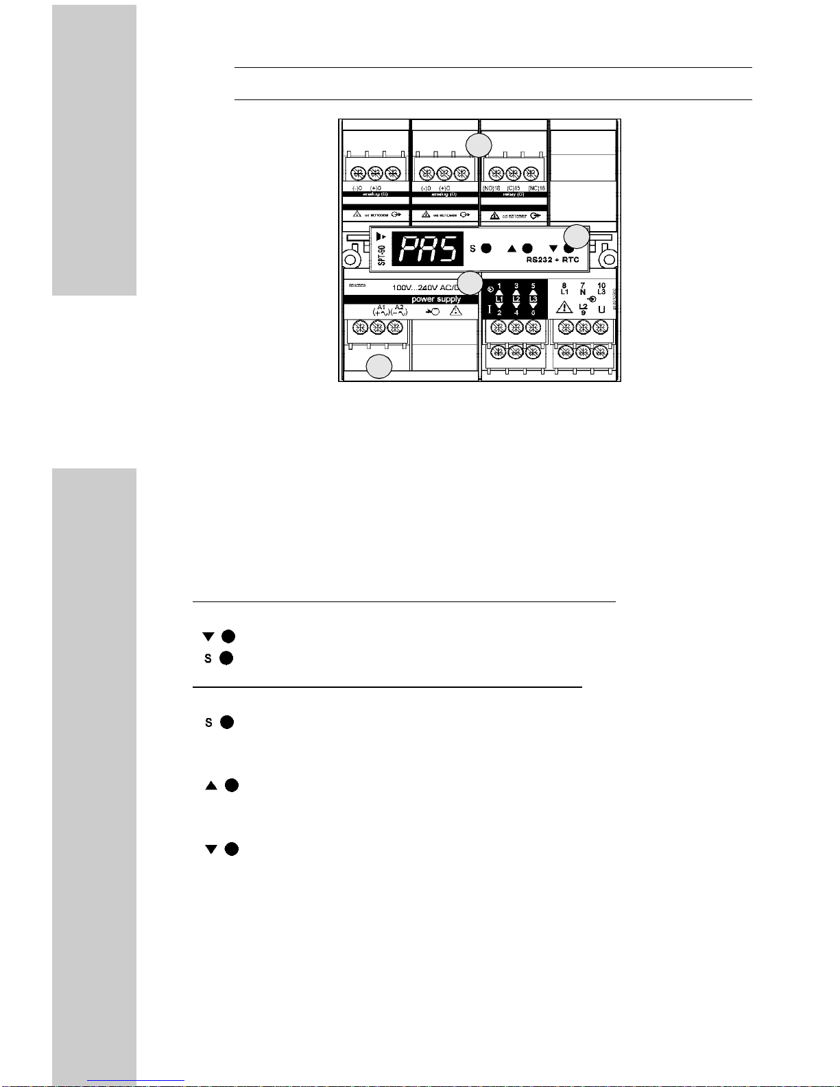
POWER SUPPLY INPUT
From 90 to 260VAC/VDC, 50/60 Hz;
From 18 to 60VAC/VDC, 50/60 Hz;
Self-consumption: ≤30VA / 20W (from 90 to 260V)
≤ 20VA / 20W (from 18 to 60V)
OPERATING TEMPERATURE
: from 0 to +50°C (R.H. < 90% non-condensing)
STORAGE TEMPERATURE
: from –10 to +60°C (R.H. < 90% non-condensing)
REFERENCE VOLTAGE FOR THE INSULATION: 300VRMS to earth
INSULATION: 4000VRMS between all outputs/inputs to ground
DIELECTRIC STRENGTH: 4000VRMS for 1 minute
NOISE REJECTION (CMRR): 100 dB, from 48 to 62 Hz
ACCORDING TO THE FOLLOWING STANDARDS:
Electromagnetic compatibility: EN 50 081-2, EN 50 082-2
Safety: IEC 61010-1, EN 61010-1
Product: IEC 60688-1, EN 60688-1
Pulse output: DIN 43864

5
ENGLISH
CONNECTIONS: screw-type. Max. 2.5 mm2wire (x2)
DIMENSIONS: 90 x 90 x 140 mm
MATERIAL: ABS, self-extinguishing: UL 94 V-0.
PROTECTION DEGREE: IP 20
WEIGHT: 550 g. approx. (packing included).
INSTALLATION
Overall dimensions and panel cutout
138mm
Mounting
The instrument is to be mounted on DIN-rail.
Connections
See the wiring diagrams on the appendix.

6
ENGLISH
Position of the slots and relevant modules
12
ABCD
PU
PS IM
DESCRIPTION A B C D PU PS
IM
Singleanalogueoutput • •
Dualanalogueoutput • •
RS485serialoutput •
RS232serialoutput •
Programmingmodule •
Singlerelayoutput • •
Dualrelayoutput • •
Singleopencollectoroutput • •
Dualopencollectoroutput • •
Digitalinputs •
Powersupply •
Measuringinputs •

7
ENGLISH
PRELIMINARY OPERATIONS
Before supplyingtheinstrument,makesurethatthepowersupplyvoltage
correspondstowhatisindicatedonthelaterallabeloftherelevantmodule.
For example:
AP1020
Universal power supply
100V...240V DC/AC (50Hz to 60Hz)
input range
12W / 30VA 1 PHASE
power consumption
S/N 001900/20115
serial number
WARNING: the measuring input module is fixed and sealed to the
main unit of the instrument. Its removal implies the breakage of the
seal with subsequent expiry of the warranty.
The various modules (input, output and power supply) have been con-
ceived to be mounted only in one of all the slots available.
Toknowin whichslotevery moduleisto bemounted,refer tothedrawing
on the previous page.
Foracorrectmountingoftheinstrument, insertthemodulesintherelevant
slots, then, at the end, enter the central module, which is a blind module
oraprogrammingkey-padora communicationportRS232andwill fix the
other modules in the relevant slots. To remove the modules, use a
screwdriver:
A) lever the two fixing tabs (points “1” and “4” in the drawing below)
B) extract the central module,
C) remove also the other modules.
NOTE: any slot which has not been used must be closed by means of
the special plug modules.
Screwdriver

8
ENGLISH
FRONT PANEL DESCRIPTION
Note:the keyboard+displaymoduleforparameterprogrammingmaynot
bepresentontheinstrument:inthiscase,theRS232serialoutputmodule
or a plug module (without any function) can take its place.
1. Keyboard
The keyboard module (when present) allows to access to the following
functions:
Functions available out of the programming phase.
Keys to be pressed:
Displaying of the revision number (example: r. 0), for a few seconds.
For more than two seconds: access to the programming phase.
Functions available in the programming phase.
Keys to be pressed:
Password confirmation.
Access to the main menu and to the secondary menus;
Inthesecondarymenus:valuesettingandexitfromthesecondarymenu.
Increase of the password value.
Inthemainmenu: selection oftheparameters(from the firsttothelast).
In the secondary menus: increase of the displayed value.
Decrease of the password value.
Inthemainmenu: selection oftheparameters(from the lasttothefirst).
In the secondary menus: decrease of the displayed value
2. Display
Alphanumeric indication by means of a 7-segment LED:
• of the programming parameters;
• of the alarm status.
3. Terminal blocks
3
2
1
3

9
ENGLISH
OPERATING MODE
It is possible to configure SPT-90 either by means of a special configura-
tion software "SptSoft" or by means of a special programming module:
• Displaying and control (if the programming module is present)
Duringtheoperatingphase,thefollowingstatusindicationsmaybedisplayed:
•the decimal point of the digit on the right is blinking: the
transducer works regularly and it's not in alarm status;
•
theuppersegments ofthe3digitsare blinking:theoperator has
set a high alarm set-point and the instrument is in alarm status;
•the lower segments of the 3 digits are blinking: the operator has
set a low alarm set-point and the instrument is in alarm status.
•the central segments of the 3 digits are blinking; the static
output has been activated by means of the serial interface.
• Programming
Toentertheprogrammingphase,pressthe keyuntil"PAS"isshown
on the display; then "0" will be displayed: the correct numerical code
(password) is to be selected now. The following conditions may occur:
1) theoperatorhasn'tenteredanypassword:pressthe keytoenterthe
configuration menu of the transducer;
2) the operator has already entered a Password: select the correct
password by means of the key (to increase the displayed value)
or (to decrease it) until the desired value is displayed.
Pressthe key toconfirmthevalue;ifthepasswordiscorrect,thenthe
displaywillshow"P.CH"thatisthefirstconfigurationmenu;ifthepassword
isnotcorrect,thedisplayshows"End"andthetransducergoesbacktothe
displaying and control phase.
PROGRAMMING OF A NEW PASSWORD AND AUTOMATIC SELEC-
TIONOF THEPROTECTIONLEVELOFTHECONFIGURATIONDATA.
To enter the new Password:
•if the Password is "0", when the display shows the "P.CH" message,
followed by "oLd" and then "0", select the desired numerical code using
the or keys,thenconfirmitbypressing the key:thedisplay
will show the first configuration menu "P.CH".
•if the Password has already been entered, it is possible to modify it
following the procedure described at No. 2); after the "P.CH" message,
the display shows "oLd" followed by the already programmed value;
select the new numerical code using the or keys and confirm
it by pressing the key: the display will show the first configuration
menu "P.CH".
Data protection levels:
•if the Password is "0", the configuration data are not protected by
undesired accesses;

10
ENGLISH
•if thePasswordisanumberbetween"1 and499",theconfigurationdata
are almost entirely protected against undesired accesses.
It is possible to reset the Password by entering the number 682.
•All programming/configuration steps of the transducer are shown
intheflowchartinthecentreofthismanual.Theflowcharthasbeen
conceivedtomaketheoperatorbetterunderstandtheprogramming
structure of the transducer indicating the position of the current
function with regards to the others. The flow chart also makes the
commands to be used in the configuration phase more easily
understandable.
•Seethechapter"FrontPanelDescription"forallinformationregard-
ing the use of the key-pad and the relevant main functions.
• Description and use of the displayed symbols:
(thesymbolslike PAS inablackbackgroundbelongtothemainmenu;
the symbols like P-S in a white background belong to the secondary
menu).
PAS :access password to programming.
Programmable value: 0 ≤PAS ≤499.
P.CH :selection menu to modify the password
Programmable value: 0 ≤oLd ≤499.
SYS :selection menu of the electrical system (active only if the
transducertakesmeasurementsonsinglephaseorthree-phasesystems
with balanced load). Programmable value:
Selection System type
1 P Single phase
3 P Three-phase, balanced load
in.C :selection menu of the current input/s.
P-S : programming of the (primary/secondary) current transformer/s
ratio.
Programmable value: 1 ≤P-S ≤999.
Example:aCTwitha100Aprimaryanda5Asecondary(100/5A)means
a ratio (P-S value) equal to 20.
in.U : selection menu of the voltage input/s.
d.P : selection of the decimal point position when considering the
voltage transformer/s (V.T.) ratio.
decimal Point Selection Min. value Max. value
111 1 999
11.1 0.1 99.9
1.11 0.01 9.99

11
ENGLISH
P-S:programmingofthe(primary/secondary)voltagetransformer(V.T.)
ratio.
Programmable value: 1 ≤P-S ≤999
Example: a V.T. with a 660V primary and a 100V secondary (660/100V)
means a ratio (P-S value) of 6.6. The position of the decimal point has
beenpreviouslyselectedas11.1toperformaV.T.ratiofrom0.1to99.9.
Ao.0 :selection menu of the digital output.
rEt : selection of the measurement to be retransmitted:
Selection Measurement
r1 System's active power (W)
r2 System's apparent power (VA)
r3 System's reactive power (VAr)
r4 Average active power (Wavg)
r5 System's power factor (cosϕ)
r6 Maximum current (A max.)
r7 Average phase-phase voltage
r8 Phase-neutral voltage-phase 1
r9 Phase-neutral voltage-phase 2
r10 Phase-neutral voltage-phase 3
r11 Frequency-phase 1
Lo.A : programming of the minimum electrical scale of the analogue
output. Value to be expressed as % of the output range (20mA, ±20mA,
±10mA,±5mA,10V,±10V,±5V,±1V)tobegeneratedincorrespondence
withtheminimummeasuredvalue(Lo.Eparameter).Valueprogramma-
ble within the range:
0.0 ≤Lo.A ≤99.9.
Example: (0/20mA output) “Lo.E” = 0kW that must correspond to an
output signal of 4mA.
“Lo.A” (%) = 100 x?mA
20
thatinourexamplecorrespondsto100x4mA/20=20%;thenenter20.0.
Example: (0/10V output) “Lo.E” = 0kW that must correspond to a
retransmitted signal of 1V.
“Lo.A” (%) = 100 x?V
10
that in our example corresponds to: 100x1V/10 = 10%; then enter 10.0.
Example: (±10V output) “Lo.E” = -100kW that must correspond to a
retransmitted signal of -10V.
“Lo.A” (%) = 0
that in our example corresponds to an output of -10V when we have the
minimum of the range as electrical input.

12
ENGLISH
Hi.A : programming of the maximum electrical scale of the analogue
output.
Value expressed as % of the output range (20mA, ±20mA, ±10mA,
±5mA,10V,±10V,±5V,±1V)tobegeneratedincorrespondencewiththe
maximum measured value (Hi.E parameter). Value to be programmed
within the range: 0.0 ≤Hi.A ≤99.9.
Example: (0/20mA output) “Hi.E”= 100kW that must correspond to a
retransmitted signal of 18mA.
“Hi.A” (%) = 100 x?mA
20
that in our example corresponds to: 100x18mA/20 = 90%; then enter
90.0.
Example (0/10V output): “Hi.E ” = 100kW that must correspond to a
retransmitted signal of 5V.
“Hi.A” (%) = 100 x ?V
10
that in our example corresponds to: 100x5V/10 = 50%; then enter 50.0.
Alsointhiscaseitispossibletoinvertthescale,thatis,adecreasingvalue
of the retransmitted signal may correspond to an increasing value of the
input variable.
Example (±10V output): “Hi.E” = 100kW that must correspond to a
retransmitted signal of 5V.
“Hi.A” (%) =100- 100 x 5V
20
that in our example corresponds to: 100-(100x5V/20) = 75%; then enter
75.0
Lo.E:programmingoftheminimumelectricalscaleofthemeasurement
(Lo.E is connected to the output value Lo.A). This value is preceded by
a symbol indicating the multiplier of the measured parameter. The
multiplier's symbol corresponds to the values indicated in the following
table:
Symbol Multiplier
none 1
K1000
M1000000
Moreover,thedisplaywillshowthedecimalpointcorrespondingtothefull
scale.Asa result, theprogrammablevalue, excludingthedecimal point,
will be as follows: -999 ≤Lo.E ≤999.
Note.Shouldoneormoreoftheprecedingretransmittedmeasurements
havebeenmodified,thenthedisplayedvaluewillbe"000",otherwisethe

13
ENGLISH
VARIABLE Standard HiE
r1 - System's active power (W) HiE = VL-N * VT * Dp * IN* CT * PH
r2 - System's apparent power (VA) HiE = VL-N * VT * Dp * IN* CT * PH
r3 - System's reactive power (var) HiE = VL-N * VT * Dp * IN* CT * PH
r4 - Average active power (Wavg) HiE = VL-N * VT * Dp * IN* CT * PH
r5 - System's power factor HiE = L.00
r6 - Maximum current HiE = IN* CT
r7 - Phase-phase average voltage HiE = VL-L * 3 * VT * Dp
r8 - Phase-neutral voltage phase 1 HiE = VL1-N * VT * Dp
r9 - Phase-neutral voltage phase 2 HiE = VL2-N * VT * Dp
r10 - Phase-neutral voltage phase 3 HiE = VL3-N * VT * Dp
r11 - Frequency phase 1 HiE = 100
IN= rated current
PH= number of phases
DP= multiplying value of the decimal point (1, 10 or 100)
display will show the value set during the last programming.
At the first switching on, the value of "Lo.E" is automatically set to "0" by
the transducer. This value can be changed in order to have a different
beginning of scale corresponding to the "Lo.A" analogue output.
Hi.E:programmingofthemax.electricalscaleofthemeasurement(Hi.E
isconnectedtotheHi.Aoutputvalue).Thisvalue isprecededbythesame
symbol indicating the multiplier of the measured variable as per "Lo.E";
also the decimal point is the same as per "Lo.E".
The value of "Hi.E" is to be higher than "Lo.E" of at least 50 digits.
Programmable value: Lo.E + 50 ≤Hi.E ≤999.
"Hi.E" is normally calculated by the transducer in accordance with both
CT and VT ratios (see table below). If necessary, this parameter can be
changed in order to have a lower/higher full scale corresponding to the
"Hi.A" of the analogue output.
Note. Should one or more of the preceding values (that is CT ratio, VT
ratio,selectionofthemeasurement,Lo.A,Hi.A)havebeenmodified,then
the displayed value will be calculated according to the full scale of the
transducer multiplied by the CT and VT ratios; if none of the previous
variables has been modified, then the display will show the previously

14
ENGLISH
programmed value.
Example 1: thetransduceris athree-phasemodelforunbalancedloads
and requires a rated input of a 100/š 3V phase-neutral voltage and 5A
current (AV3.3 model). The mains is 20,000V phase-phase voltage and
the maximum current for each phase is 500A. Therefore, the relevant
parameters become:
in.C →P-S = 100;
in.V →d.P = 111 (no decimal point) →P-S = 200.
The analogue output “OUTPUT 1” is a 4-20 mA (Lo.A = 20.0%, Hi.A =
99.9%) and the selected retransmitted measure is "r1" (system's active
power).Theautomaticcalculationofthefullscalemadebythetransducer
is 20,000 / š3x 500 x 3 = 17.3MW (VÐ / š3 x I max. x N° of phases).
Prior to the setting of "Lo.E", the display will show the segment close to
"M" (mega), which will be blinking, followed by 00.0. The same segment
will appear for "Hi.E" followed by 17.3 (full scale value). The analogue
output value will be 4mA when the power is equal to 0 and 20mA when
the power is 17.3 MW.
Example 2: The mains is 10kV phase-phase voltage. With the same
proceduredescribedinexample1,selectthe"r7"measurement(average
phase-phase voltage). The "Lo.A" value will be set at 80.0 (80% of the
outputfullscale=16mA) andthe"Hi.A"valueat20.0(20%ofthefullscale
=4mA).Priorto "Lo.E"and"Hi.E",thedisplayshowsthe"–" ontheright
(indicating K) that will be flashing and the "00.0 and 10.0" values
respectively will be set. In this case the value of the analogue output will
be 4mA with a 10kV input, and 16mA with an input voltage equal to 0
(scale inversion).
Note: retransmission of the measured system's power factor (cosϕ) . If
the "r5" measurement is selected, the electrical parameters "Lo.E" and
"Hi.E"displaythe type ofpowerfactor displacement which hasbeenset
("C" capacitive or "L" inductive) followed by the decimal point and by the
first two decimal numbers of the power factor.
Example: C.21 stands for a capacitive power factor the value of which is
0.21 and L.73 stands for an inductive power factor the value of which is
0.73. The only exception is the unit power factor which will be displayed
as "1.00".
A.o1: selection menu of the additional analogue output (if available).
Theprogrammingstepsarethesameasthoserelatingtooutput0"Ao.0".
S.ou : selection menu of the serial communication output (if available).
Thetransducerisprovided witha serialinterface(onrequest)thatallows
the communication with a PC or a PLC. It is possible to retransmit both
thestaticand the dynamicvariablesand to makeconnectionswith more
than one transducer (multidrop).

15
ENGLISH
Add : programmable address value: 1 ≤Add ≤255.
b.dr : programming of the data baud rate:
Selection Value
9.6_ 9600 bit/s
4.8_ 4800 bit/s
2.4_ 2400 bit/s
1.2_ 1200 bit/s
PAr : programming of the parity bit.
Selection Parity
no No parity
EUE Even parity
For any further information on the serial interface, see the relevant
literature (available on request).
out : selection menu of the output working (available only if the open
collector/relay output is present). Set the working of the output in
accordance with the following selections:
Selection Output working
Loc Local (to be used only as set-point/pulse output)
rEn Remote (can be driven only by serial port)
EnE:selectionmenuoftheenergymeasurement(selectableonlyifthe
serialoutputorthepulseoutputarepresent,and"out"hasbeenselected
locally). Programmable values:
Selection Energy
E 1 Active energy (Wh).
The negative energy is not added.
E 2 Apparent energy (VAh)
E 3 Reactive energy (VArh)
E 4 Active energy (Wh).
The negative energy is added with its own sign.
Thesignofactiveenergydependsonthedirectionofthecurrent:positive
ifitisaconsumedenergy;negativeifitisasuppliedenergy.Thereactive
energy and the apparent energy are always positive.
out : selection menu of the output working (selectable only if the static
output is present). The static output must be configured locally in the
"S.ou" menu, otherwise the instrument ignores all the previously set

16
ENGLISH
parameters and the output is activated and deactivated only from a
personal computer's serial port. The transducer displays one of the
following possibilities, depending on the type of card being mounted:
PuL : pulses for energy measurements only.
The number of pulses is set for each energy unit; the latter is defined by
the type of totalized energy chosen in the "EnE" menu (Wh, VAh, VArh)
and by the multiplier, which is identified by a blinking hyphen as for the
"Lo.E" and "Hi.E" parameters. The choice to program the number of
pulses for kWh (or kVAh or kVArh) or for MWh (or MVAh or MVArh) is
madeautomaticallybythetransduceraccordingtotheinstalledpower,if
the latter is more than 2MW the pulses/energy become pulses for MWh
(or MVAh or MVArh).
AL :alarmconnectedtotheselectedmeasurement.Theselectionofthis
measure depends on the choice made in the "AL" secondary menu
according to the "Selection / Measurement" table on page 11.
A.on :valueofthe highalarm.Thisvalue canbesetin accordancewith
theprogrammedHi.E-Lo.E(electrical) inputrange;themaximumrange
is: –999 ≤A.on ≤999.
A.oF
: value of the low alarm. This value can be set in accordance with the
programmed Hi.E - Lo.E (electrical) input range; the maximum range is:
–999 ≤A.of ≤999.
dEL : value expressed in seconds of the time delay at the alarm set-
point'sactivation(ON).Thisvalueistobeprogrammedwithintherange:
0≤dEL≤255;itcanbeusefulwhenitisnecessarytoavoidthealarmset-
point's activation if the alarm duration is not long enough.
Note. The operating mode of the set-point is identified by the values of
the set-point with reference to the following cases:
1.
A.on > A.oF: the alarm occurs when the measured value is higher than
"A.on". The hysteresis is given by the difference between "A.on" and "A.oF".
Thedelay timestartswhenthemeasuredvariablegoes overtheprogrammed
"A.on" value according to what has been already written for "dEL".
2.
A.on = A.oF: the alarm occurs when the measured value is equal to
"A.on". There isn't any hysteresis and the "dEL" delay time starts when the
measuredvariablegoesovertheprogrammed"A.on"valueaccordingtowhat
has been already written for "dEL".
3.
A.on<A.oF:thealarmoccurswhenthemeasuredvalueislowerthan"A.on".
The hysteresis is given by the difference between "A.oF" and "A.on".
The "dEL" delay time starts when the measured variable goes under the
programmed "A.on" value according to what has been already written for
“dEL”.
Example 3: if an alarm is to be activated when the power factor goes
below cosϕ0.75 inductive with an hysteresis equal to 0.1 and a delay of
20 seconds (according to what has been written for A.on > A.oF), select

17
ENGLISH
“r5” in the “AL” secondary menu and set the parameters as follows:
A.on = L.75, A.oF = L.85, dEL = 20.
Example4:ifanalarmistobeactivatedwhentheactivepowergoesover
135kW, with an hysteresis equal to 8kW, and a delay of 10 seconds
(accordingtowhathasbeenwrittenforA.on>A.oF),thenselect"r1inthe
“AL” secondary menu and set the parameters as follows:
A.on = 135, A.oF = 127, dEL = 10.
FiL : selection menu of the digital filter's parameters.
This function allows you to stabilize the value of the instantaneous
measurement retransmitted by the transducer when the value is not
stable enough from the beginning and will not therefore allow either a
clearreadingontheinstrumentsconnectedtotheoutputoragoodcontrol
by the alarm set-point.
Fi.S : activation range of the digital filter.
This value is programmed within the range: 0 ≤Fi.S ≤99.9. The
programmable numerical value represents the fluctuation range (ripple)
of the value which has been measured and retransmitted by the trans-
ducer.Inthefirstconfigurationphasethis valuemust beequalto"0"and
the right value is to be entered only after the verification of the possible
fluctuation. The value of this parameter can be calculated by the below
indicatedformulaorenteredstepbystepaftercheckingtheoutputripple.
The formula to be used is the following:
Ripple (%) = 100.000 x ∆R x (Hi.E - Lo.E)
AFS x FSO (Hi.A - Lo.A)
where:
AFS = electrical full scale value "Hi.E" automatically calculated by the
transducer;
FSO = maximum full scale of the analogue output (20mA, 10V, etc.);
∆∆R= fluctuation of the analogue output value (mA or V);
Hi.E = maximum manually programmed electrical scale value;
Lo.E = minimum manually programmed electrical scale value.
IftheLo.EandHi.Eparametershavenotbeenchangedfromtheoriginal
(Lo.E = 0, Hi.E = AFS), the formula becomes:
Ripple (%) = 100.000 x ∆R
FSO (Hi.A - Lo.A)
Note:
if the "Hi.E" parameter has been changed and the operator doesn't
remember the original value (the one which is automatically calculated by
the transducer) it can be displayed again by changing the actual "rEt"
parameterwithanyother parameter, confirming thenewselection (fromr1
to r11) with the “S ” key and subsequently entering the “rEt” secondary
menu, this time selecting the desired measure. The value subsequently
displayedbythe"Hi.E"parameterwillbethevalueautomaticallycalculated
by the transducer (AFS). Example: if the fluctuation of the analogue output
is 0.5mA (ÐR), which is the ripple calculated to be entered as Fi.S value?

18
ENGLISH
Considering:
AFS = 37.5 (kW), FSO = 20mA,
Hi.E = 28.0 (kW); Lo.E = 10.0 (kW), Hi.A = 99.9 (%), Lo.A = 20.0 (%)
the Ripple (%) becomes: 100,000 x 0.5 x (28 - 10) = 15 (%)
37.5 x 20 (99.9 - 20)
then, enter 15.0 as Fi.S value.
Fi.C:valueofthefilteringcoefficienttobeprogrammedwithintherange:
1 ≤Fi.C ≤255.
The higher is the "Fi.C" value, the higher the filtering of the measured
valueandthelongertheupdatingoftheanalogueoutput/sandalarmset-
point.
Note:foracorrectworkingofthefilter,therelevantcoefficientmustsatisfy
the following relationship: 1≤Fi.C ≤(Fi.S x 4) ≤255.
P.it : selection menu of the active power integration time.
Every "t"minutes,the output isupdatedas an averagecalculationof the
instantaneous active power measured during the latest time period (t).
Setting of the integration time expressed in minutes. Programmable
value: 1 ≤t ≤30.
End :exit from programming.
The exit from programming can occur also for time-out after approx. 20
secondsfromthelastoperation.Thedisplaywillthenshowonlyablinking
point (if it's not an alarm).
Warning. Whentheinstrumentexitsfrom programmingdue totime-out,
thelastparameter whichwasbeing programmedwillnotbesaved inthe
EEPROM memory.
Note. Displaying of numbers: the range of numbers which can be
displayed by the transducer goes from –999 to +999 (except for the
decimal point).
The negative numbers (which may be displayed for some parameters
such as "Lo.E", "Hi.E", "A.on" and "A.oF") are identified by a blinking
decimal point of the least significant digit.
SptSoft
SptSoft is a software which can be used to easily load and unload the
programming parameters from an SPT-90 to a PC and from a PC to a
single SPT-90 or a series of them connected in a network.
The software can also be used to control the communication in the
network itself.
To install the software insert disk N° 1 in the PC and from the "Start-up" menu
ofWindowsselect"Execute...".Then,type"A:\setup"inthecommandbarand
then click on "OK" and carry out the instructions on the screen.
Once you run the software, the screen shows the main window of the
programme(seefigureonthefollowingpage)whereitispossibletoread
and then modify the programming parameters of the instruments con-
nected to the network.

19
ENGLISH
ACCURACY INFORMATION
WARNING
The control of the analogue outputs is not guaranteed if:
-theoverloadconditions oftheinputs(1.2In/Un)areexceededand
- the "Sr" scale ratio is higher than 4.
Input Star Voltage Delta voltage Current
AV1 Un: 100V/š3 Un: 100V In: 1A
AV3 Un: 100V/š3 Un: 100V In: 5A
AV4 Un: 250V Un: 430V In: 1A
AV5 Un: 250V Un: 430V In: 5A
AV7 Un: 400V Un: 690V In: 5A
PN /PIAccuracy class of the transducer as
a relation of PN/PI and PF (cosϕ)ϕ) Trend of the E error depending on
the SR scale ratio
SR
E %
80° 70° 60° 50° 40° 30° 20° 10° 0° ϕ
0.34° 0.64° 0.86 0.98 cosϕ
0.17° 0.5° 0.76° 0.94° 1°
0.8
1.0
0.4
0.2
0.5
0.5 11.5 22.5 33.5 4
0.5 *
1.0 **
1.5
0.2
0.4
0.6
0.8
1.0
1.2
1.4
* V = 0.9 to 1.1Un; I = 0.6 to 1In; f = 48 to 62 Hz
** V = 0.7 to 1.2Un; I = 0.2 to 1.2In; f = 48 to 100 Hz

20
ENGLISH
PN:
PN= UNx I x PF (cosϕ) (single-phase system);
PN= š3 x UNx I x PF (cosϕ) (three-phase, three-wire system);
PN= 3 x UNx I x PF (cosϕ) (three-phase, four-wire system);
where:
UN= the real phase-neutral voltage of the electrical system being
measured;
I=themaximumphasecurrentoftheelectricalsystembeingmeasured;
Power factor (cosϕ) = the average power factor (cosϕ) of the electrical
system to be measured;
PI :
PI= UI x IIx VT (ratio) x CT (ratio) (single-phase system);
PI= š3 x UI x IIx VT (ratio) x CT (ratio) (three-phase, three-wire system);
PI= 3 x UI x IIx VT (ratio) x CT (ratio) (three-phase, four-wire system);
where:
UI = rated input voltage of the transducer; it changes depending on the
model (see table on page 19);
II= rated input current of the transducer; it changes depending on the
model (see table on page 19);
VT (ratio) = the value of the voltage transformer ratio (P-S parameter in
the "in.U" menu);
CT(ratio)=theratedvalueofthecurrenttransformerratio(P-Sparameter
in the "in.C" menu);
Example 5:
model AV3.3 (3-wire system)
UN = 6kV (Ð voltage)
I = 265A (single phase current)
Cosϕ = 0.85 (system's power factor)
UI = 100V;
II = 5A
VT (ratio) = 6kV = 60 CT (ratio) = 300A = 60
100V 5A
PN becomes: š 3 x UN x I x cosϕ = š 3 x 6000 x 265 x 0.85 = 2.33MW
PI becomes: š 3 x UI x IIx VT (ratio) x CT (ratio) = š 3 x 100 x 5 x 60 x 60
= 3.12MW, the ratio PNis: 2.33 = 0.75
PI3.12
Example 6:
model AV3.3 (4-wire system)
UN = 6kV / š 3;
I = 265A
Power factor (Cosϕ) = 0.85
UI = 100V / š 3
II = 5A
VT (ratio) = 6kV / š 3 = 60 CT (ratio) = 300A = 60
100V / š 3 5A
Table of contents
Other CARLO GAVAZZI Transducer manuals
Popular Transducer manuals by other brands

Garmin
Garmin Panoptix PS21-TR installation instructions

Omega
Omega PX276 instruction sheet

controlair
controlair 500-AA Installation, operation and maintenance instructions

MG
MG LTRPN instruction manual

Veris Industries
Veris Industries Hawkeye 922 installation guide

Balluff
Balluff MICROPULSE+ BTL7-A501-M Series user guide

Endress+Hauser
Endress+Hauser Cerabar T PMC131 operating instructions

halstrup-walcher
halstrup-walcher P29 Original instruction manual

Airmar
Airmar M260 Owner's guide & installation instructions

Soundmask
Soundmask SM-TC-1265 operating manual

HBM
HBM C4 Mounting instructions

Camille Bauer
Camille Bauer SINEAX DME 406 operating instructions