CARNES HXHAF User manual

READ AND SAVE
THESE INSTRUCTIONS
RESIDENTIAL HUMIDISTAT
OWNERS MANUAL AND
QUICK REFERENCE GUIDE
MODEL HXHAF
FORM 16763
ISSUED: 07-31-20

CAUTION:
Follow all recommendations, instructions and precautions in this Installation,
Operation and Maintenance Manual to maximize performance, maintain
efficiency and to provide a safe operational environment. Do not install, use
or operate this equipment until this manual has been completely read and
understood.
Important Note:Disconnect electrical power to the furnace and humidifier
before servicing or starting installation.
Liability:
Carnes does not accept any liability for installations of humidifier
equipment installed by unqualified personnel, or the use of parts,
components, equipment, or alterations of Carnes manufactured equipment
that is not authorized or approved by Carnes.
2 Form 16763
Safety Cautions | RESIDENTIAL HUMIDISTAT
!

RESIDENTIAL HUMIDISTAT | Table of Contents
Form 16763 3
Model HXHAF............................................................................................. 0
Caution........................................................................................................ 2
Packing List................................................................................................. 4
Humidistat Function .................................................................................... 4
Complete Installation .................................................................................. 5
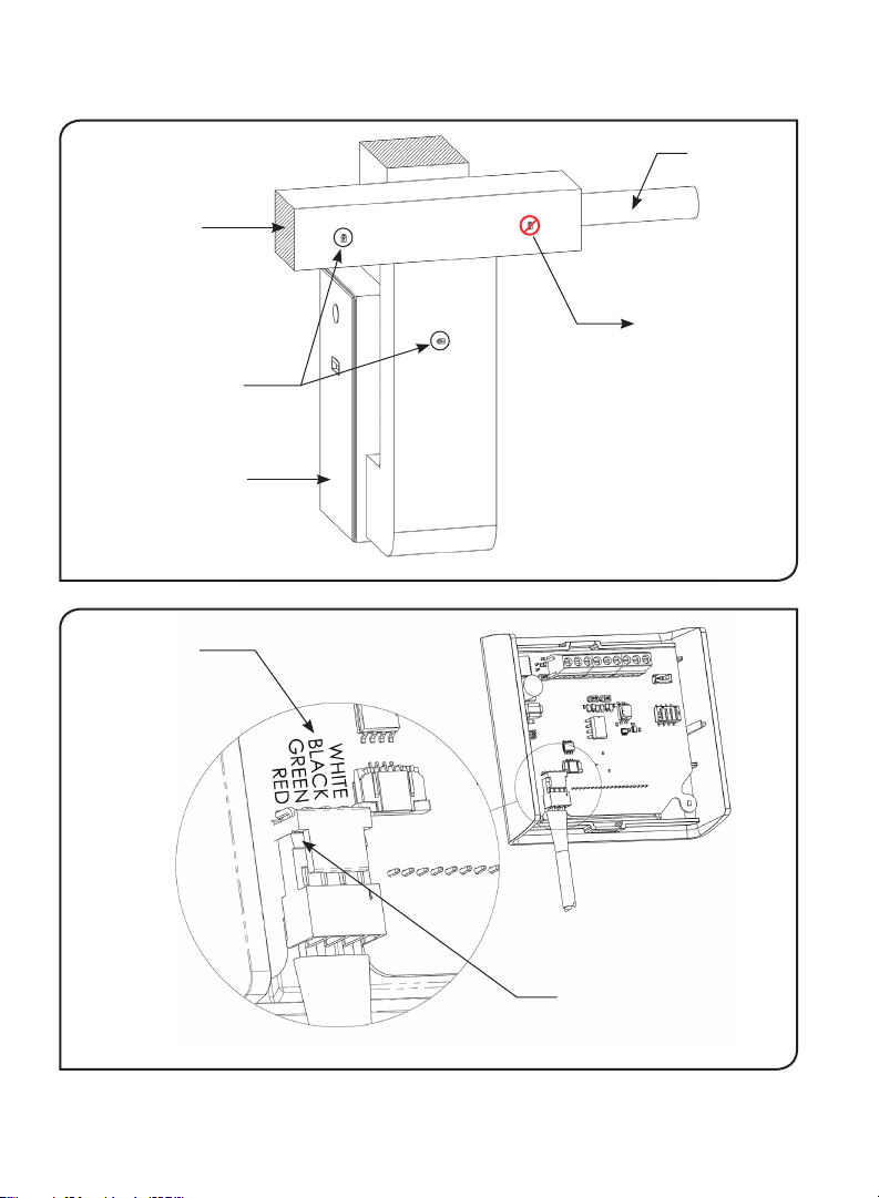
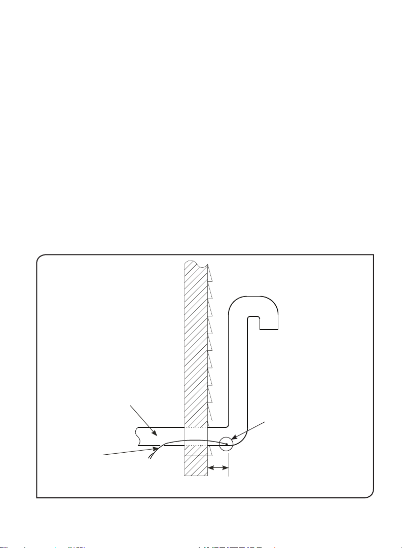
Duct Installation.................................................................................... 5
Wall Mount Installation ......................................................................... 7
Outdoor Temperature Sensor .............................................................. 7
Location Outdoors.......................................................................... 8
Location in Outdoor Air Intake ....................................................... 9
Wiring ................................................................................................. 10
Power Connection Wiring (R, C) ................................................. 10
Outdoor Temperature Sensor Wiring (ODT) ............................... 10
Heat Signal Wiring (W) ................................................................ 10
Automatic External Fan Control Wiring (G, GF) .......................... 10
Humidifier Control Wiring (H1+, H2-)........................................... 10
Wiring Notes/Cautions ................................................................. 11
Operation .................................................................................................. 12
Screen and Menu............................................................................... 12
Home Screen ............................................................................... 12
Fan/Heat Signal Indicators .......................................................... 13
Menu ............................................................................................ 14
Setpoint Adjustment Page ........................................................... 15
Mode Selection Page................................................................... 15
Modes of Operation .................................................................................. 16
General Function................................................................................ 17
Heat-Only Mode ................................................................................. 17
Basic Mode (fan wiring required for this mode - G, GF).................... 17
Eco Mode (fan wiring required for this mode - G, GF........................ 17
Performance Mode (fan wiring required for this mode - G, GF) ........ 17
Factory Default ................................................................................... 18
1-Wire Control........................................................................................... 18

Packing List | RESIDENTIAL HUMIDISTAT
4 Form 16763
Humidistat Function
A humidistat is a device that measures relative humidity and works with a
home’s heating and cooling system to automatically control a humidier to
maintain a desired humidity level throughout the home.
The CARNES HXHAF residential humidistat is capable of controlling a
humidier by ON/OFF or modulating 0-10 VDC control signals. The humidistat
offers four modes of operation to t any humidication need. The four modes
include Performance, Eco, Basic and Heat-Only Mode.
The humidistat is preset to Heat-Only Mode and ON/OFF control. These
settings are the basic setup for most homes and no adjustment is needed to
function with your Carnes humidier out of the box.
In winter climates it is highly recommended to install the provided
outdoor air temperature sensor. This minimizes condensation on
windows and in the structure when temperatures are cold. If the sensor is
not installed in winter climates the user will be required to manually adjust
the humidistat setpoint based on Table 1 or risk damage due to excess
humidity and condensation.
Verify all components were included
in the humidistat packaging.
A. Humidistat
B. Duct Sensor
C. Outdoor Air Temperature Sensor
D. Sheet Metal Screws (3)
E. Drywall Anchors and Screws (2 each)
A
BC
Humidistat Package Components

RESIDENTIAL HUMIDISTAT | Installation
Form 16763 5
Humidistat Option 1 — Return Duct
1. Choose a location on the return air
duct to mount the duct sensor. See
Figure 2 for location options. Make
sure the humidistat mounting
location is close enough to plug in
the sensor. Install the sensor a
minimum 6 inches ahead of or a
minimum 15 inches after a
change in airow direction or
obstruction in the duct. Do not
install duct sensor near outdoor
air intake.
2. Drill a ½ inch hole in the duct to
place the sensor. Use a sheet metal
screw (D) to attach sensor to the
duct. Arrows in duct mount sensor indicate the direction the airow
should pass over the sensor for optimal readings (Figure 1).
3. Mount the humidistat to a wall or duct in a convenient location that
allows easy adjustment to the settings. To mount the humidistat,
remove the back plate and install with screws (D or E) through the
mounting holes.
4. Plug the duct sensor into the humidistat. Pay close attention to the
orientation of the plug or permanent damage will occur to the
sensor. See Figure 3 for proper orientation of the duct sensor plug.
Place the hook of the red plug up away from the circuit board and push
onto the white connector in the bottom left corner. The wire colors are
also marked on the circuit board and match the correct orientation of
the plug wires.
Airow
Figure 1: Duct Sensor

Installation | RESIDENTIAL HUMIDISTAT
6 Form 16763
Figure 2: Duct Sensor Location
Figure 3: Duct Sensor Connection
Hook Up Away From
Circuit Board
Wire Colors
Return Duct
Locations for
Duct Sensor
Outdoor
Air Intake
Too Close
To Outdoor
Air Intake
Furnace

RESIDENTIAL HUMIDISTAT | Installation
Form 16763 7
Humidistat Option 2 — Wall Mount
1. Select a location in the living area of the residence. Typically the
humidistat will be placed on the wall near the main thermostat.
2. The humidistat should be placed in an area of sufcient air movement
and out of the way of any other temperature or humidity affects. For
example, do not place the humidistat in direct sunlight, near windows,
or near an air register.
3. Once the location is selected, attach the humidistat back cover to the
wall using 2 screws/anchors (E).
Note: The duct sensor is not needed for this installation option.
Outdoor Temperature Sensor
When outdoor air temperature is very low condensation can occur on
windows and other surfaces which may cause damage to the house. To
minimize this risk the outdoor air temperature sensor should be installed, which
lowers the humidity setpoint to a safe level where the indoor relative humidity is
too low to condense. The outdoor temperature compensation controls adjusts
humidity according to the values in Table 1. The humidistat will automatically
detectiftheoutdoorairtemperaturesensorisconnectedand controltherelative
humidity setpoint accordingly.

Installation | RESIDENTIAL HUMIDISTAT
8 Form 16763
Outdoor Temperature Sensor Option 1 — Outdoors
To mount the Outdoor Temperature Sensor outdoors the signal wire will
need to penetrate an exterior wall. Use the following guidelines for proper
operation of the sensor:
Mount the sensor where:
• there is good air circulation
• wire distance between sensor and humidistat is less than 200 feet
• it can measure true outdoor ambient air temperature
• it is above the expected snow line
Do NOT mount the sensor:
• in direct sunlight
• where it may be covered by debris, snow, or ice
Outdoor Air
Temperature (°F)
Outdoor Air
Temperature (°C)
Adjusted Maximum
Humidity Setpoint
(RH%)
-30 -34.4 10
-20 -28.9 15
-10 -23.3 20
0 -17.8 25
10 -12.2 30
20 -6.7 35
30 -1.1 40
40 4.4 45
45 7.2 47.5
>45 >7.2 Unadjusted
Table 1: Maximum setpoint based on outdoor air temperature

RESIDENTIAL HUMIDISTAT | Installation
Form 16763 9
Outdoor Temperature Sensor Option 2 —
Outdoor Air Intake
Mount the sensor in the outdoor air intake by drilling a 1/4 inch hole within
12” of outside. Angle the hole towards the outside. Insert the temperature
sensor into the intake pipe until the sensor is at least 2” outside the
wall of the house. Seal the hole and secure the wire so it cannot be
accidentally pulled out. See Figure 4 for example installation.
CAUTION: electrical interference can cause erratic system operation.
• Do not route temperature sensor wiring with building power wiring, next
to control contactors, near light dimming circuits, or electric motors.
• Use shielded cable to reduce interference when rerouting is not
possible.
• Be sure wires have a cable separate from the humidistat cable.
• See Figure 5 for wiring diagram.
Figure 4: Outdoor Temperature Sensor in Furnace Intake Pipe
Connect to
Humidistat
(ODT)
Drill Hole in
Pipe & Seal OAT (Outdoor
Air Temperature)
Sensor
2” min.
INSIDE OUTSIDE
Furnace
Fresh Air
Intake

Installation | RESIDENTIAL HUMIDISTAT
10 Form 16763
Wiring
**TURN POWER OFF TO ALL HVAC EQUIPMENT BEFORE WIRING**
Power Connection Wiring (R, C)
• The humidistat controller is powered from the R and C connections
from the furnace and needs continuous power to operate properly.
Proper R and C wiring is shown in Figure 5.
Outdoor Temperature Sensor Wiring (ODT)
• The outdoor temperature sensor wires will connect into the ODT
terminals on the humidistat terminal block as shown in Figure 5.
Heat Signal Wiring (W)
• The W terminal is the heat signal from the thermostat. Wire the W
terminal from the furnace control panel to the W terminal on the
humidistat terminal block as shown in Figure 5.
Automatic External Fan Control Wiring (G, GF)
• Fan control wiring should be completed when possible. If the fan
control wiring is not possible then the humidistat should only be ran in
Heat-Only Mode as described in the Operation section of this
document.
• The wire running from the G terminal on the furnace control board to
the G terminal on the thermostat will need to be disconnected. The G
terminal from the thermostat will then need to be wired directly to the
G terminal on the humidistat terminal block. The G terminal on the
furnace control panel will then need to be wired directly to the GF
terminal on the humidistat terminal block. See Figure 5.
HumidierControlWiring(H1+,H2-)
• The humidier control terminals are labeled on the humidistat as H1+
and H2-. These terminals will need to be wired directly to the humidier
as shown in Figure 5. H1+ on the humidistat terminal connects to the
HUM terminal on the humidier control panel and H2- on the humidistat
terminal connects to the GND terminal on the humidier control
panel.

RESIDENTIAL HUMIDISTAT | Installation
Form 16763 11
R
C
G
Y
W
R
C
G
Y
W
CR ODTODT WGH1 H2 GF
+-
FURNACETHERMOSTAT
CARNES HUMIDISTAT
24
24
HUM
GND
+
-
CARNES
HUMIDIFIER
OUTDOOR
TEMP
SENSOR
(REMOVE)
Figure 5: Humidistat Wiring Diagram
Wiring Notes/ Cautions
• Do not connect duct sensor backwards. Always verify the correct
placement of the duct sensor terminal to the main humidistat board.
• Verify the wiring before powering on.
• Verify that the humidistat output matches the humidier input type
(Figure 6).
o ON/OFF
o Modulating (0-10VDC)
Figure 6: Verify Control Signal Types Match

Operation | RESIDENTIAL HUMIDISTAT
12 Form 16763
Screens and Menu
Home Screen
Figure 7: Humidistat Home Screen
Down Enter Up
Heat Signal is Active
Active Sensor
ROOM
The external duct
sensor is unconnected
and the on-board room
sensor is active
DUCT
The external duct
sensor is connected
and active
Outdoor air temperature
sensor is connected and
active, if unconnected,
outdoor temperature
display will be blank.
Measured
Humidity
User Setpoint
Fan Signal
is Active
Thermostat is
controlling the
blower fan
Humidistat is
controlling the
blower fan

RESIDENTIAL HUMIDISTAT | Operation
Form 16763 13
The humidistat is controlled using touch-sensitive buttons located beneath
the main screen.
The home screen shows measured humidity, user setpoint, and duct or
room temperature. When the duct humidity sensor is installed, the measured
temperature will display “DUCT:” and show the temperature of the duct
sensor. Alternatively, when no duct sensor is plugged into the humidistat
the temperature will display “ROOM:” and display the temperature at the
humidistat.
The outdoor temperature will be displayed when the outdoor temperature
sensor is installed. External fan and heat signals will also be displayed in the
top right-hand corner of the screen when active.
Fan/Heat Signal Indicators
The residential humidistat accepts heat and fan input signals from the
thermostat. When the heat signal is active a moving ame symbol will be
shown in the top right corner of the display screen. When the fan signal is
active a spinning fan icon will appear. A small ‘T’ in the bottom right hand
corner of the fan icon signies that the thermostat is currently in control of
the fan as shown in Figure 7. If the humidistat has activated the fan the icon
will have a small ‘H’ in the bottom right hand corner as shown in Figure 7.

Operation | RESIDENTIAL HUMIDISTAT
14 Form 16763
Settings Page
From the Settings page (Figure 8) the user can select and adjust how they
would like their humidistat to operate. Pressing Enter while on the BACK
selection will take the user back to the previous page.
Pressing the Enter button once will bring up a Settings screen with user
selectable options. Use the Up/Down buttons to navigate the menu and the
Enter button to select and conrm an option.
• The Setpoint Adjustment option on the Settings screen, shown in
Figure 7, allows the user to adjust the desired relative humidity setpoint.
Choosing this option will allow the user to enter the setpoint adjustment
screen.
• The Mode option controls what mode the humidistat will operate in.
Pressing the Enter button while on Mode will take you to the Mode
Selection Page.
• The Units option allows the user to select temperature display units in
Fahrenheit or Celsius. Fahrenheit is the default.
Figure 8: Setting Screen

RESIDENTIAL HUMIDISTAT | Operation
Form 16763 15
Setpoint Adjustment Page
While on this Setpoint Adjustment Page the user can adjust the desired
relative humidity setpoint for the humidied space (shown in Figure 9). The
factory default value of this setting is 45%RH and can be adjusted up or down
depending on user preference. To save the value press the enter button
again. The new humidity setpoint should now be shown on the main screen
(Figure 7).
Mode Selection Page
While on the Mode Selection Page, pressing Enter on any option, besides the
BACK selection, will set the humidistat mode to the selected mode, save the
selection, and bring you back to the Settings Page. Pressing the BACK
selection will keep the previously saved mode and bring you back to the
Settings Page.
Figure 9: Setpoint Adjustment Screen

Operation | RESIDENTIAL HUMIDISTAT
16 Form 16763
Modes of Operation
General Function
The residential humidistat will run the humidier when the duct/room humid-
ity level is below the humidity setpoint and any one of the following is true:
• Heat signal from thermostat is on
• Fan signal from thermostat is on
• Fan signal from humidistat is on
When the humidistat receives an on signal it will control the humidier to
maintain the desired humidity level by ON/OFF or modulating control. ON/
OFF control turns the humidier on when the humidity level drops 10% below
setpoint and turns the humidier off 10% above setpoint. Modulating control
sends a 010 VDC signal to the humidier to proportionally control the steam
output of the humidier.
When the humidier output changes from ON to OFF, the humidistat
will keep the fan running for 90 seconds to prevent excess steam from
condensing in the duct.
Therearefourselectablemodesthehumidistatcanoperateintoprovidethebest
humiditycontrol for any household.Thesemodes can be selectedinthe humid-
istat MODE SELECTION screen (Figure 10) and determine how the humidistat
reacts to the fan and heat signals.
Figure 10: Mode Selection Screen

RESIDENTIAL HUMIDISTAT | Modes of Operation
Form 16763 17
Heat-Only Mode
In Heat-Only Mode the humidistat will only turn on the humidier when
the heat signal from the thermostat is on. This mode works well in winter
climates when humidity is only wanted during the heating season.
Basic Mode (Fan Wiring Required For This Mode, G, GF)
In Basic Mode the humidistat will turn on the humidier when either a fan or
heat signal from the thermostat is on. This mode works well in any climates
that require humidity and in situations where humidity will be needed when
the heat is not running.
*It is recommended that Heat-Only Mode is activated during the summer
months in northern climates to prevent the humidier from running during
the cooling season.
Eco Mode (Fan Wiring Required For This Mode, G, GF)
In Eco Mode the humidistat will turn on the humidier when either a fan or
heat signal from the thermostat is on just like Basic Mode. Eco Mode also
adds the humidistat fan on signal. This will turn on if there has been 2 hours
of no heat or fan signals from the thermostat. The humidistat fan signal
will turn on the furnace fan for three minutes to check the humidity level. If
below the setpoint, the humidistat fan signal will stay on and humidify the
space for a maximum of 1 hour or until a heat or fan signal turns on from
the thermostat. A heat or fan signal from the thermostat will reset the 2 hour
timer. If the humidier cannot meet the humidity needs via the humidier fan
signal the humidistat will revert to Basic Mode to keep the fan from cycling
unnecessarily.
Performance Mode (Fan Wiring Required For This Mode, G, GF)
Performance Mode is for households that desire the most consistent
humidity levels. The humidistat will turn on the humidier when either a fan or heat
signal from the thermostat is on. When the heat or fan signal from the
thermostat turns off, the humidistat will check humidity levels. If the humidity
level is below setpoint, the humidistat fan signal will turn on and humidify the
space for a maximum of 1 hour or until a heat or fan signal turns on from the
thermostat. Performance Mode also incorporates the 2 hour no activity timer
described in Eco Mode. If the humidier cannot meet the humidity needs via
the humidier fan signal the humidistat will revert to Eco Mode to keep the
fan from cycling unnecessarily.

1-Wire Control | RESIDENTIAL HUMIDISTAT
18 Form 16763
Factory Default
Selecting Factory Default will revert the humidistat back to factory settings.
The humidistat will set back to Heat-Only Mode, with a 45%RH setpoint, and
temperature units of Fahrenheit.
1-Wire Control
1-Wire Control requires that the humidistat to be wired correctly to a
smartthermostatorHVACcontroller.1-WireControlmodeallowstheuserto
utilize the humidistat as a control bypass from a smart thermostat. This
function gives control of the humidier to a smart thermostat that has a one wire
humidier control output. When the humidistat operates in this mode, it
discardsanyinternalsetpointsettingsandonlydisplaysmeasuredhumidityand
temperature. If the thermostat sends a signal out for the humidier to run,
the humidistat will accept the signal and turn the humidier on at maximum
output. The humidier will then run until the smart thermostat sends an off
signal to the humidistat.

RESIDENTIAL HUMIDISTAT | Notes
Form 16763 19
___________________________________________________________
___________________________________________________________
___________________________________________________________
___________________________________________________________
___________________________________________________________
___________________________________________________________
___________________________________________________________
___________________________________________________________
___________________________________________________________
___________________________________________________________
___________________________________________________________
___________________________________________________________
___________________________________________________________
___________________________________________________________
___________________________________________________________
___________________________________________________________
___________________________________________________________
___________________________________________________________
___________________________________________________________
___________________________________________________________
___________________________________________________________

This device complies with part 15 of the FCC Rules. Operation is subject
to the following two conditions: (1) This device may not cause harmful
interference, and (2) this device must accept any interference received,
including interference that may cause undesired operation.
448 S. Main St., PO Box 930040, Verona, WI 53593-0040
Phone: 608\845-6411 |Fax: 608\845-6504 |www.carnes.com
Table of contents
Other CARNES Humidifier manuals