MODELS
VCDK090I• VCDK130I• VCDK170I
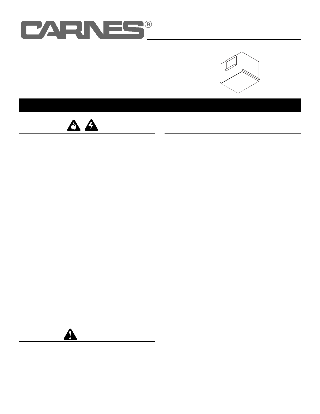
DUCTING
(Vertical blower discharge)
WARRANTY
USE AND CARE
ROOF CAP
12” ROUND
DUCT
12” ROUND
DUCT
9-3/8” x 12-3/4” TO
12” ROUND TRANSITIONS
Typical ductwork connection to a ventilator converted to
right-angle discharge.
Ventilator is designed for continuous operation. If desired, it may
be controlled using an on/off switch or a solid-state, variable
speed control. Follow wiring instructions packed with control,
and adhere to all local and state codes, and the National
Electrical Code.
To clean blower assembly: Disassemble two cabinet halves,
unplug blower from housing, remove blower mounting nuts, and
carefully remove blower from housing. Use appropriate vacuum
attachment or a soft cloth and mild soap or detergent to clean
blower discharge area and wheel. DO NOT ALLOW WATER TO
ENTER THE MOTOR. Make sure blower assembly is complete-
ly dry before reinstalling.
Motor is permanently lubricated. Do not oil or disassemble
motor.
WARNING: To reduce the risk of electric shock,
disconnect from power supply before servicing.
3
Seller warrants products manufactured by it and supplied here-
under to be free from defects in materials and workmanship under
normal use and proper maintenance for a period of twelve months
from date of shipment. If within such period any such products
shall be proved to Seller’s reasonable satisfaction to be defective,
such products shall be repaired or replaced at Seller’s option.
Seller's obligation and Buyer’s exclusive remedy hereunder shall
be limited to such repair and replacement and shall be condi-
tioned upon Seller’s receiving written notice of any alleged
defects no later than 10 days after its discovery within the war-
ranty period and, at Seller’s option, the return of such products to
Seller, f.o.b. its factory, when such return is feasible. Seller
reserves the right to satisfy its warranty obligation in full by reim-
bursing Buyer for all payments it makes hereunder, and Buyer
shall thereupon return the products to Seller. Seller shall have the
right to remedy such defects.
THE FOREGOING WARRANTIES ARE EXCLUSIVE AND
IN LIEU OF ALL OTHER EXPRESS AND IMPLIED WAR-
RANTIES (EXCEPT TO TITLE) INCLUDING BUT NOT LIMITED
TO IMPLIED WARRANTIES OF MERCHANTABILITY FITNESS
FOR A PARTICULAR PURPOSE, PERFORMANCE, OR OTH-
ERWISE, and in no event shall the Seller be liable for claims
(based upon breach of express or implied warranty, negligence,
product liability, or otherwise) for any other damages, whether
direct, immediate, incidental, foreseeable, consequential, or spe-
cial.
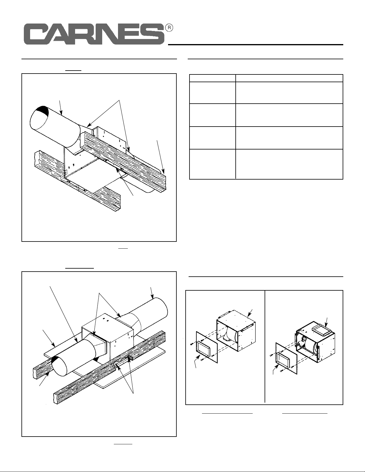
Two ways to connect ductwork to a factory-shipped unit.
DUCTING
(Straight-through blower discharge)
9-3/8” x 12-3/4” TO
12” ROUND
TRANSITIONS
12” ROUND
DUCT
12” ROUND
ELBOW
WALL
CAP
12”
ROUND
DUCT
ROOF CAP