Carotron Trooper Pro User manual

Instruction Manual
Models
TPR902-000
TPR902-E00

2
Table of Contents
1. General Description .......................................................................................................................................... 3
2. Specifications .................................................................................................................................................... 4
2.1 Electrical............................................................................................................................................. 4
2.2 Physical.............................................................................................................................................. 5
3. Installation ......................................................................................................................................................... 6
3.1 Control Installation ............................................................................................................................. 6
3.2 Wiring Guidelines............................................................................................................................... 6
4. Terminal Connections & Functions ................................................................................................................... 7
4.1 AC Power Connections ...................................................................................................................... 7
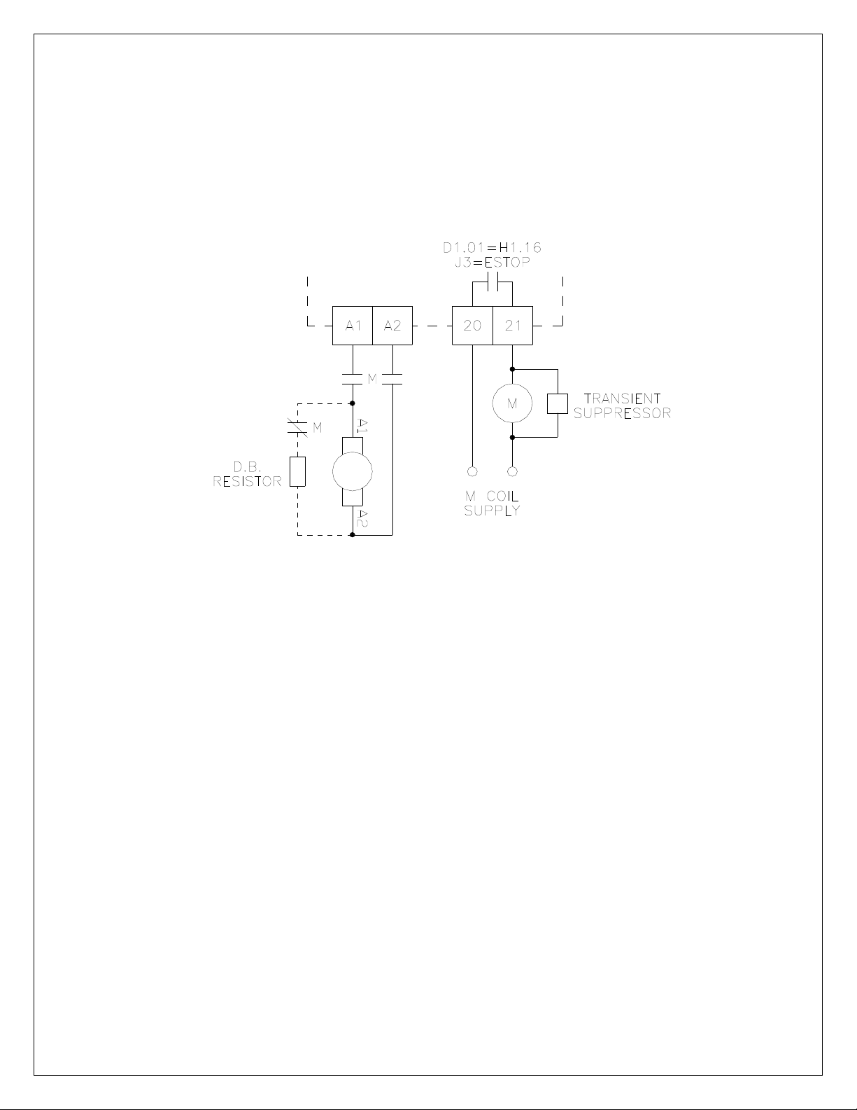
4.2 Motor Connections ............................................................................................................................. 8
4.3 Signal Connections .......................................................................................................................... 10
5. Human Machine Interface (HMI)..................................................................................................................... 12
5.1 Description of Interface .................................................................................................................... 12
6. Start Up Procedure ......................................................................................................................................... 15
6.1 Pretest.............................................................................................................................................. 15
6.2 Adjustment Procedure: Velocity (Speed) Regulator.........................................................................15
6.3 Adjustment Procedure: Torque (Current) Regulator........................................................................16
6.4 Calibration & Fine Tuning.................................................................................................................16
6.5 Password Protection ........................................................................................................................ 17
7. Programming & Adjustments .......................................................................................................................... 18
7.1 A: Options ........................................................................................................................................ 18
7.2 B: Digital Inputs ................................................................................................................................ 19
7.3 C: Analog Inputs............................................................................................................................... 24
7.4 D: Digital Outputs ............................................................................................................................. 27
7.5 E: Analog Outputs ............................................................................................................................ 29
7.6 F: Motor Data ................................................................................................................................... 31
7.7 G: Control Loops .............................................................................................................................. 33
7.8 H: Start/Stop Logic ........................................................................................................................... 38
7.9 I: Setpoints ....................................................................................................................................... 42
7.10 J: Ramps........................................................................................................................................ 44
7.11 K: Fault Logic ................................................................................................................................. 48
7.12 L: Applications................................................................................................................................ 53
7.13 M: Thresholds ................................................................................................................................ 63
7.14 N: Timers ....................................................................................................................................... 64
7.15 O: Logic Gates ............................................................................................................................... 66
7.16 P: Switches .................................................................................................................................... 69
7.17 Q: Internal Links ............................................................................................................................. 70
7.18 R: Communications........................................................................................................................ 71
7.19 S: Zero Speed ................................................................................................................................ 74
7.20 T: System ....................................................................................................................................... 75
7.21 U: Auxiliary ..................................................................................................................................... 77
7.22 Parameter Table ............................................................................................................................ 78
8. Troubleshooting .............................................................................................................................................. 90
9. Spare Parts ..................................................................................................................................................... 92
9.1 Printed Circuit Assemblies ............................................................................................................... 92
9.2 Fuses ............................................................................................................................................... 92
10. Prints ............................................................................................................................................................. 93
D14605 Control Board Assembly........................................................................................................... 93
D14602 Regulator Board Assembly....................................................................................................... 94
D14599 Power Board Assembly ............................................................................................................ 95
C14608 Keypad Board Assembly .......................................................................................................... 96
C14701 General Connections................................................................................................................ 97
D14702 Software Block Diagram ........................................................................................................... 98
11. Standard Terms & Conditions of Sale......................................................................................................... 103

3
List of Tables
Table 1: Model Rating Data...................................................................................................................................7
Table 2: HMI Description.....................................................................................................................................12
Table 3: Drive Monitor Descriptions ....................................................................................................................14
Table 4: Common Digital Input Functions ...........................................................................................................19
Table 5: Common Analog & Freq Input Functions ..............................................................................................24
Table 6: Analog Input Voltage Status Readings..................................................................................................25
Table 7: Analog Input 2 Current Status Readings...............................................................................................26
Table 8: Common Relay & Digital Output Functions...........................................................................................27
Table 9: Common Analog & Freq Output Functions ...........................................................................................29
Table 10: Analog Output Status ..........................................................................................................................30
Table 11: Drive Modes ........................................................................................................................................40
Table 12: Reference Select.................................................................................................................................42
Table 13: Faults 1................................................................................................................................................49
Table 14: Faults 2................................................................................................................................................49
Table 15: Alarms 1 ..............................................................................................................................................50
Table 16: Inertia Sensitivity .................................................................................................................................60
Table 17: Logic Gates Truth Table......................................................................................................................68
Table 18: Parameters..........................................................................................................................................78
Table 19: Faults...................................................................................................................................................90
Table 20: Recommended Line Fuses .................................................................................................................92
General Description
The TrooperPro Series is a microprocessor based D.C. motor control. The series provides control
of speed and torque control of 1/8HP-2HP D.C. motors. The controls are offered in chassis (-000)
and NEMA 4 enclosed (-E00) assemblies. Some standard features are listed below:
•Operates at 115/230VAC input for 90/180VDC motor armatures
•Same footprint/package as analog Trooperseries
•Armature voltage feedback, tachometer feedback, and encoder feedback
•Power On/Off switch (enclosed models only)
•9 button keypad with 2 line by 16 character display
•USB connectivity
•Compatible with Carotron's free CaroLink software
•Option port
1

4
Specifications
2.1 Electrical
A.C. Input Voltage Range
•
1 phase, 115-230VAC ± 10%, 50/60 Hz ± 2 Hz, 15A
Armature Output
•
0-90VDC @ 115VAC input
•
0-180VDC @ 230VAC input
Field Output
•
50/100VDC, 1A @ 115VAC input
•
100/200VDC, 1A @ 230VAC input
Horsepower Range
•
1/8-1HP @ 90VDC
•
1/4-2HP @ 180VDC
Power Supplies
•
+24 VDC (TB1-1): 50mA
•
+15 VDC (TB1-10): 50mA
•
+10 VDC (TB1-4): 50mA
Digital Inputs (Qty: 5)
•
Sink Mode
V
ih
=20.0 VDC max
V
il
=0.0 VDC min to 17.0 VDC max
•
Source Mode
V
ih
=8.0 VDC min to 30.0 VDC max
V
il
=5.0 VDC max
•
Current Consumption
5mA each (with 24V supply)
Analog Inputs (Qty: 2)
•
Voltage Mode
Max Input:±11 VDC
Input Impedance: 100KΩ
•
Current Mode (AI2 only)
Max Input: ±22 mADC
Input Impedance: 150Ω
•
Resolution: 12 bit
Tachometer Feedback/High Voltage Analog Input
•
Max Input: ±200 VDC
Encoder Feedback/Frequency Input
•
Frequency: 50kHz max, square wave
•
Uni-directional (single channel)
•
Single ended
•
Voltage: 15 VDC max
•
V
il
=0.0 VDC to 1.5 VDC max
•
V
ih
=2.5 VDC min to 15.0 VDC max
Relay Outputs (Qty: 2)
•
2 A @ 115 VAC (resistive)
•
2 A @ 60 VDC (resistive)
•
1 Form A, 1 Form C
Analog Outputs (Qty: 2)
•
±10 VDC max, 20mADC max
•
Resolution: 12 bit
Speed Regulation
•
Armature Feedback: ±0.5% of base speed
•
Tachometer Feedback: ±0.25% of base speed
•
Encoder Feedback: ±-0.25% of base speed
Torque Regulation
•
±1% of Range Selected
Speed Range
•
20:1 typical when using tachometer or encoder
feedback. May be less depending upon motor
characteristics
Temperature Range
•
Chassis: 0-55C
•
Enclosed: 0-40C
2

5
Figure 1: Chassis Models
Figure 2: Enclosed Models
2.2 Physical

6
Installation
3.1 Control Installation
TrooperPro motor controls require mounting in an upright position in an area that will permit
adequate airflow for cooling and ready access for making connections and for servicing. Because
cooler air is drawn in from the bottom and exhausted from the top, these areas should be kept clear
for about a six inch distance. Stacking of controls with one mounted above the other should be
minimized so that the upper control is not ventilated with hot exhaust air from the lower control.
Enclosures should be sized to provide adequate surface area for dissipating heat or provided with
forced ventilation with outside air from a duct system or enclosure fan. They should be mounted to a
cool surface not exposed to heat generated by nearby equipment.
Excess ambient temperatures within enclosures can reduce the life expectancy of electronic
components and can failure of the TrooperPro control. Contact Carotron for assistance in sizing
enclosures for particular horsepower ratings.
3.2 Wiring Guidelines
To prevent electrical interference and to minimize start-up problems, adhere to the following
guidelines.
Make no connections to ground other than the designated terminal strip location.
Use fully insulated and shielded cable for all signal wiring. The shield should be connected at one
end only to circuit common. The other end of the shield should be clipped and insulated to prevent
the possibility of accidental grounding.
Signal level wiring such as listed above should be routed separately from high level wiring such as
armature, field, and relay control wiring. When these two types of wire must cross, they should cross
at right angles to each other.
Any relays, contactors, starters, solenoids or electro-mechanical devices located in close proximity to
or on the same line supply as the motor control should have a transient suppression device such as
an MOV or R-C snubber connected in parallel with its coil (for AC coils). Diode suppression should
be used for DC coils. The suppressor should have short leads and should be connected as close to
the coil as possible.
3

7
Drive
Model
Motor
HP
AC Input
Voltage
Approx. Full Load
Line Amps
Recommended
Fuse (Amps)
Armature
Amps
Armature
Volts
1/8 2.3 3 1.5
1/4 4.3 5 3
1/2 7.9 8 6
3/4 11.7 15 8
1
115
15 15 10
90
1/4 2.3 3 1.5
1/2 4.3 5 3
1 7.9 8 6
1-1/2 12.2 15 8
TPR902-000
2
230
15 15 10
180
Table 1: Model Rating Data
Terminal Connections & Functions
4.1 AC Power Connections
Terminals L1 and L2 are the AC line inputs. Refer to Figure 3 below. Fusing is provided on board.
Refer to Table 1 above for recommended fuse sizing.
4
Figure 3: Power Connections

8
4.2 Motor Connections
Field
Many small motors are permanent magnet type or "PM" motors. These motors use magnets instead
of an electro-magnet winding. When using these motors, no connections are made to the F1 and F2
terminals.
A motor that has an electro-magnetic field winding will typically come in two types: single or dual
winding. A motor with a single field winding will be connected as shown in Figure 3. Most modern
motor fields consist of two windings that are connected in parallel for low voltage operation and in
series for high voltage operation. Refer to Figure 4. The winding leads are individually marked and
have a polarity that must be observed for proper and safe operation. Since direction of rotation is
controlled by field polarity as well as armature polarity, it is sometimes more convenient to swap the
smaller field leads when making corrections to the direction of rotation during initial installation. An
energized field should never be switched by relay, contactor, switch, or any other manual or electro-
mechanical device.
When the TrooperPro is supplied with 115VAC, the field is typically wired for low voltage operation
(i.e. 100VDC). When supplied with 230VAC, the motor field is typically wired for high voltage
operation (i.e. 200VDC). The F1 and F3 leads should always have the same polarity regardless of
the mode used.
Although rarely needed, a half-voltage field output can be obtained from the drive by connecting the
motor field windings across terminals L1 and F2 (instead of F1 and F2). Refer to Figure 5 below. In
these cases, an AC input of 115VAC will produce a field voltage of 50VDC. An input of 230VAC will
produce a field voltage of 100VDC.
Figure 4: Motor Field Connections
Figure 5: Half Wave Motor Field Connections

9
Armature
The armature leads are usually the highest current wires associated with the drive and warrant
special attention to sizing based on current rating as well as length of run. Extra care should be used
where terminations and splices are made. Refer to Table 1 for typical armature voltage and current
ratings. Refer to Figure 3 for example connections w/o an armature contactor. Refer to Figure 6 for
example connections using an optional external armature contactor. Motor stopping time is
determined by inertia and friction characteristics of the load. This time can be decreased by use of
an optional dynamic braking (D.B.) resistor.
Motor Thermostat
Most motors include "J" or "P" leads that connect to an internal normally closed thermostat. When
used, these leads are typically connected in series with the E-STOP or RUN signals. This allows a
motor over-temperature condition to shut down the control.
Figure 6: Armature Connections with Optional Contactor

10
4.3 Signal Connections
Figure 7 shows the typical signal connections to an Trooper® Pro drive. When operated, the
Emergency Stop contacts at terminal 3 will immediately clamp all control signals. If an armature
contactor is used (via Relay Output 1), it will also de-energize to disconnect the armature from the
bridge output.
Figure 7: Signal Connections

11
The TrooperPro supports three different start/stop logic schemes (four including the local mode).
Refer to Figure 8 below. The momentary scheme (often called 3 wire) uses momentary pushbuttons
to control the starting and stopping of the drive. A selector switch or a contact controls the direction.
The other two schemes use maintained contacts (often called 2 wire mode). In the Run/Direction
scheme, a single contact starts and stops the drive while another contact selects direction. In the
final scheme, each contact starts the drive and selects the direction. Parameter H1.01 needs to be
set appropriately.
The drive also has the capability to interface with either sinking or sourcing logic controls. Sourcing
(PNP) logic is selected by setting jumper J1 to the SRC position. This places an internal pull down
resistor on each input. The external switch or sensor must then drive the input high to activate the
input. Sinking (NPN) logic is selected by setting jumper J1 to the SNK position. This places an
internal pull up resistor on each input. The external switch or sensor must then sink (pull down) the
input to common to activate the input. Refer to Figure 9 below.
Figure 9: Sink/Source Wiring
Figure 8: Start Stop Logic

12
Human Machine Interface (HMI)
5.1 Description of Interface
The Human Machine Interface (HMI) is the primary method for accessing the drive's parameters. It
allows for custom user configuration, monitoring, and troubleshooting. As seen in Figure 10, the HMI
consists of a 2 line by 16 characters display, 9 button keypad, and 4 LEDs.
Figure 10: Keypad
Index Item Description
1 F1
Softkeys. The functionality of this key varies depending upon the
displayed menu. When utilized, text above the key displays its
function.
2 Start Key Places the drive in run mode when in local mode
3 Stop Key Stops the drive in all modes
4 Esc/Left Key •Returns to the previous menu
•Moves cursor one place to the left
5 Reset/Right Key •Clears drive fault (on a DM screen)
•Moves cursor one place to the right
6 Local/Remote Key Switches the drive between local and remote control
7 Enter Key •Used to accept/enter parameter values
•Moves cursor one place to the right
8 Up/Down Keys •Scrolls to the next menu display
•Increments/decrements cursor value
9 Run LED
On: Drive is in run mode and has reference
Flashing: Drive is in run mode with no reference
Off: Drive is not in run mode
10 Local LED On: Drive is in Local mode
Off: Drive is in Remote mode
11 Alarm LED On: An alarm is present
Off: No alarms present
12 Fault LED
On: A fault is present. Fault is not active and can be reset.
Flashing: Fault present and currently active. Cannot be reset.
Off: No faults present
Table 2: HMI Description
5
REF: 10.00%
MODE: RUN

13
When power is applied to the drive, the HMI displays the drive's firmware version. After a short
timeout, the Drive Monitor 1 (DM01) screen is displayed. Navigation through the menu is achieved
by using the Up, Down, Left, Right, Escape, and Enter keys.
Figure 11: Menu Structure

14
Monitors
The Monitors section contain the Drive Monitor screens. Each of theses screens displays various
drive status information.
Monitor Description
DM01 Reference/Mode
DM02 Reference/Act Speed
DM03 Local Direction
DM04 Local Jog
DM05 Armature Status
DM06 Fault Status
DM07 Alarm Status
DM08 Velocity Loop Status
DM09 Current Loop Status
DM10 Loop Outputs
DM11 Tachometer Status
DM12 Encoder Status
DM13 Drive Model/Firmware
Table 3: Drive Monitor Descriptions
Programming
The drive parameters are located under the Programming section. Each drive parameter has a
unique identifier tag that consists of an alpha group code, and numeric block code, and a two digit
numeric index. For example, parameter C2.04 is in Group C, Block 2, and Index 4. When the
programming section is first displayed, the first parameter (A1.01) is displayed with the Group Code
flashing (i.e. the 'A'). The Up/Down keys are then used to change the Group Code to the desired
value. Pressing the Reset/Right key will move the cursor to the right and cause the Block Code to
begin flashing. The Up/Down keys are then used to change the Block Code. Pressing the
Reset/Right key will move the cursor to the right and cause the Index Code to begin flashing. The
Up/Down keys are used to change the Index to display the desired parameter. Pressing Escape/Left
key will move the cursor left.
Once a parameter is displayed, pressing the Enter key will allow its value to be modified. The current
value of the parameter (or a digit in its value) will begin flashing. The Up/Down keys are used to
adjust the value. If the parameter is a numeric value, the Reset/Right key can be used to shift the
cursor to the right to allow other digits to be adjusted. Pressing the Reset/Right key when the cursor
is on the last digit will cause the cursor to be placed on the first digit. Once the desired value is
displayed, the value can be entered by pressing the Enter key. The Escape/Left key will move the
cursor to the left. Pressing this key when cursor is in the left most column will exit the parameter
adjustment screen without changing the parameter value.
Note: When parameters are altered via the keypad, the changes are saved automatically.
Modified Parameters
This section contains a list of parameters that have been modified from the default factory preset
value. The Up/Down keys are used to scroll through the list. Press the Enter key to edit the value.
Wizards
This section contains various drive related wizards that aid in drive setup.

15
Start Up Procedure
6.1 Pretest
1. Verify incoming power supply voltage. Input voltage should be checked ahead of the
supplying circuit breaker, disconnect switch, etc. before it is switched on.
2. Connections should be visually inspected and checked for tightness. An ohmmeter can
be used to check for ground faults. Ground faults in un-isolated circuits of the armature
and field can cause fuse blowing and damage to the motor and control. To check for
grounds with an ohmmeter, select a high resistance scale such as R x 100K ohms or
greater. Test from each connection terminal (including shields) to chassis ground and be
suspicious of any resistance reading less than 500K ohms.
3. Adjust external reference (Analog Input 1) at terminal 5 to 0 volts.
4. Apply power. On initial power up, the drive should display an Invalid Motor Data fault.
Press CLOSE to exit. When asked to run the Basic Setup Wizard, select YES. If the
wizard was cancelled, it can be re-started from the Wizards section in the menu.
6.2 Adjustment Procedure: Velocity (Speed) Regulator
1. Presets
Use the Basic Setup Wizard to set the required parameters. The wizard will step you
through various drive parameters. When a parameter is displayed, press the ENT key
to edit its value. There are a number of required parameters. The wizard will not
allow you to proceed until a valid value has been entered. It is recommended that the
drive initially be setup using armature feedback even if a tachometer or encoder will
be used. This allows the proper feedback signal to be verified before using it for
control.
2. Clear any Faults
When the wizard is completed, the drive will try to clear any faults that are present. If
a fault is still present (i.e. the Fault LED is on or flashing), navigate to the DM06
screen to display the current fault. Once the fault condition is removed, the fault can
be cleared by pressing the RESET key while on any DM screen.
3. Validate E-STOP
This step is only required when using an external E-STOP. If not used, a jumper may
be wired in place of the E-STOP switch or the function of Digital Input 1 may be
altered. When an E-STOP is activated, the status display on the DM01 screen should
display E-STOP. When the E-STOP is cleared, the status should display STOP or
FAULT. If the E-STOP status is not displayed correctly, check the wiring. Also ensure
jumper J2 is in the proper position. Refer to Figure 7. Do not proceed until the E-
STOP functions properly.
4. Safety Check
During the following steps the motor will be rotated. If excessive speed or wrong
direction of rotation could damage the load, it may be wise to de-couple the load until
proper control is verified.
5. Check Motor Rotation
While displaying the DM01 screen, place the drive in local mode by pressing the
LOCAL/REMOTE key. The Local LED should be on. Press the Up key until DM04 is
displayed. Press and hold the F1 key to jog the drive. The armature contactor should
close and the motor should rotate slowly. Observe the direction of rotation. Release
F1 to stop the drive. If the motor rotation is reversed, remove all power and reverse
the motor armature or field wires. After re-applying power, repeat this step to verify
motor direction.
6. Validate External Start/Stop
Press the LOCAL/REMOTE key to return the drive to Remote mode. The Local mode
6

16
LED should be off. Adjust the external reference signal connected to terminal 5 to its
minimum. Typically, the reference value on DM01 should be approximately zero.
Place the drive in Run mode via the external contacts. Slowly increase the external
reference until the motor is rotating. Issue a stop command using the external
contacts and verify the motor stops and the contactor de-energizes.
7. Validate Reverse Direction
This step is optional and only required if reverse direction is needed. With reference
at minimum, run the drive in the reverse direction. Slowly increase the reference and
verify motor runs in reverse direction. Stop drive.
8. Validate Tachometer Feedback (required only if a motor mounted tachometer is used)
Proper tachometer operation should be checked while the drive is running in Armature
Feedback. Place the drive in run mode and run at a low speed (approximately 20%).
On the display, navigate to DM11. Compare Armature feedback to Tachometer
feedback. The values should be approximately equal (within 5%). If the values have
approximately the same value but the wrong polarity, press the Stop button and invert
the tachometer feedback by setting parameter F2.02 to On. Place the drive back in
the run mode and re-check. If the values are not equal, verify the tachometer jumper
J2 is set properly. Once corrected and the values are equal at low speeds, increase
speed and check at higher speeds. If the values are approximately equal throughout
the speed range, the drive can be placed in tachometer feedback. With the drive in
the stop mode, set parameter G2.15 to Tachometer. Run drive and verify proper
operation.
9. Validate Encoder Feedback (required only if a motor mounted encoder is used)
Proper encoder operation should be checked while the drive is running in Armature
Feedback. Place the drive in run mode and run at a low speed (approximately 20%).
On the display, navigate to DM12. Compare Armature feedback to Encoder feedback.
The values should be approximately equal (within 5%). If the values have
approximately the same value but the wrong polarity, press the Stop button and invert
the encoder feedback by setting parameter F3.03 to On. Place the drive back in the
run mode and re-check. If the values are not equal, verify the encoder data is entered
properly in section F2 (or the wizard). Once corrected and the values are equal at low
speeds, increase speed and check at higher speeds. If the values are approximately
equal throughout the speed range, the drive can be placed in encoder feedback. With
the drive in the stop mode, set parameter G2.15 to Encoder. Run drive and verify
proper operation.
6.3 Adjustment Procedure: Torque (Current) Regulator
1. Presets
Set up the TrooperPro drive as a normal velocity regulator to run at the motor's
base speed using armature feedback. Refer to Section 6.2. Once correct operation in
this mode has been achieved, proceed with the following steps.
2. Parameters
Re-run the Basic Setup Wizard and set the Operating Mode to TORQUE. Continue
through the wizard and enter any required data.
3. Test
With reference at minimum, place drive in run mode. Navigate to DM05 to display the
armature current. Slowly increase reference and verify control of armature current.
6.4 Calibration & Fine Tuning
1. If the drive is using armature feedback (i.e. G2.15 is set to ARMATURE), then IR
Compensation (G2.09) can be adjusted to improve the speed regulation with load
changes. Adjustment is best done when the motor or machine can be loaded normally. If

17
the motor is normally operated at a particular speed, adjust IR Compensation (G2.09)
while running at that speed. If the motor operates under load over a wide speed range,
pick a speed near mid-range to make the adjustment. Adjust as follows:
Operate the unloaded motor at the normal or mid-range speed and note the exact
speed using a hand tachometer or other speed measuring device. While still
monitoring speed, apply normal load. The reduction in speed of a fully loaded motor
will usually fall between 2 and 13% of rated or "base" speed. Slowly increase IR
Compensation (G2.09) until the loaded speed equals the unloaded speed measured
in the previous step. Making this adjustment may now cause the unloaded speed to
be slightly higher. Repeat this procedure until there is no difference between loaded
and unloaded speed levels. Use care not to set the adjustment too high or speed
increase with load and instability may result. NOTE: For this adjustment, do not use
armature voltage feedback (AFB) to measure speed. Armature voltage is not an exact
indication of loaded motor speed!
2. The Current Proportional Gain (G1.16), Current Integral Time (G1.17), Velocity
Proportional Gain (G2.21), and Velocity Integral Time (G2.22) parameters are preset
by Carotron to provide stable and responsive performance under most load conditions.
When required, the drive performance can be optimized for a particular application or to
correct undesirable operation by use of these adjustments. The adjustments are complex
though and can adversely affect operation if not properly set. In general, the settings that
give the most stable operation do not always give the fastest response.
6.5 Password Protection
If password protection is required, set the appropriate password under A1.04. Please note
that this is a special hidden parameter. You must first display A1.03. Then press F1 key and
then the Up key to display A1.04. Once A1.04 has a value other than zero, parameters can
be viewed but cannot be changed. Changes can only be made by first entering the password
into parameter A1.05. Once all changes have been made, A1.05 can be manually returned
to 0 to logout. The drive also has a timeout feature, that automatically clears the entered
password in A1.05 after 5 minutes.

18
Programming & Adjustments
Programming and adjustment of the TrooperPro is
accomplished by changing parameter settings. Each parameter
has a Tag identifier and a descriptive name. Parameters are
separated into groups and blocks according to their function. The
following sections contain each software block diagram and
descriptions of each parameter function. Refer to Figure 12 for key
conventions that are used in the block diagrams. Each parameter
is one of three types: Read-Write (RW), Inhibit Change while
Running (ICR), or Read-Only (RO). ICR parameters can be
changed only when the drive is not running.
7.1 A: Options
These parameters set the drive's basic operating mode.
A1: Options
A1.02 Operating Mode (ICR, Preset: Velocity)
Sets the drive's operating mode.
VELOCITY
Drive regulates motor speed.
TORQUE
Drive regulates motor torque (or armature current).
A1.03 Initialize (ICR, Preset: 0)
9999: Re-initializes the drive and returns all parameters to the factory default setting.
Range: 0..65535
A1.04 Define Password (R/W, Preset: 0)
A numeric password may be set to prevent unauthorized parameter changes. After a numeric
password has been entered, the drive allows all parameters to be viewed, but prevents changes
from being made. Only after a valid password has been entered into A1.05 can changes be
made. This parameter requires a special keystroke to display. With A1.03 displayed, press F1
and then UP. Range: 0..65535
A1.05 Enter Password (R/W, Preset: 0)
If a numeric password has been defined in parameter A1.04, the same password must be
entered into parameter A1.05 before any parameter changes can be made. As a security
feature, the drive automatically clears the entered password after 5 minutes. Range: 0..65535
7
Figure 12
Figure 13

19
7.2 B: Digital Inputs
These parameters configure the drive's physical digital inputs (digital & frequency).
B1: Digital Input 1
B1.01 Digital Input 1 Destination (ICR, Preset: H1.12 [Ext Run Enable])
Determines the function of the digital input. Each digital input can control (or write to) any R/W
parameter in the drive. The destination parameter contains the tag of the parameter the input will
control (i.e. the target parameter). Refer to Table 4 for a list of commonly used functions.
Value Function
H1.02 Start-Run-Run Fwd*
H1.03 NA-/Stop-Run Rev*
H1.04 Jog-Jog-Jog Fwd*
H1.05 Rev-Rev-Jog Rev*
H1.08 /Coast Stop
H1.09 /Quick Stop
H1.10 /Dynamic Brake Stop
H1.12 Ext Run Enable (E-Stop)
I
1.01 Aux Reference Enable
I
1.02 Ref Select (MSB)
I
1.03 Ref Select (LSB)
J1.18 Ramp 1 Bypass
K1.14 External Fault
K1.15 Fault Reset
L1.01 PID Enable
L1.02 PID Reset
L6.01 MOP Increase
L6.02 MOP Decrease
L6.07 MOP Reset
Table 4: Common Digital Input Functions
*The actual function is determined by the H1.01 setting.
Figure 14

20
B1.02 Digital Input 1 Status [Terminal 3] (RO)
Displays the status of the digital input. A value of OFF indicates the digital input is off or not
activated. A value of ON indicates the digital input is on or active.
B1.03 Digital Input 1 Off Value (RW)
This is the value written to the target parameter when the digital input's status is OFF. The limits
and units of these parameters will change to match the limits and units of the target parameter.
B1.04 Digital Input 1 On Value (RW)
This is the value written to the target parameter when the digital input's status is ON. The limits
and units of these parameters will change to match the limits and units of the target parameter.
B2: Digital Input 2
Digital Input 2 is functionally equivalent to Digital Input 1. Refer to B1.XX
B2.01 Digital Input 2 Destination (ICR, Preset: H1.02 [Run])
B2.02 Digital Input 2 Status (RO)
B2.03 Digital Input 2 Off Value (RW)
B2.04 Digital Input 2 On Value (RW)
B3: Digital Input 3
Digital Input 3 is functionally equivalent to Digital Input 1. Refer to B1.XX
B3.01 Digital Input 3 Destination (ICR, Preset: H1.03 [/Stop])
B3.02 Digital Input 3 Status (RO)
B3.03 Digital Input 3 Off Value (RW)
B3.04 Digital Input 3 On Value (RW)
Figure 15
Figure 16
This manual suits for next models
2
Table of contents
Popular Industrial Equipment manuals by other brands

ABB
ABB HT601733 Operation manual

Rockwell Automation
Rockwell Automation Allen-Bradley CrossBoard 141C-NFD Series installation instructions

Sima
Sima STAR 16 user guide

Endura
Endura ADAptive Sill Assembly instructions

PI
PI L-417. 9211E0B Series user manual

HOWA MACHINERY
HOWA MACHINERY H013MC instruction manual