6
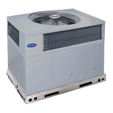
Vertical package air conditionners
Location designation
Before moving the unit, make sure that all panels are fastened in
place. Lift and lower with care. When choosing the location, in any
way the selected fashion, the following precautions have to be taken
into consideration:
- It is mandatory to comply with norm EN 378-3 on Safety and
Environmental Requirements. Part 3: “In situ” installation and
protection to people.
- It is necessary to check that the structure supports the unit’s weigh
(please see weighs in technical characteristics sheet).
- The area where the unit will be located must be perfectly accessible
for cleaning and maintenance operations. Leave enough space so
that air can circulate around the unit (please check minimum free
space for maintenance).
- Foresee appropriate bumping devices in all the installation so that
noise and vibration transmission is avoided.
For being a unit designed to operate indoor, with ducted discharge
and return, both in the internal circuit as in the external circuit, the
following aspects should be taken into account:
• All models can be installed on the floor or over a mount or steel
profile (in order to avoid the transmission of vibrations, it is
recommended to mount anti-vibratory supports).
• Important: In any case, check that the unit remains perfectly
levelled.
• Ifintheinternaland/or external circuit the air return is not ducted, it
isnecessaryto provide forgrillesofappropriate sizes intheplenum
formedbytheroof,forgedandwallsinorderthatthecircuitmakes
the aspiration of the return air.
7. LOCATION AND ASSEMBLING
Anchorage for antivibrators
A
B
Minimum free space for commissioning and
maintenance operations
E
D
A
B
C
Sound level
These units are designed to work with a low acoustic level. In any
case, the design of the installation the outer environment, the kind
of building for the noise transmitted in the air and the solid elements
for the vibration transmission must be taken into consideration for the
acoustic radiation.
If necessary, commission a study to an acoustic technician.
C) The sound pressure level of the unit, with the ducted return and
supply connections, measured at a distance of 5 metres, in open field,
directivity at 2 and 1.5 metres from the ground is:
B) The sound power level in the indoor fan outlet to be taken into
account for the silencer calculation:
A) The sound power level in the outdoor fan outlet to be taken into
account for the silencer calculation:
Note: The sound pressure level depends on the installation conditions
and, as such, is only indicated as a guide.
50NZ/NF A (mm) B (mm)
080 / 090 1.116 695
120 / 160 1.382 744
180 2.103 695
240 / 320 2.646 744
50NZ/NF A (mm) B (mm) C (mm) D (mm) E (mm)
080 1.000 600 900 600 1.500
090 1.200 600 900 600 1.500
120 1.100 750 900 750 1.500
160 1.100 750 900 750 1.500
180 1.200 600 900 600 1.500
240 1.200 750 900 750 2.000
320 1.500 750 900 750 2.000
50NZ/NF 080 090 120 160 180 240 320
dB(A) 74,4 76,3 81,9 83,6 79,3 84,9 86,6
50NZ/NF 080 090 120 160 180 240 320
dB(A) 79,4 75,1 77,5 80,2 77,8 83,1 79,0
50NZ/NF 080 090 120 160 180 240 320
dB(A) 65,7 67,9 71,4 74,0 70,8 75,2 76,0
Note: Diameter antivibration anchoring: 18 mm.
