2
Hardware 51.................................
Actuators 51................................
Supply Air Temperature Sensor 51..............
Outside Air Temperature Sensor 51.............
Enthalpy Control Sensor Configuration 51........
Operating Sequences 52........................
Staged Air Volume (3--Speed) Fan Motor 52......
W7220 Economizer Control 52.................
Base Unit Controls 52........................
Cooling, Unit With EconoMi$erRX
Without CO2Sensor 52.......................
Heating With EconoMi$er X 54.................
Demand Controlled Ventilation 55..............
Setup and Configuration 55.....................
Initial Menu Display 55.......................
Time--out and Screensaver 55..................
Checkout 55.................................
Status 56...................................
Calibration of Sensors 56......................
Resetting All Defaults 56......................
Troubleshooting 56............................
Power Up Delay 56..........................
Power Loss (Outage or Brownout) 56............
Alarms 56..................................
Clearing Alarms 56..........................
Control Set Point and Configuration Log 59........
Staged Air Volume (SAVt)
with Variable Frequency Drive 62..................
Multi--Speed VFD Display Kit
(Field--Installed Accessory) 63....................
Connecting the Keypad to the VFD 63.............
Program the VFD for 3 Discrete
Indoor Fan Speeds 64..........................
Smoke Detectors 80...........................
Return Air Sensor Tube Installation 80...........
Smoke Detector Test Magnet 80................
Additional Application Data 80.................
Step 13 -- Install Accessories 80...................
Step 14 -- Check Belt Tension 81...................
UNIT START--UP CHECKLIST 83..................
SAFETY CONSIDERATIONS
Improper installation, adjustment, alteration, service,
maintenance, or use can cause explosion, fire, electrical
shock or other conditions which may cause personal injury
or property damage. Consult a qualified installer, service
agency, or your distributor or branch for information or
assistance. The qualified installer or agency must use
factory--authorized kits or accessories when modifying this
product. Refer to the individual instructions packaged with
the kits or accessories when installing.
Follow all safety codes. Wear safety glasses and work
gloves. Use quenching cloths for brazing operations and
have a fire extinguisher available. Read these instructions
thoroughly and follow all warnings or cautions attached to
the unit. Consult local building codes and appropriate
national electrical codes (in USA, ANSI/NFPA 70,
National Electrical Code (NEC); in Canada, CSA C22.1)
for special requirements.
It is important to recognize safety information. This is the
safety--alert symbol . When you see this symbol on the
unit and in instructions or manuals, be alert to the
potential for personal injury.
Understand the signal words DANGER, WARNING,
CAUTION, and NOTE. These words are used with the
safety--alert symbol. DANGER identifies the most serious
hazards which will result in severe personal injury or
death. WARNING signifies hazards which could result in
personal injury or death. CAUTION is used to identify
unsafe practices, which may result in minor personal
injury or product and property damage. NOTE is used to
highlight suggestions which will result in enhanced
installation, reliability, or operation.
FIRE, EXPLOSION HAZARD
Failure to follow this warning could result in personal
injury or death.
Disconnect gas piping from unit when leak testing at
pressure greater than 0.5 psig (3450 Pa). Pressures
greater than 0.5 psig (3450 Pa) will cause gas valve
damage resulting in hazardous condition. If gas valve is
subjected to pressure greater than 0.5 psig (3450 Pa), it
must be replaced before use. When pressure testing
field--supplied gas piping at pressures of 0.5 psig
(3450 Pa) or less, a unit connected to such piping must
be isolated by closing the manual gas valve.
!WARNING
FIRE HAZARD
Failure to follow this warning could result in personal
injury, death, and/or property damage.
Inlet pressure tab set screw must be tightened and 1/8in.
NPT pipe plug must be installed to prevent gas leaks.
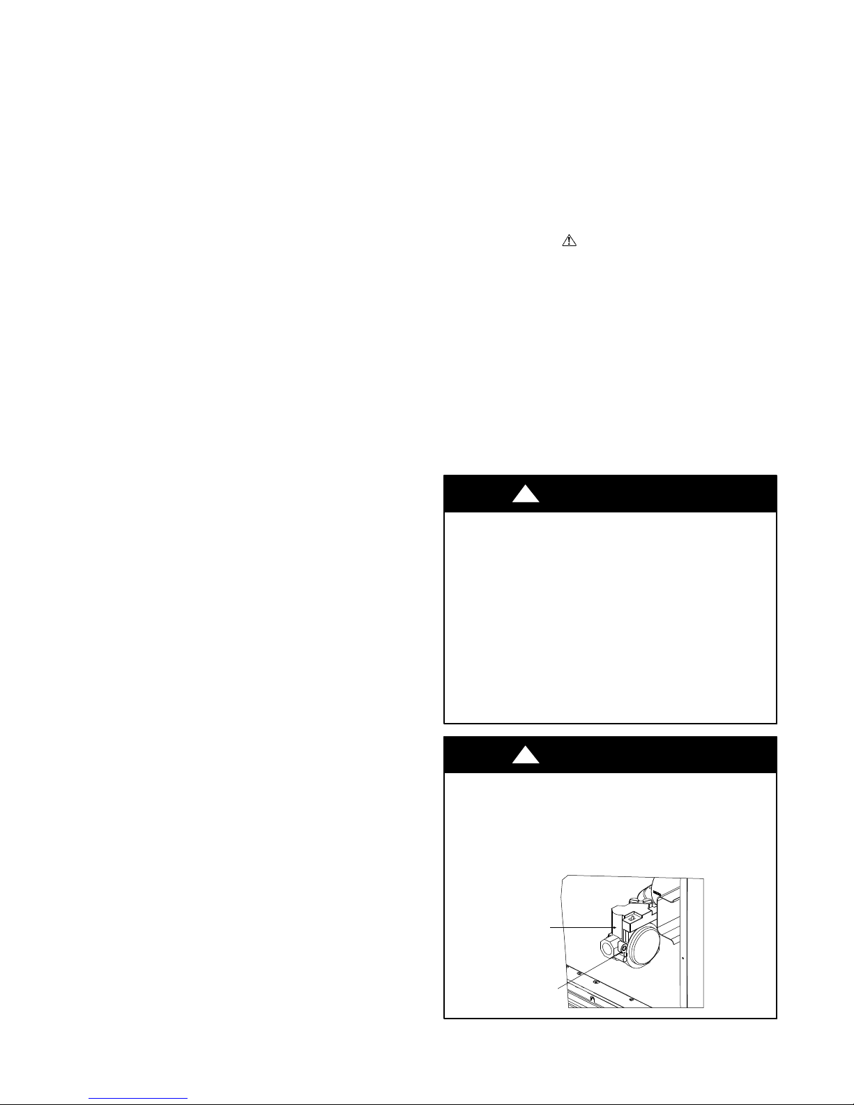
!WARNING
GAS VALVE
INLET PRESSURE
TAP SET SCREW
518


 null")


