1-3
1.4 DETAILED DESCRIPTION
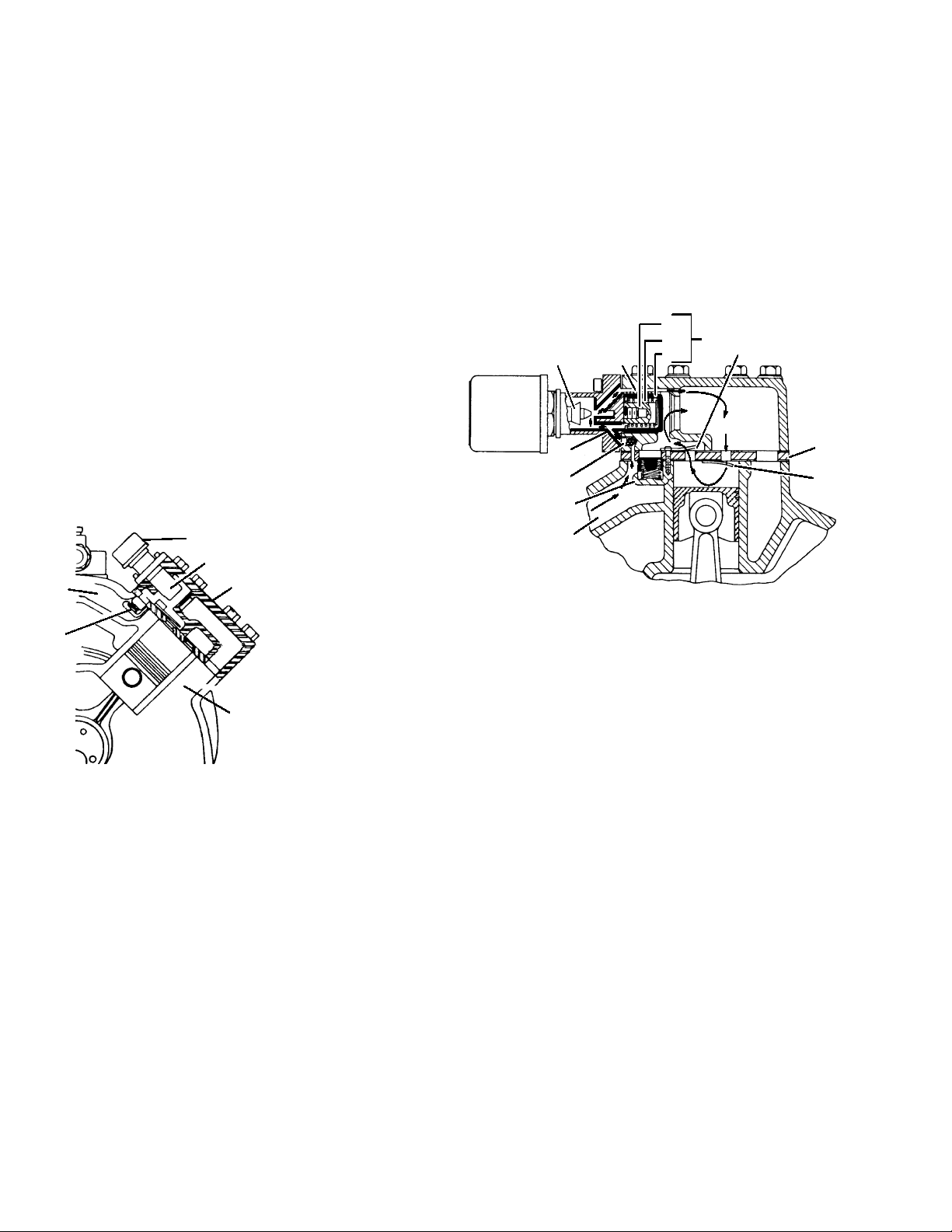
1.4.1 SUCTION AND DISCHARGE VALVES
The compressor uses reed type suction and discharge
valves made of highest quality steel for long life. The
valves operate against hardened integral seats in the
valve plate.
The downstroke of the piston admits refrigerant gas
through the suction valve, and then compresses this gas
on the upstroke, thereby raising it’s temperature and
pressure. The compressed gas is prevented from
re-entering the cylinder on it’s next downstroke by the
compressor discharge valve. (See Figure 1-2)
4512 3
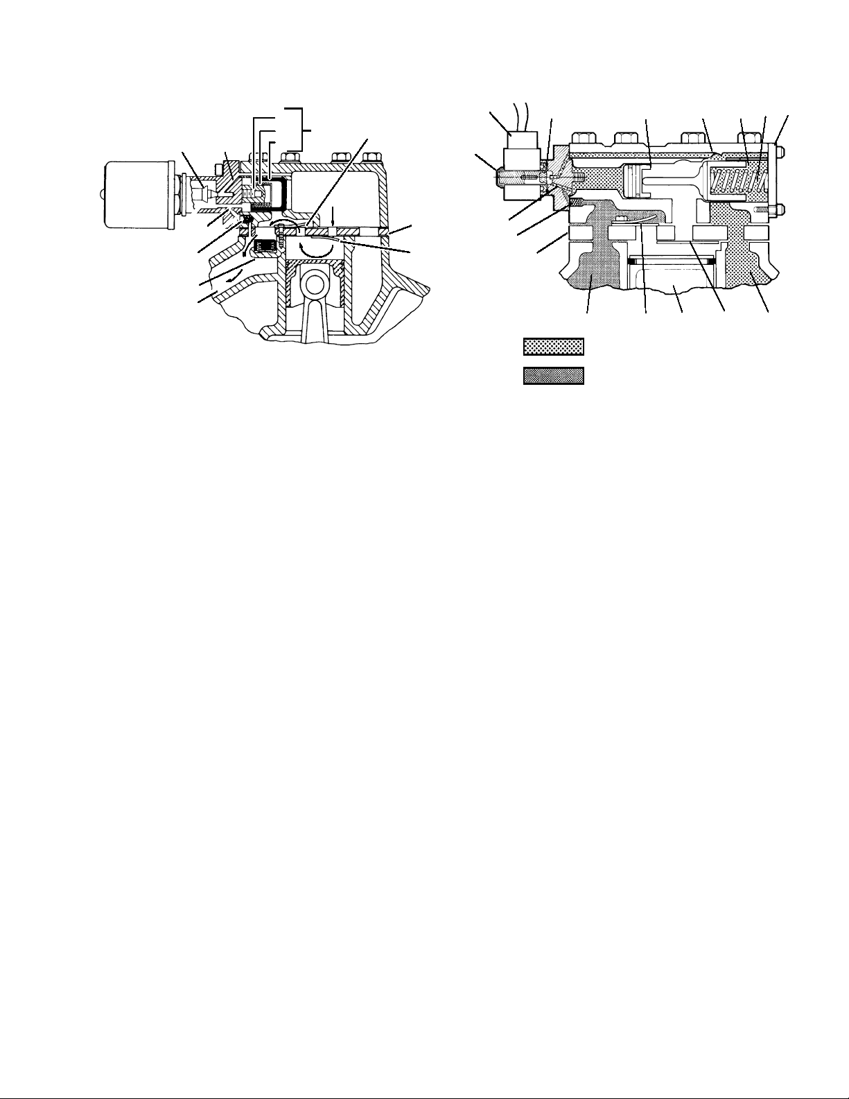
1. Position Spring
2. Suction Valve
3. Valve Plate
4. Discharge Valve
5. Discharge Valve Stop
Figure 1-2. Suction & Discharge Valve
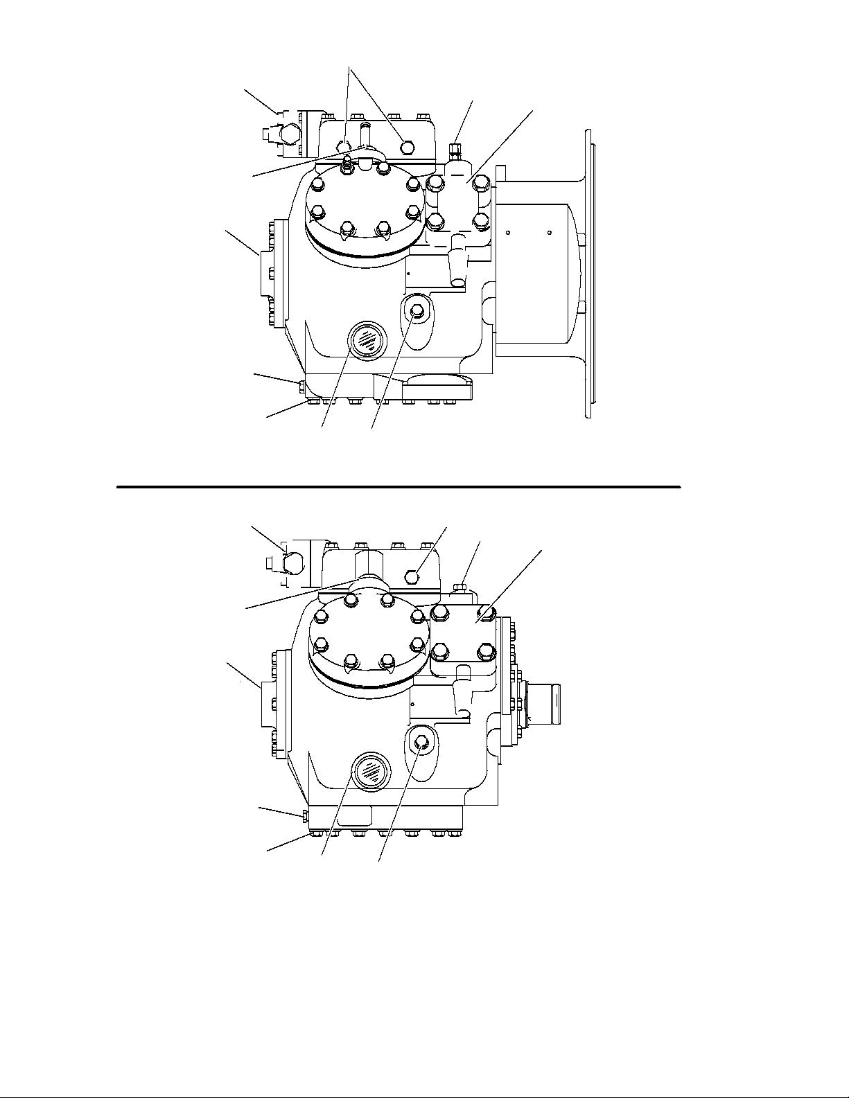
1.4.2 SUCTION & DISCHARGE SERVICE VALVES
The suction and discharge service valves used on the
compressor are equipped with mating flanges for
connection to flanges on the compressor. These valves
are provided with a double seat and a gauge connection,
which allows servicing of the compressor and refrigerant
lines (See Figure 1-1).
Turning the valve stem counterclockwise (all the way
out) will backseat the valve to open the suction or
discharge line to the compressor and close off the gauge
connection. In normal operation, the valve is backseated
to allow full flow through the valve. The valve should
always be backseated when connecting the service
manifold gauge lines to the gauge ports.
Turning the valve stem clockwise (all the way forward)
will frontseat the valve to close off the suction or discharge
line to isolate the compressor and open the gauge
connection.
To measure suction or discharge pressure, midseat
the valve by opening the valve clockwise about 2 turns.
With the valve stem midway between frontseated and
backseated positions, the suction or discharge line is
open to both the compressor and the gauge connection.
1.4.3 LUBRICATION SYSTEM
There are three types of oil pumps (Vane, Gear and
Low Profile Gear) driven directly from the end of the
compressor crankshaft (See Figure 1-3). Force-feed
lubrication of the compressor is accomplished by a oil pump
driven directly from the compressor crankshaft.
Refrigeration oil is drawn from the compressor crankcase
through the oil filter screen and pick up tube to the oil pump
located in the bearing head assembly. The crankshaft is
drilled to enable the pump to supply oil to the main
bearings, connecting rod bearings, and the shaft seal.
GEAR PUMPVANE PUMP
LOW PROFILE GEAR PUMP
Oil Pressure
Tap
Oil Pressure Tap
Figure 1-3. Oil Pumps
CAUTION
The Gear oil pump must be set to rotate in the
same direction as the crankshaft. (Refer to
section 3.4)
The oil flows to the pump end main bearings,
connecting rod bearings and seal end main bearings,
where the oil path is divided into two directions. The
largest quantity flows to the oil relief valve, which
regulates oil pressure at 15 to 18 psi (2.09 to 2.30 kg/cm@)
above suction pressure. When the oil pressure reaches 15
to 18 psi above suction pressure, the relief valve spring is
moved forward allowing oil to return to the crankcase.
The remaining oil flows through an orifice and into the
shaft seal cavity to provide shaft seal lubrication and
cooling. This oil is then returned to the crankcase
through an overflow passage.
An additional oil pressure relief valve, built into the
Gear and Low Profile Gear Oil Pump, is open at speeds
above 400 rpm to relieve a portion of the oil pressure to
the crankcase in order to maintain oil pressure below an
acceptable maximum. At low speeds, the valve is closed to
ensure adequate oil pressure at 400 rpm. At speeds above
1900 rpm, the oil pressure will be 25 to 30 psi (2.8 to 3.1
kg/cm@) above suction pressure.
The crankcase pressure equalization system consists of
two oil return check valves and a 1/8-inch pressure
equalization port between the suction manifold and
crankcase. Under normal conditions, check valves are open
and allow for oil return to the crankcase. Under flooded
start conditions, pressure rises in the crankcase and closes
the check valves, preventing excess oil loss. The
equalization port allows for release of excessive pressure,
that has built up in the crankcase, to the suction manifold;
thisensuresthattheoillossiskepttoaminimum.