manuals.online logo
Brands
  1. Home
  2. •
  3. Brands
  4. •
  5. Carrier
  6. •
  7. Controllers
  8. •
  9. Carrier Networker Wall Control User manual

Carrier Networker Wall Control User manual

The manufacturer reserves the right to discontinue or change specifications or designs at any time without notice and without incurring obligations.
Note: that a flashing fan symbol indicates that the fan within the air-
conditioner appliance is yet to switch ON.
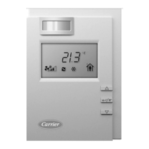
General Operating Symbols
•The thermometer on the display registers the current room
temperature with the small marker beside it indicating the
temperature that the heating/cooling system is currently set to
maintain.
•The bar adjacent to the Key 1 button is displayed when continuous
fan operation has been enabled using the Key 1 button.
•The Econ symbol is displayed when economy operation has been
enabled using the combination of the Function button immediately
followed by the Key 4 button
Note: that the actual room temperature appears in the top right of the
display screen.
Note: that “continuous” fan operation results in the fan being switched on
all the time to allow continuous circulation of air.
Note: that the economy operation is only available for reverse-cycle air-
conditioning systems.
Manual Operation
•Turn the Networker ON and press the Auto button until ‘Manual’
appears near the bottom left-hand corner of the screen. The Set
Temperature will now appear at the top of the screen with the current
room temperature still visible in the top right of the screen.
•The Set Temperature is the temperature the air-conditioning system
is set to maintain. To alter it use the Rotary Dial to select the
temperature required.
•Fan operation can be toggled between automatic and continuous
operation using the Key 1 button.
•Where applicable, economy operation can be toggled on and off
using the combination of the Function button followed by the Key 4
button.
Where applicable the mode of operation can be cycled between heat
only, cool only and heating/cooling operation using the Mode button.
Note: that the Networker limits the Set Temperature to a maximum of 30°C
and a minimum of 8°C. If the minimum is exceeded the air-conditioning
system is switched off and the Set Temperature indicated as ‘—‘.
Note: that the Networker remembers your last settings, and goes back to
them the next time you select manual operation.
Auto Program Operation
In Auto Program mode the Networker allows you to preset your air-
conditioner to switch ON or OFF when you wake, leave, return and just
before you sleep. Settings that can be defined include:
•The start time for the period.
•The set temperature to be maintained.
•Automatic or continuous fan operation.
•The Mode of operation (where applicable).
•Economy operation (where applicable).
In Auto Program mode the Networker has a pre-set Auto-Program for the
entire week the settings of which are defined in the table below.
Beginning Auto Program Operation
If the pre-set Auto-Program settings suit your lifestyle then all you need to
do is run the system in Auto Program mode by following these simple
steps:
•Use the On/Off button to turn the Networker ON.
•Use the Auto button until ‘Auto Program’ appears on the display
screen.
Temporarily Overriding the Auto-Program Settings
If these pre-set Auto-Program settings do not suit your lifestyle, you may
want to temporarily override them by simply using the Networker as you
would under manual operation, namely:
•To alter the Set Temperature use the Rotary Dial to select the
temperature required.
•To alter fan operation use the Key 1 button to toggle between
automatic and continuous operation.
•To alter the economy setting use the combination of the Function
button followed by the Key 4 button to toggle the economy operation
on and off (where applicable).
•To alter the operating mode use the Mode button to cycle between
heat only, cool only and heating/cooling operation (where applicable).
Period Description Temperature Fan Economy Mode
Wake Define the time and settings to operate your
system before you get up in the morning. 20°C AUTO OFF HEAT/COOL
Leave Define the time and settings to operate your
system when you have left for the day. -- (OFF) AUTO OFF HEAT/COOL
Return Define the time and settings to operate your
system just before you get home. 20°C AUTO OFF HEAT/COOL
Sleep Define the time and settings to operate your
system at night. -- (OFF) AUTO OFF HEAT/COOL
FIG 5
FIG 7
FIG 6
The manufacturer reserves the right to discontinue or change specifications or designs at any time without notice and without incurring obligations.
The word ‘Temporary’ will flash at the bottom of the display screen until the
current period ends.
The ‘Advance Period’ button (Key 2 button) has now become the ‘Cancel’
button. This button can be used to return the Networker to the settings
defined for the current time period
Note: that the Networker will revert to the settings defined for the next
period after the current period ends.
Advancing Time Period
If the settings defined by the current time period do not suit your lifestyle,
you may want to use the settings defined by the next time period. In this
case the ‘Advance Period’ button (Key 2 button) can be used to operate
the system using the settings defined by the next time period.
The word ‘Temporary’ will flash at the bottom of the display screen along
with the time period advanced to being displayed until the current time
period ends.
The ‘Advance Period’ button (Key 2 button) has now become the ‘Cancel’
button. This button can be used to return the Networker to the settings
defined for the current time period
Permanently Changing the Auto-Program Settings
If your lifestyle doesn’t match the pre-set Auto-Program you can change
the settings to your requirements by pressing the Prog button. After this is
done the words ‘Auto Program’ are flashed on the display screen to
indicate that the Auto-Program settings can be altered.
When changing the settings the Networker combines all the weekdays into
one block and both days of the weekend into another block, which are
listed on the left – hand side of the screen. To toggle the block that you
want to change the settings for press the Day button (Key 1 button).
To select the time period you want to change press the Period button (Key
2button) until the required time period is displayed.
The combination of the Function button followed by the Key 1 button
toggles the operation of the Key 1 button between selecting:
•The required block of days to program, and
•Automatic or continuous fan operation.
Note: that when selecting automatic or continuous fan operation ensure
that the word ‘Fan’ is next to the Key 1 button.
The ‘Time/Temp°’ button can be used to toggle the actual setting the
Rotary Dial alters, namely the time period Set Time or Set Temperature.
The setting that is flashing is the one that can be altered by the Rotary
Dial.
With the block of days and time period to program selected you can now
program the actual settings, namely:
•To alter the Set Time use the Rotary Dial to select the time required
when the Set Time is flashing.
•To alter the Set Temperature use the Rotary Dial to select the
temperature required when the Set Temperature is flashing.
•To alter fan operation use the Key 1 button to toggle between
automatic and continuous operation when the ‘Fan’ word is displayed.
•To alter the economy setting use the combination of the Function
button immediately followed by the Key 4 button to toggle the
economy operation on and off (where applicable).
•To alter the operating mode use the Mode button to cycle between
heat only, cool only and heating/cooling operation (where applicable).
•Once all settings have been defined save the new settings by
pressing the Prog button.
Note: that selecting a Set Temperature of (--) will turn the air-conditioner
OFF for that time period.
Operating the Fan Only
To simply circulate the air in the house, the fan can be made to run
continuously.
With the Networker switched OFF press the Fan button (Key 1 button).
After s small delay a small rotating fan symbol will appear and air should
begin circulating within the ductwork of your system.
To switch the fan OFF simply press the Fan button (Key 1 button).
Coded Messages
While the Networker is operating your system, it is also monitoring and
controlling every aspect of the system’s performance.
FIG 8
FIG 12
FIG 9
FIG 11
FIG 10
The manufacturer reserves the right to discontinue or change specifications or designs at any time without notice and without incurring obligations.
If anything unusual occurs, the Networker will display a message stating
“Air-Conditioner Fault – R01 Code#?? for assistance call 1300 652 349”
across the top of the screen. There are two parts to the message: the
R01 number designates which appliance has the fault, and the Code#??
relates to the type of fault. The screen will also display the spanner
symbol.
Note: Whenever such a message appears, it is a good idea to write it
down before doing anything else.
This code contains information that will enable Carrier to deal quickly
and easily with anything that requires their attention. With many of them
you will be asked to contact Carrier Service on 1300 652 349 and pass
on the message, the model and type of appliance.
Message repeating
Push the Function button followed by the Key 1 button quickly after to
repeat a message.
Resetting
If something has interrupted the unit’s operation, the word Reset could
appear beside the Key 4 button while a coded message is scrolling
across the top of the display.
When this is the case the Key 4 button can be used to re-start the unit.
If the unit does not resume normal operation or the error message re-
appears, contact Carrier Service.
Locking/Unlocking the Networker
To prevent any unwanted alterations being made to the operational
settings, the Networker can be locked via a 4-digit PIN number. In the
case of dual networkers, if one is locked the other is also locked.
There can be up to 3 PIN numbers stored into the controller, which
allows the Networker to be locked or unlocked by various users. If dual
networkers are installed, the user PIN numbers can only be set from the
Master Networker. The Slave Networker can only lock and unlock the
system and cannot access the PIN numbers.
Setting PIN Numbers
Push the Function button then the Key 2 button immediately after. The
screen will then display “Enter Your PIN number to lock the system”. Do
not enter numbers at this stage, please continue to the next step.
•Push the Mode button once. The screen will now display “User PIN
number reset – Enter master PIN number”. Do not enter numbers at
this stage, please continue to the next step.
•Push the Mode button once again. The screen will now display the
message “User PIN number 1 alteration – Enter current PIN”. If
this is the first time for setting the PIN numbers the current PIN will
be “1111”. If the PIN has been previously altered then enter your
current PIN.
•The screen will then display the message, “Enter the new PIN”.
•Enter your new 4-digit PIN number using a combination of Keys 1-5.
The screen will now display, “Repeat the entry of the new PIN”.
•Providing you re-enter the new PIN correctly the screen will now
display “Valid PIN – PIN altered”.
•Repeat this process to change the other PINs if necessary.
Remembering that all PINs are set as “1111” by default. Pushing the
Mode button, while you’re at the user PIN 1 alteration screen will give
access to set user PIN numbers 2 & 3.
•If an incorrect number is entered press the Auto button to clear all
digits, then re-enter your user PIN number.
•To exit this area at any time simply press the On/Off button.
Locking the Networker
•Push the Function button then the Key 2 button immediately after.
The screen will now display “Enter Your PIN number to lock the
system”.
•Enter your current user PIN number to lock the Networker. The
screen will now display “System locked out!”
 If an incorrect number is entered press the Auto button to clear all
digits, then re-enter your PIN number.
Unlocking the Networker
•Push the Function button then the Key 2 button immediately after.
The screen will now display “Enter Your PIN number to unlock the
system”.
•Enter your current user PIN number to unlock the Networker. The
screen will now display the message “System unlocked!”
•If an incorrect number is entered press the Auto button to clear all
digits, then re-enter your PIN number.
Note: If an invalid PIN is entered, the message “Invalid PIN entered – Try
again” will scroll across the screen. The user has three attempts at
entering a valid PIN number. On the third failed attempt the message
“Invalid PIN entered!” will be displayed. At this point the Networker will
abort the PIN entry screen, and resume the state that it was in prior to
attempting to enter the PIN. You can immediately retry entering the PIN
numbers, or if you cannot remember the PIN numbers, call Carrier Service
on 1300 652 349.
Dual Networker Operation (Where Applicable)
It is possible to have two networkers connected to the system. The two
networkers will operate together, one will be configured as a Master and
the other a Slave, and the settings for the system will be common on both
controllers.
The benefit of having two controllers is the convenience of making
adjustments to the settings as an adjustment made on one of the
networkers is immediately reflected on the other Networker. When locking
one of the networkers the other one will also be locked, and the system
can be unlocked at either Networker.
By default the Master Networker senses room temperature as is indicated
by the flashing heart symbol.
Note: that only the Master control has the ability to set the clock time, this
is one way of identifying which controller is the Master – Look for the word
‘clock’ beside the Key 5 button while the system is in the OFF position.
FIG 13
Other Carrier Controllers manuals

Carrier WTC-RCI-S User manual

Carrier

Carrier WTC-RCI-S User manual

Carrier CRDISKIT001A00 User manual

Carrier

Carrier CRDISKIT001A00 User manual

Carrier TruVu TV-MPCXP1628-NR Installation manual

Carrier

Carrier TruVu TV-MPCXP1628-NR Installation manual

Carrier 38CQ User manual

Carrier

Carrier 38CQ User manual

Carrier OPN-MTCC Instructions and recipes

Carrier

Carrier OPN-MTCC Instructions and recipes

Carrier 38CQ User manual

Carrier

Carrier 38CQ User manual

Carrier XCT7 40VCW117FQEE Installation instructions

Carrier

Carrier XCT7 40VCW117FQEE Installation instructions

Carrier VVT Bypass Installation manual

Carrier

Carrier VVT Bypass Installation manual

Carrier TruVu UC253-V Installation manual

Carrier

Carrier TruVu UC253-V Installation manual

Carrier 37HS Series User manual

Carrier

Carrier 37HS Series User manual

Carrier TruVu VVTZC-E2 Installation manual

Carrier

Carrier TruVu VVTZC-E2 Installation manual

Carrier 40BNC User manual

Carrier

Carrier 40BNC User manual

Carrier TruVu UCXP683T Installation manual

Carrier

Carrier TruVu UCXP683T Installation manual

Carrier SYSTEM PILOT 33PILOT-01 User manual

Carrier

Carrier SYSTEM PILOT 33PILOT-01 User manual

Carrier 40VMD 006 User manual

Carrier

Carrier 40VMD 006 User manual

Carrier 50CO Series Manual

Carrier

Carrier 50CO Series Manual

Carrier 40KMC User manual

Carrier

Carrier 40KMC User manual

Carrier WTC-B-207 User manual

Carrier

Carrier WTC-B-207 User manual

Carrier 42EL Aqualia Manual

Carrier

Carrier 42EL Aqualia Manual

Carrier 33ZCVAVTRM User manual

Carrier

Carrier 33ZCVAVTRM User manual

Carrier 38AKS User manual

Carrier

Carrier 38AKS User manual

Carrier RTU - OPEN User guide

Carrier

Carrier RTU - OPEN User guide

Carrier A Series User manual

Carrier

Carrier A Series User manual

Carrier VVT Bypass Installation manual

Carrier

Carrier VVT Bypass Installation manual

Popular Controllers manuals by other brands

AVer CL01 user manual

AVer

AVer CL01 user manual

Bray 98 Series Installation, operation and maintenance manual

Bray

Bray 98 Series Installation, operation and maintenance manual

Valcom V-VCU manual

Valcom

Valcom V-VCU manual

WESTECH SeaStar SS1024 instruction manual

WESTECH

WESTECH SeaStar SS1024 instruction manual

NOVAK GTB 2 - BASIC SET-UP Setup guide

NOVAK

NOVAK GTB 2 - BASIC SET-UP Setup guide

Watlow F4P Series user manual

Watlow

Watlow F4P Series user manual

weintek MT-508SV4 installation instructions

weintek

weintek MT-508SV4 installation instructions

Nico Technology 3010PL user manual

Nico Technology

Nico Technology 3010PL user manual

ALPHI TECHNOLOGY PCI-ISC8 Reference manual

ALPHI TECHNOLOGY

ALPHI TECHNOLOGY PCI-ISC8 Reference manual

Danfoss MCX08M user manual

Danfoss

Danfoss MCX08M user manual

Eurotronic CZW-250 operating instructions

Eurotronic

Eurotronic CZW-250 operating instructions

Festo SEC-ST-48-6-P01 Description

Festo

Festo SEC-ST-48-6-P01 Description

Lumiax MT2010 Connection manual

Lumiax

Lumiax MT2010 Connection manual

nuLEDs SpectraDrive16 Operation manual

nuLEDs

nuLEDs SpectraDrive16 Operation manual

Furrion FSCC40PW2 instruction manual

Furrion

Furrion FSCC40PW2 instruction manual

Eaton CGLine+ Quick installation manual

Eaton

Eaton CGLine+ Quick installation manual

Warm4Less MULTI-CLICK instruction manual

Warm4Less

Warm4Less MULTI-CLICK instruction manual

Gicam WIN6 manual

Gicam

Gicam WIN6 manual

manuals.online logo
manuals.online logoBrands
  • About & Mission
  • Contact us
  • Privacy Policy
  • Terms and Conditions

Copyright 2025 Manuals.Online. All Rights Reserved.