Wat l ow Ser i es F4P Oper at i ng f r om t he Fr ont Panel ■2.3
Gui ded Progr a mmi ng
The Series F4P software guides users through most
tasks. To accomplish a task, simply proceed through the
sequence of parameters. For each parameter, choose the
appropriate option or establish the value, then press the
Right key to proceed to the parameter on the next
screen. The task is complete when you return to the ini-
tial menu.
1. Use >or <to move the cursor to select an item
in a list.
2. Press the Right key ...
3. Enter the value and make a choice.
4. Press .again.
5. Repeat until you return to the original list.
To cha n ge a specific, sin gle para m et er, pr oceed throu gh
the parameter sequence without changing values until
you reach that parameter, then make your change. After
cha n gin g th e valu e, you ma y ba ck ou t of th e sequ en ce by
pressing the Left key or continue on through the
sequence by pressing the Right key. When you exit the
page, you must choose to Save Changes or Restore
Values.
.
.
.
Choose Cycle Time:__
>Variable Burst
Fixed Time
Choose Function:____
>Heat
Cool
Choose to Setup:____
>Control Output 1A
Control Output 2A
Main Page___________
Go to Operations
>Go to Setup
Go to Factory
Cust om Mai n Page
The Main Page shows error messages; input and output
status; and allows access to controller software. You can
cust om ize the Main P a ge t o display chosen in for m a t ion
by going to the Setup Page, Custom Main Page Menu.
(See Ch a pt er 4, Set u p P a ge, for inst r u ct ion s.)
Aut o a nd Manua l Ope rati on
The Series F4P controller can function as a static set
point cont r oller (a u t o m ode); or t h e u ser ca n dir ect ly
cont r ol t h e ou t pu t s (m a n u a l m ode).
In the static set point mode, the Series F4P can only be
oper a t ed in a closed-loop con figu r a t ion.
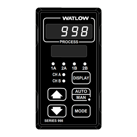
The Auto/Manual Indicator Light is on when the con-
troller is in manual mode. To toggle between manual and
auto mode, first press the Auto/Manual key å, then con-
fir m you r select ion in the lower displa y. Th e indicator
light will flash after you press åuntil you confirm your
choice or 10 secon ds h a ve ela psed. Wh ile in ma n u a l mode
you can adjust the output power level for process outputs
or tu r n r ela y or open collector ou t pu t s on or off.
çWARNING: Only auth or ized a n d qu a lified person n el
should change the set point on the controller. Failure to
comply wit h t h ese recommenda t ion s ma y resu lt in da m -
age to equipment and property and injury to personnel.
Static Set Point Control
When the Series F4P is in static set point mode:
•The Upper Display shows the actual process temper-
ature of input 1.
•The Lower Display shows the default or user-config-
ured Main Page.
To oper a t e t h e Series F4P a s a static set poin t cont r oller,
select SP1 in the Main Page then use the Up and Down
keys to adjust the set point.
Limits may be placed on the set point in the Set Point
Low Limit and Set Point High Limit parameters (Setup
Page > Analog Input 1).
✔Note:All con t r ol a ct ivit y st ops wh en you en t er th e
Setup Page, Analog Input, Digital Input, Control Output,
Ala r m Ou t pu t a n d Ret r a n sm it m en us.
✔Note: See also differential set point and ratio set
point.
