manuals.online logo
Brands
  1. Home
  2. •
  3. Brands
  4. •
  5. Carrier
  6. •
  7. Heat Pump
  8. •
  9. Carrier COMFORT 50EZ-A User manual

Carrier COMFORT 50EZ-A User manual

Installation Instructions
to the expe_
NOTE: Read the entire instruction manual before starting the
installation.
NOTE: Installer: Make sure the Owner's Manual and Service
Instructions are left with the unit after installation.
TABLE OF CONTENTS
PAGE
SAFETY CONSIDERATIONS ....................... 1-2
INTRODUCTION ................................... 2
RECEIVING AND INSTALLATION .................. 2-9
Check Equipment .................................. 2
Identify Unit .................................... 2
Inspect Shipment ................................. 2
Provide Unit Support ............................... 2
Roof Curb ...................................... 2
Slab Mount ..................................... 2
Provide Clearances ................................. 2
Rig and Place Unit ................................. 3
Inspection ...................................... 3
Rigging/Lifting of Unit ............................ 7
Select and Install Ductwork ........................... 7
Converting Horizontal Discharge Units to Downflow
(Vertical) Discharge Units .......................... 8
Provide for Condensate Disposal ...................... 9
Install Electrical Connections ......................... 9
High-Voltage Connections ......................... 9
Special Procedures for 208-V Operation .............. 10
Control Voltage Connections ....................... 10
Standard Connections ............................ 10
Transformer Protection ........................... 10
Accessory Electric heaters Installation ................ 10
PRE-START-UP ................................... 18
START-UP ..................................... 18-24
Checking Cooling & Heating Control Operation ........ 18
Check for Refrigerant Leaks ......................... 18
Start-Up Adjustments ............................. 18
50EZ-A Sequence of Operation .................... 19
Checking & Adjusting Refrigerant Charge ............ 19
Indoor Airflow & Airflow Adjustments .............. 19
Continuous Fan Operation ........................ 20
Defrost Control ................................... 24
Quiet Shift ..................................... 24
Defrost ....................................... 24
MAINTENANCE .................................. 24-
Air Filter ........................................ 24
Indoor Blower and Motor ........................... 24
Outdoor Coil, Indoor Coil, & Condensate Drain Pan ...... 25
Outdoor Fan ..................................... 25
Electrical Controls and Wiring ....................... 27
Refrigerant Circuit ................................. 27
Indoor Airflow ................................... 28
Metering Devices- TXV & Piston .................... 28
Pressure Switches ................................. 28
Loss of Charge Switch ............................. 28
High Pressure Switch .............................. 28
Copeland Scroll compressor (Puron Refrigerant) ......... 28
A09034
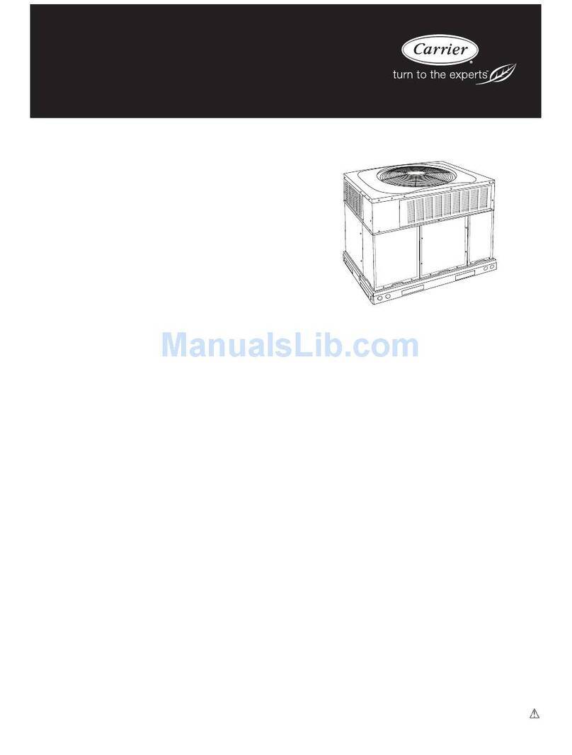
Fig. 1 - Unit 50EZ-A
Refrigerant System ................................ 28
Refrigerant .................................... 28
Compressor Oil ................................. 28
Servicing Systems on Roofs with Synthetic Materials .... 28
Liquid Line Filter Drier ........................... 29
Puron® (R-410A) Refrigerant Charging ............. 29
System Information ................................ 29
Loss of Charge Switch ............................ 29
Check Defrost Thermostat ......................... 29
TROUBLESHOOTING .............................. 29
START-UP CHECKLIST ............................ 29
SAFETY CONSIDERATIONS
Installation and servicing of this equipment can be hazardous due
to mechanical and electrical components. Only trained and
qualified personnel should install, repair, or service this equipment.
Untrained personnel can perform basic maintenance functions such
as cleaning and replacing air filters. All other operations must be
performed by trained service personnel. When working on this
equipment, observe precautions in the literature, on tags, and on
labels attached to or shipped with the unit and other safety
precautions that may apply.
Follow all safety codes. Wear safety glasses, protective clothing,
and work gloves. Use quenching cloth for brazing operations.
Have a fire extinguisher available. Read these instructions
thoroughly and follow all warnings or cautions included in
literature and attached to the unit. Consult local building codes, the
current editions of the National Electrical Code (NEC) NFPA 70.
In Canada refer to the current editions of the Canadian electrical
Code CSA C22.1.
Recognize safety information. This is the safety-alert symbol Z_.
When you see this symbol on the unit and in instructions or manu-
als, be alert to the potential for personal iniury. Understand these
signal words: DANGER, WARNING, and CAUTION. These
words are used with the safety-alert symbol. DANGER identifies
the most serious hazards which will result in severe personal iniury
ordeath.WARNINGsignifieshazardswhichcould result in per-
sonal injury or death. CAUTION is used to identify unsafe practic-
es which may result in minor personal injury or product and prop-
erty damage. NOTE is used to highlight suggestions which will
result in enhanced installation, reliability, or operation.
ELECTRICALSHOCK HAZARD
Failure to follow this warning could result in personal
injury or death.
Before installing or servicing system, always turn off main
power to system and install lockout tag. There may be
more than one disconnect switch. Turn off accessory heater
power switch if applicable.
FIRE, EXPLOSION, ELECTRICAL SHOCK
HAZARD
Failure to follow this warning could result in personal
injury, death or property damage.
A qualified installer or agency must use only
factory-authorized kits or accessories when modifying this
product.
CUT HAZARD
Failure to follow this caution may result in personal injury.
When removing access panels (see Fig. 20) or performing
maintenance functions inside your unit, be aware of sharp
sheet metal parts and screws. Although special care is taken
to reduce sharp edges to a minimum, be extremely careful
when handling parts or reaching into the unit.
INTRODUCTION
The 50EZ-A heat pump is fully self-contained and designed for
outdoor installation. (See Fig. 1.) Standard units are shipped in a
horizontal-discharge configuration for installation on a
groundlevel slab. Standard units can be converted to downflow
(vertical) discharge configurations for rooftop applications.
RECEIVING AND INSTALLATION
Step 1-- Check Equipment
Identify Unit
The unit model number and serial number are stamped on the unit
identification plate. Check this information against shipping
papers.
Inspect Shipment
Inspect for shipping damage before removing packaging materials.
If unit appears to be damaged or is torn loose from its anchorage,
have it examined by transportation inspectors before removal.
Forward claim papers directly to transportation company.
Manufacturer is not responsible for any damage incurred in transit.
Check all items against shipping list. Immediately notify the
nearest equipment distributor if any item is missing. To prevent
loss or damage, leave all parts in original packages until
installation.
If the unit is to be mounted on a curb in a downflow application,
review Step 5to determine which method is to be used to remove
the downflow panels before rigging and lifting into place. The
panel removal process may require the unit to be on the ground.
IMPORTANT: The unit must be secured to the curb by installing
screws through the bottom of the curb flange and into the unit base
rails. When installing large base units onto the common curb, the
screws must be installed before allowing the full weight of the unit
to rest on the curb. A minimum of six screws are required for large
base units. Failure to secure unit properly could result in an
unstable unit. See Warning near Rigging/Lifting information and
accessory curb instructions for more details.
Step 2 -- Provide Unit Support
Roof Curb
Install accessory roof curb in accordance with instructions shipped
with curb (See Fig. 4). Install insulation, cant strips, roofing, and
flashing. Ductwork must be attached to curb.
IMPORTANT: The gasketing of the unit to the roof curb is critical
for a watertight seal. Install gasketing material supplied with the
roof curb. Improperly applied gasketing also can result in air leaks
and poor unit performance.
Curb should be level to within 1/4 in. (6 mm) (See Fig. 6). This is
necessary for unit drain to function properly. Refer to accessory
roof curb installation instructions for additional information as
required.
Installation on older "G" series roof curbs.
Two accessory kits are available to aid in installing a new "G"
series unit on an old "G" roof curb.
1. Accessory kit number CPADCURB001A00, (small chassis)
and accessory kit number CPADCURB002A00, (large
chassis) includes roof curb adapter and gaskets for the
perimeter seal and duct openings. No additional
modifications to the curb are required when using this kit.
2. An alternative to the adapter curb is to modify the existing
curb by removing the outer horizontal flange and use
accessory kit number CPGSKTKIT001A00 which includes
spacer blocks (for easy alignment to existing curb) and
gaskets for the perimeter seal and duct openings. This kit is
used when existing curb is modified by removing outer
horizontal flange.
UNIT/STRUCTURAL DAMAGE HAZARD
Failure to follow this caution may result in personal injury.
Ensure there is sufficient clearance for saw blade when
cutting the outer horizontal flange of the roof curb so there
is no damage to the roof or flashing.
Slab Mount
Place the unit on a solid, level concrete pad that is a minimum of 4
in. (102 mm) thick with 2 in. (51 mm) above grade (See Fig. 8).
The slab should extend approximately 2 in. (51 mm) beyond the
casing on all 4 sides of the unit. Do not secure the unit to the slab
except when required by local codes.
Step 3-- Provide Clearances
The required minimum service clearances are shown in Fig. 2 and
3. Adequate ventilation and outdoor air must be provided. The
outdoor fan draws air through the outdoor coil and discharges it
through the top fan grille. Be sure that the fan discharge does not
recirculate to the outdoor coil. Do not locate the unit in either a
corner or under an overhead obstruction. The minimum clearance
under a partial overhang (such as a normal house overhang) is 48
in. (1219 mm)above the unit top. The maximum horizontal
extension of a partial overhang must not exceed 48 in. (1219 mm).
IMPORTANT: Do not restrict outdoor airflow. An air restriction
at either the outdoor-air inlet or the fan discharge may be
detrimental to compressor life.
Do not place the unit where water, ice, or snow from an overhang
or roof will damage or flood the unit. Do not install the unit on
carpeting or other combustible materials. Slab-mounted units
should be at least 4 in. (102 ram) above the highest expected water
and runoff levels. Do not use unit if it has been under water.
Step 4 -- Rig and Place Unit
Rigging and handling of this equipment can be hazardous for many
reasons due to the installation location (roofs, elevated structures,
etc.).
Only trained, qualified crane operators and ground support staff
should handle and install this equipment.
When working with this equipment, observe precautions in the
literature, on tags, stickers, and labels attached to the equipment, and
any other safety precautions that might apply.
Training for operators of the lifting equipment should include, but not
be limited to, the following:
1. Application of the lifter to the load, and adjustment of the lifts
to adapt to various sizes or kinds of loads.
2. Instruction in any special operation or precaution.
3. Condition of the load as it relates to operation of the lifting kit,
such as balance, temperature, etc.
Follow all applicable safety codes. Wear safety shoes and work
gloves.
INSPECTION
Prior to initial use, and at monthly intervals, all rigging shackles,
clevis pins, and straps should be visually inspected for any damage,
evidence of wear, structural deformation, or cracks. Particular
attention should be paid to excessive wear at hoist hooking points and
load support areas. Materials showing any kind of wear in these areas
nmst not be used and should be discarded.
UNIT FALLING HAZARD
Failure to follow this warning could result in personal iniury
or death.
Never stand beneath rigged units or lift over people.
PROPERTY DAMAGE HAZARD
Failure to follow this warning could result in personal
injury/death or property damage.
When straps are taut, the clevis should be a nfinimum of 36 in.
(914 ram) above the unit top cover.
I
I>a
L,
_°
[325 4]
32 58
[8_8 i _ ]
DR_I_4 OUTLET_
'3 70[190]_NT
X 0 88[R20]OEE_ _ LEFT SIDEVIEW
[]
3 HI8
[02_]
YO IPRESSO _
[]
!
// t
IIDNOR OOIL--' TOP VIEW "--IdT }OOl {:OIL
/
FRONTVIEW
UNIT
50EZ A24 30
50EZ A_O [5/5)0
_OEZ _36 {3/5)0
_OEZ _5_ 60
ELECTRICAL UNIT WT UNIT HEIGHT INMI4 CEI_TER OF GRAVIT_ INM_
CHARACTERISTICS LB K6 "_" X ,'
2135'230 .... 320145 o4218 1070 i934513i71434374716
-4
208230 I, 208230 S 60 352 'SO i4218 i070 ]'7193454 _01501i';'114i_a'I_45t43i4;5_472/61816
208250 i 208230 5 60 336 1523 42 18 !0_0 19 SOi_ 4 _4
46056,3 55,31_8642 l 8 10}'n
CORNER_&'E]SHTLBMG
UIqITS _OLTAGE IIiii
30EZ A24 3O 2,38¸¸¸¸230640 29
50E_ _G _3_ _ _/230
_(OTE ALL TA8LE DST_ HELEiAIqT FOR ALL F&ETOR_ INSTALLE[}
OPTIOUS EXCEPT EGO_40NIZER REQUIR_ CLEARANCESTO COI_BUSTIBLEMATL. IsCHES [Nb]
TO? OF UNIT............................... _ [305 6]
OUCT SIDE OF UNIT 2 [50 8]
S[OE ORPOS[TE DUCTS .......................... 14 [355 6]
BOTTOI_OF UNIT ................. 0 [00]
ELEI;TRIE-'LPANEL 36 [9i4 4]
NEE. REQUIRED CLEARANCES• I 4CHES [r_4]
BET_'EEI' U ITS PO_'ER EsTRY SlOE 12 [i066 8]
UNIT A[i [4GiOLN E') SURF_ ES PO',_ER ENTR' SIEE ..... 36 [914 O]
d_IT AI40 BLOCK OR 0% ETE WALLS AND OTHER
_,I<OUs)E) L FAES P,X%E Er, TRT I[E 4;' [106 8]
REQUIRB_) CLEARANCE FOR OPERATION AND SER'_IClN6 I'_OH ES [M_4]
E_'d _ OIL AC ESS SI E ........ 56 [ 40]
/',}WE EtqTR SI}E 42 [/0668]
,EXCEPT FOR HEO [EOUIIE_!EHTS)
IIIT TOP ,18 [1 19 ]
SIDE OPPOSITE DOTS .......................... 56 [9 40]
OUCT PA4EL IR [_04 6]_
_SqlHII4[4 OIST'_4EE$ IF NIT IS PLACER LESS THA_ 12 [30, 8] FR,314W&LL
SYSTEM,THEN STHTEN PERFiSR_HCE I,_YBE EO_IPROMIHE[}
_i?'_
[i o
_ o¸¸¸¸16 _ic _i T [ [
[66 i _t>O b - O©
sI
[g ]
[2'508] [5405] [258]
DIIE4SI(isS IN [] ARE 14 N_
RIGHTSIDEVIEW REAR VIEW
>
g
$
I
bq
&
=
3/4" [/9 i]8RAI_' h P T0 TLET // _ 1215/i6
x T/8" [222] DEE [3256]
[/24]48 i/8
t
[SO 83] _ [1i938]7
COY PESSCR/ANEL
[MM][9144][g°][3586][808][586]
NEC.REQUIREDCLEARANCES.
Ur,IT A'\D BLOCFOR CO%CRETEt,ALLS A'4D OTHER
GRObME; SUGFACES PO,&ERE_TRY S[E 48 [0668]
REQUIREDCLEARANCEFOR OPERATIONANDSERVICING
EA_ ¢IL ACCES SI E .......................... I'<HES3_[vv][91t9]
O_SER D,T SIE 4 [?068]
(EXCE-T FOR qEC EQUIREI,_ESTS
SIDE OPPOSITEg/IT T3' .................DUCTS 4836 [1812][940]
CT PA_,EL........................ 12 [3048]_
LEFT SIDEVIEW FRONT VIEW RIGHT SIDE VIEW REAR VIEW

Other manuals for COMFORT 50EZ-A

3

This manual suits for next models

6

Other Carrier Heat Pump manuals

Carrier INFINITY 50XT-A Instruction Manual

Carrier

Carrier INFINITY 50XT-A Instruction Manual

Carrier 50QT Dimensions and installation guide

Carrier

Carrier 50QT Dimensions and installation guide

Carrier 50HS Operation manual

Carrier

Carrier 50HS Operation manual

Carrier 38VMH-1P User manual

Carrier

Carrier 38VMH-1P User manual

Carrier Performance 48VR-A User manual

Carrier

Carrier Performance 48VR-A User manual

Carrier 50JZ030 Assembly Instructions

Carrier

Carrier 50JZ030 Assembly Instructions

Carrier PHR524000K 0B1 Series User manual

Carrier

Carrier PHR524000K 0B1 Series User manual

Carrier AQUAZONE 50PCH Dimensions and installation guide

Carrier

Carrier AQUAZONE 50PCH Dimensions and installation guide

Carrier Comfort 25HBB series User manual

Carrier

Carrier Comfort 25HBB series User manual

Carrier 38EYA Operation manual

Carrier

Carrier 38EYA Operation manual

Carrier 38AUQA/B07 Quick guide

Carrier

Carrier 38AUQA/B07 Quick guide

Carrier 51QC User manual

Carrier

Carrier 51QC User manual

Carrier 40FKA User manual

Carrier

Carrier 40FKA User manual

Carrier AQUAZONE 50PSW036-360 Quick guide

Carrier

Carrier AQUAZONE 50PSW036-360 Quick guide

Carrier 50EZ Instruction Manual

Carrier

Carrier 50EZ Instruction Manual

Carrier 38AUQ 07-12 Series Dimensions and installation guide

Carrier

Carrier 38AUQ 07-12 Series Dimensions and installation guide

Carrier 50HS Operation manual

Carrier

Carrier 50HS Operation manual

Carrier PH14 B Series User manual

Carrier

Carrier PH14 B Series User manual

Carrier AQUAZONE 50VQP084-300 Quick guide

Carrier

Carrier AQUAZONE 50VQP084-300 Quick guide

Carrier bryant 607C-C User manual

Carrier

Carrier bryant 607C-C User manual

Carrier 50JS Assembly Instructions

Carrier

Carrier 50JS Assembly Instructions

Carrier 30XW Manual

Carrier

Carrier 30XW Manual

Carrier 38MARB User manual

Carrier

Carrier 38MARB User manual

Carrier 38AUZ Dimensions and installation guide

Carrier

Carrier 38AUZ Dimensions and installation guide

Popular Heat Pump manuals by other brands

Daikin RXL12QMVJU Service manual

Daikin

Daikin RXL12QMVJU Service manual

AIREDALE BluCube CUR092V16-1CO-0 Installation and maintenance manual

AIREDALE

AIREDALE BluCube CUR092V16-1CO-0 Installation and maintenance manual

Calyenty RBH 125 Customer's manual

Calyenty

Calyenty RBH 125 Customer's manual

GRE HPGI50 owner's manual

GRE

GRE HPGI50 owner's manual

Hayward SUMHEAT HP5131DT3 Installation instructions manual

Hayward

Hayward SUMHEAT HP5131DT3 Installation instructions manual

REMKO SQW 400 Electrical wiring

REMKO

REMKO SQW 400 Electrical wiring

Sanyo SAP120FCH Service manual

Sanyo

Sanyo SAP120FCH Service manual

Daikin EHYHBH05AA Operation manual

Daikin

Daikin EHYHBH05AA Operation manual

Panasonic WH-SDF03E3E5 Design handbook

Panasonic

Panasonic WH-SDF03E3E5 Design handbook

Airxcel 45000 Series Installation, operation and maintenance instructions

Airxcel

Airxcel 45000 Series Installation, operation and maintenance instructions

Mitsubishi Electric PUZ-SWM60VAA Service manual

Mitsubishi Electric

Mitsubishi Electric PUZ-SWM60VAA Service manual

Dimplex LI 16I-TUR Installation and operating instruction

Dimplex

Dimplex LI 16I-TUR Installation and operating instruction

Mitsubishi Electric EHSE-YM9EC Service manual

Mitsubishi Electric

Mitsubishi Electric EHSE-YM9EC Service manual

TGM CTV14CN018A Technical manual

TGM

TGM CTV14CN018A Technical manual

Kokido K2O K880BX/EU Owner's manual & installation guide

Kokido

Kokido K2O K880BX/EU Owner's manual & installation guide

Viessmann VITOCAL 300-G PRO Type BW 2150 Installation and service instructions

Viessmann

Viessmann VITOCAL 300-G PRO Type BW 2150 Installation and service instructions

Viessmann KWT Vitocal 350-G Pro Series Installation and service instructions for contractors

Viessmann

Viessmann KWT Vitocal 350-G Pro Series Installation and service instructions for contractors

Weishaupt WWP L 7 Installation and operating instruction

Weishaupt

Weishaupt WWP L 7 Installation and operating instruction

manuals.online logo
manuals.online logoBrands
  • About & Mission
  • Contact us
  • Privacy Policy
  • Terms and Conditions

Copyright 2025 Manuals.Online. All Rights Reserved.