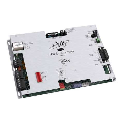
Carrier TeLINK User manual

Overview and Configuration Manual
TeLINK

Overview and Configuration Manual
TeLINK

ThisdocumentisthepropertyofCarrierCorporationandisdeliveredon
the express condition that it is not to be disclosed, reproduced in whole
or in part, or used for manufacture by anyone other than Carrier
Corporation without its written consent, and that no right is granted to
disclose or so use any information contained in said document.
Carrierreservestherighttochangeormodifytheinformationorproduct
described without prior notice and without incurring any liability.
U.S. Robotics is a registered trademark of U.S. Robotics, Inc.
© 1999, Carrier Corporation

The TeLINK Overview and Configuration Manual is catalog number
808-971, Rev. 11/99. It replaces the TeLINK Overview and
Configuration Manual 808-971, Rev. 6/97.
The revisions are listed below.
Section/Chapter Changes
Configuration 1. Added a note regarding alarm acknowledgement
operation to the Alarm Processing Definition
Table's Alarm Acknowledger decision.
2. Also added a note to the Alarm Processing
Definition Table's Alarm Threshold, Beeper
Threshold decision explanation.
Maintenance 3. Modified the TeLINK Maintenance Table's
Alarm Buffer Full decision.
Appendix A, Handling of 4. Revised Figure 12, Alarm Handling at a
Outgoing Alarms from Monitored Site.
Local Network
Manual
Revisions
iii

iv

Contents
v
Introduction .......................................................................... 1
About this Manual...................................................... 1
TeLINK...................................................................... 2
Operating Characteristics .................................................. 5
Control Module .......................................................... 5
TeLINK Configuration Tables................................... 9
TeLINK Maintenance Tables................................... 12
Sequence of Operation ............................................. 13
Configuration ..................................................................... 17
Alarm Processing Definition
(ALARMDEF) Table ............................................... 17
Controller Identification (Ctlr-ID) Table ................. 20
Modem Configuration (MODEMCFG) Table ......... 20
Monitoring Center Definition
(MONTRDEF) Table ............................................... 21
TeLINK Configuration (RCSI_CFG) Table ............ 23
Occupancy Configuration (OCCPC01S)
Table......................................................................... 25
Maintenance ...................................................................... 27
Alarm Maintenance (ALARMMNT) Table............. 27
Monitoring Center Maintenance
(MONCTMNT) Table.............................................. 28
TeLINK Maintenance (RCSI_MNT) Table............. 29
Configuration Sheets ......................................................... 33

vi
Appendix A ........................................................................ 39
Handling of Outgoing Alarms
from Local Network................................................. 39
Appendix B ......................................................................... 40
ComfortWORKS or Building
Supervisor-Initiated Calls ........................................ 40
Appendix C ........................................................................ 41
Table Configuration for
Transmitting Alarms ................................................ 41
Appendix D ........................................................................ 43
Table Configuration for
Receiving Alarms..................................................... 43
Appendix E ......................................................................... 44
TeLINK-Generated Alarms and Alerts.................... 44
Index ................................................................................... 45
Figures Figure 1 Example of TeLINK Linking
Two CCNs .............................................. 3
Figure 2 TeLINK .................................................. 6
Figure 3a Occupied State — Alarms
Reported to a Monitoring Site .............. 11
Figure 3b Unoccupied State — Alarms
Reported to a Different
Monitoring Site..................................... 11

vii
Figure 4 Alarm Processing Definition
(ALARMDEF) Table ........................... 17
Figure 5 Modem Configuration
(MODEMCFG) Table .......................... 20
Figure 6 Monitoring Center Definition
(MONTRDEF) Table ........................... 21
Figure 7 TeLINK Configuration
(RCSI_CFG) Table............................... 23
Figure 8 Occupancy Configuration
(OCCPC01S) Table .............................. 25
Figure 9 Alarm Maintenance
(ALARMMNT) Table .......................... 27
Figure 10 Monitoring Center Maintenance
(MONCTMNT) Table .......................... 28
Figure 11 TeLINK Maintenance (RCSI_MNT)
Table ..................................................... 29
Figure 12 Alarm Handling at a Monitored
Site ........................................................ 39
Figure 13 ComfortWORKS or
Building Supervisor-Initiated Calls
to a Monitored Site ............................... 40

viii

Introduction

1
Introduction
This manual contains information about the functions of TeLINK
and how the user configures the TeLINK control module to perform
those functions.
The manual is divided into the following sections:
• Introduction
• Operating Characteristics
• Configuration
• Maintenance
• Configuration Sheets
• Appendixes
The Introduction consists of this description of the manual and an
overview of TeLINK.
The Operating Characteristics section contains a description of the
TeLINK hardware, a description of how TeLINK operates, and a
summary description of its configuration tables.
The Configuration section contains detailed lists of the decisions for
each TeLINK configuration table. Each list entry includes the
decision’s purpose, the range of values that may be used, and the
default values that will appear in the decision if it is not configured
by the user.
The Maintenance section contains detailed lists of the decisions for
each TeLINK maintenance table. Each list entry includes the
decision’s purpose and the range of values that may be displayed.
The Configuration Sheets section consists of a list of configuration
decisions arranged in a table format. These sheets are provided so
that they may be photocopied for use as worksheets and hard copy
records when configuring TeLINK.
The Appendixes section contains flowcharts that illustrate how
TeLINK handles alarms and calls initiated by ComfortWORKS and
the Building Supervisor. This section also specifies how to config-
ure TeLINKs at monitored and monitoring sites to transmit or
receive alarms. TeLINK-generated alarm and alert messages are
also discussed.
About this Manual

2
The TeLINK control module serves as an interface device between a
Carrier Comfort Network (CCN) and a modem. The module and
modem enable the CCN to communicate over telephone lines with
other similarly equipped CCNs.
In this manual, the terms monitoring site and monitored site are used
to refer to two CCNs linked together as illustrated in Figure 1.
The monitoring site is the CCN that can:
• receive alarms and alerts from the monitored site.
• generate ComfortWORKS and Building Supervisor-initiated
calls for the purpose of retrieving data, for example, history and
runtime reports.
• allow user-initiated calls for the purpose of controlling and/or
monitoring remote system elements.
• trigger the self-health diagnostic check once a day.
The monitored site is the CCN that can:
• send alarms and alerts to the monitoring site.
• dial a numeric-type beeper service in response to alarms.
• receive ComfortWORKS and Building Supervisor-initiated calls
for the purpose of retrieving data.
• receive ComfortWORKS and Building Supervisor-initiated calls
for the purpose of controlling and/or monitoring system ele-
ments.
• provide Network Directory Services (NDS) functions.
TeLINK

3
Figure 1
Example of TeLINK Linking
Two CCNs
ComfortWORKS
(Optional)
TeLINK
System
Elements
TeLINK
ComfortWORKS
Carrier
Comfort
Network
(CCN)
System
Elements
(Optional)
Monitored Site
Monitoring Site
Carrier
Comfort
Network
(CCN)

4

Operating
Characteristics

5
TeLINK is a device similar in appearance to an external modem. It
can be placed on a desktop or inside a standard NEMA enclosure. It
consists of an electronic control module with a PCMCIA-Type II
modem card and power supply. The modem card and power supply
can be purchased with the module or separately. The module is
equipped with specialized software that enables it to perform its
communication tasks.
TeLINK can dial into or receive calls from another TeLINK, Auto-
dial Gateways I, II, and III, and it can dial into and connect with a
Network Access Module (NAM).
The control module is shown in Figure 2 on the following page. It
has the following features:
• LED indicators for processor status, CCN communication status,
and modem status
• RS-485 serial communication port for CCN connection
• PCMCIA Type II card modem connector
• Network Service Tool connector
The CCN connector must be connected to a primary CCN Commu-
nication Bus (Bus 0).
A TeLINK’s address on its CCN Communication Bus must have a
system element number within the range of 1 to 63. This limitation
is imposed by its operating software. The TeLINK’s default address
is Bus # 0, Element # 50.
There are three LEDs on the front of the control module that indi-
cate system status. They are described in the following table.
LED Indicates
Red Control module status
Green Modem status
Yellow Data transmission status
Operating
Characteristics
Control Module
LED Indicators

6
Figure 2
TeLINK (front and
back views)
Back
Front

7
LED functions are described in the table below.
LED State Status
Red blinking control module
functioning properly
on/off control module not
functioning properly
Green off modem not installed
on modem installed,
configured, on-hook
blinking attempting to connect
(on 1 sec., off 1 sec.)
blinking connected
(on 1 sec., off 3 sec.)
blinking (rapidly) on whenever
transmitting data
Yellow off no activity on CCN
blinking (rapidly) activity on CCN
The TeLINK module features a Network Service Tool connector on
the front, and CCN bus, power, and modem connectors on the back.
They are described in the table below.
Connector Type
Service Tool RJ-11 modular phone jack
Power 0.1 inch (2.5 mm) miniature
power jack
CCN Bus three pin, screw terminal
Modem PCMCIA Type II
Connectors

8
Pin assignments for the Service Tool and the CCN Communication
Bus connectors are described below.
Connector Signal Pin
Service Tool Unused 1
Data (+) 2
Signal ground 3
Unused 4
Data (-) 5
Unused 6
CCN Bus Data (+) 1
Signal ground 2
Data (-) 3
TeLINK is designed to use a factory- or user-supplied PCMCIA
(Type II) modem, which supports the AT command set and response
codes. The default configuration is for the U.S. Robotics® 28800
modem type.
TeLINK requires a factory- or user-supplied external power supply.
The power supply should be rated for a minimum of 500 mA at 9
Vac (unregulated).
Note: The U.S. Robotics requirement for the 28800 modem type
does not exceed 250 mA, and the module does not draw
more than 250 mA from the power supply. Modem types
with greater power requirements may need a larger power
supply.
Modem for Use
with TeLINK
Power Supply for
Use with TeLINK

9
The user configures TeLINK by means of the following tables:
Alarm Processing Definition Table
Controller Identification Table
Modem Configuration Table
Monitoring Center Definition Table
TeLINK Configuration Table
Occupancy Table
The user configures these tables from a ComfortWORKS, the
Building Supervisor, or a Network Service Tool.
For descriptions of the decisions in each table, refer to the Configu-
ration section. The purpose of each table is summarized on the
following pages.
The Alarm Processing Definition Table (ALARMDEF) contains
decisions used to specify the following:
• Conditions that will enable alarm processing
• Whether automatic diagnostics are enabled
• Building number and customer code
The Automatic Diagnostic Self-Health Check function is triggered
by the Diagnostic Alert Target Hour configuration entry. If the
value entered is 0then this function is disabled. Otherwise, the
function will run automatically once a day. This function initiates
an alarm call to the occupied monitoring center to enable monitoring
center personnel to confirm that the remote site is active. The entry
in this decision establishes a time range for this alarm to occur,
which will happen at a random time up to 255 minutes before the
targeted hour.
Example
If the target hour is 9:00 am, the alarm will occur each day between
4:45 am and 9:00 am.
Example
If the hour is 2:00 am, the alarm will occur each day between
midnight and 2:00 am.
TeLINK
Configuration
Tables
Alarm Processing
Definition Table
Table of contents
Other Carrier Network Hardware manuals
Popular Network Hardware manuals by other brands

Cabletron Systems
Cabletron Systems Netlink FRX8000 Installation and setup guide

D-Link
D-Link DNS-1200-5 user manual

Lutron Electronics
Lutron Electronics Smart Bridge quick start guide

Bosch
Bosch VIP X1600 M4S Installation and operating manual

SRS Labs
SRS Labs SIM921 Operation and service manual

LTS
LTS LTN8932H-P24 user manual