3.1 95-86005
CAMERA LOCATION
Cameras should be positioned to provide the best
unobstructed view of the area to be monitored. If the
camera is to monitor the same area as the detector,
it should be mounted as close to the detector as
practical. The following factors should also be taken into
consideration:
• Be sure that the unit is easily accessible for cleaning
and other periodic servicing.
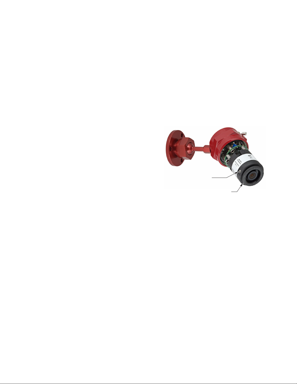
• Care must be taken to ensure that dirt, moisture or
other contaminants will not accumulate on the lens
and obscure the vision of the camera. If possible,
point the camera slightly downward.
• The camera should be mounted on a rigid surface in
a low vibration area.
• The camera should not be placed where rising
combustion products can obscure its vision. If
dense smoke is expected to accumulate at the onset
of a fire, the camera should be mounted on a side
wall at least a few feet (approximately 1 meter) down
from the ceiling.
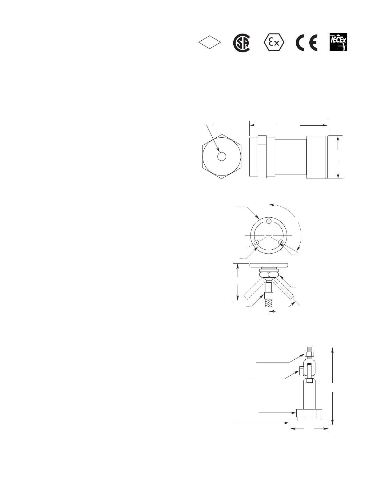
CAMERA MOUNTING
Install the swivel mounting bracket assembly on the wall.
The installation surface should be free of vibration and
suitable to receive 1/4 inch (M6) screws with a length of
at least 1 inch (25 mm), and have sufficient capacity to
hold the camera and bracket weight.
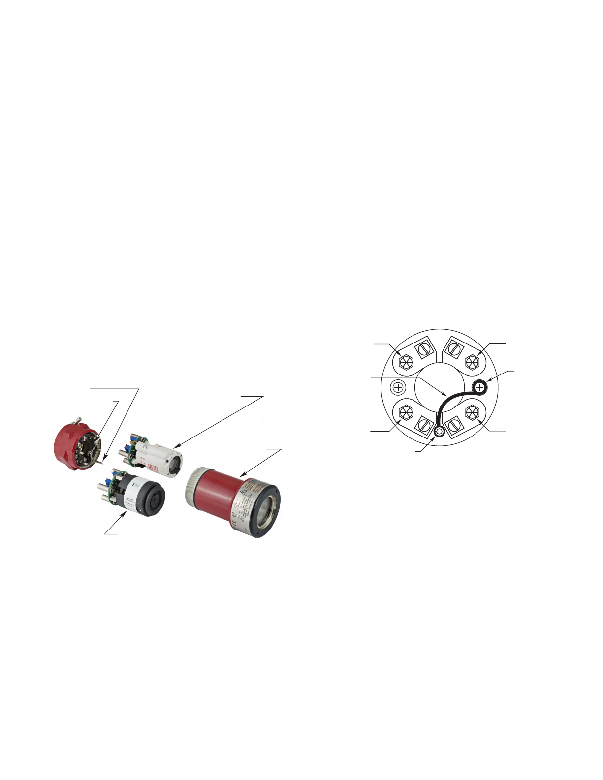
WIRE SIZE AND TYPE
General
The preferred wiring system for the xWatch Camera
Model X7050 utilizes unshielded twisted pair for the
video signal. Power wiring requires a wire gauge large
enough to ensure that 18 Vdc is available to the device
at all times.
NOTE
In applications where the wiring cable is installed
in conduit, the conduit must not be used for wiring
to other electrical equipment.
Video Cable Considerations
Proper video cable will ensure that the best quality video
is displayed on a remote monitor. Because composite
video frequencies span the range of 25 Hz to 6 MHz,
most cables will display transmission line characteristics.
Ensure that the same cable type (impedance) is used
throughout the entire length. For example, do not mix
twisted pair cable and coaxial cable without using a
balun for matching. In addition, the monitor end must
be properly terminated. Failure to properly implement
the video cabling system may result in smearing (loss
of detail) and/or loss of color and/or loss of picture sync.
The camera employs a balanced differential video
driver designed to drive twisted pair cable of 100 ohm
impedance. The best video performance in terms of
distance, video quality, and cost is attained using a 22
AWG to 16 AWG unshielded twisted pair cable of 100
ohm impedance. The wiring can be Category 2 or better,
stranded or solid.
The monitor end must terminate the video cable with 100
ohms. Most monitors have a built in termination resistor.
If the monitor uses 75 ohms instead of 100, a balun or
other matching network must be used.
There are manufacturers who support driving many
types of cable systems using active transceivers that
compensate for cable losses.
Galvanic isolation of the video may also be necessary
to avoid horizontal bars caused by line frequency
interference. This may be accomplished using isolating
active transceiving systems or passive video isolation
transformers/baluns. Specify a baseband video isolation
system with a frequency response of at least 25 Hz to 6
MHz. Small cable TV transformers will generally not work
as their frequency response is not low enough.
Power Cable Considerations
To ensure proper operation, a minimum of 18 Vdc is
required at the terminal block of the camera, considering
a worst case current draw of 0.156 Amps (2.8 Watts).