W
TF
N
lens cable
ALC lens connector
Lens mounting hole
Lens (recommended)
Protruded portion from
mount face: ø20 mm
{25/32 inches} or less
Protruded portion from ange
face: 4.5 mm {5/32 inches}
or less
Installation
The installation tasks are explained using 5 steps.
Step1
Make sure all items are prepared
before beginning installation.
Step2
Mount the lens to the cam-
era.
Step3
Insert/remove an SD memory
card.
Step4
Mount the camera.
Step1 Preparations
To install the camera to a ceiling or wall, prepare the required mount bracket and the screws that
secure the bracket, or the anchor bolt for each installation method before starting the installation.
The following are requirement examples for the various installation methods.
Installation method Recommended screw
Minimum pull-out
strength
(per 1 pc.)
[1] For mounting on ceiling*1
(Mount bracket: approx. 260 g
{0.57 lbs}, camera: 400 g {0.88 lbs},
lens: 40 g {0.09 lbs})
M6 or M8 screws x 4*1 562 N {126 lbf}*2
M4 x1(for the safety wire)
24.5 N {5.5 lbf}
[2] For mounting on wall*1
(Mount bracket: approx. 420 g
{0.93 lbs}, camera: 400 g {0.88 lbs},
lens: 40 g {0.09 lbs})
M6 or M8 screws x 4*1 724 N {163 lbf}*2
M4 x1(for the safety wire)
24.5 N {5.5 lbf}
[3] When using the tripod mount
base (A)*3 — —
*1 The number of required screws or anchor bolts varies depending on the specications
of the mount bracket (locally procured). Refer to the operating instructions of the mount
bracket (locally procured) for information about how to mount the mount bracket.
*2 Make sure that the screws or anchor bolts separately procured when locally procuring a
mount bracket for the ceiling or wall are capable of supporting the total weight (including
the moment force when mounting to a wall).
*3 Size of the bracket mounting hole: "1/4-20UNC camera tripod mounting hole (depth 9 mm
{11/32 inches})"
IMPORTANT:
● The installation area shall be strong enough to hold the camera and camera mount
bracket.
●
The camera mount bracket (locally procured) shall be mounted on the foundation part of
the construction or a part with adequate strength.
● Select screws according to the material of the ceiling that the camera will be mounted
to. In this case, wood screws and nails should not be used.
● If a ceiling board such as plaster board is too weak to support the total weight, the
area shall be sufficiently reinforced.
Step5
Connect and adjust the
camera
The lens section is not included with the camera. It is possible to mount a 1/3 type
video camera lens to the camera.It is recommended to use a recommended high-res-
olution lens especially when the illuminance level of the photographic subject is low
and the camera is used with the lens iris open. If a lens other than the recommended
lens below is mounted and the camera is used at a resolution of 1280 x 720 or higher,
the camera cannot achieve full performance of high resolution.
Refer to our website (http://security.panasonic.com/pss/security/support/info.html) for
further information about the recommended lens.
* When using a lens made by other companies, use a lens that has a protruded por-
tion from the mount face of ø20 mm {25/32 inches} or less and a protruded portion
from the ange face of 4.5 mm {5/32 inches} or less. Lenses without a focus adjust-
ment mechanism and zoom lenses cannot be used.
q Remove the cover lm attached to the
lens mounting hole of the camera.
w Slowly rotate the lens clockwise to
mount the lens and connect the lens
cable to the ALC lens connector of the
camera.
1 3
2 4
ALC lens connector
Step2 Mount the lens to the camera
When using an SD memory card, go through the following procedure before installing
the camera. When removing an SD memory card, reverse the procedure.
Refer to the Operating Instructions on the provided CD-ROM for further information
about the SD memory card settings.
[1] Open the slide cover on the side of the camera, insert an SD memory card fully into
the SD memory card slot until a click is heard.
● Insert the SD memory card with its label facing down.
[2] Loosen the screw (M3) of the clamp for the SD memory card, and slide the clamp to
the middle, then tighten the screw.
(Recommended tightening torque: 0.19 N·m {0.14 lbf·ft})
[3] Close the slide cover on the side of the camera.
●
To remove the SD memory card, hold down
the SD ON/OFF button for about 2 sec-
onds. When the flashing SD MOUNT indi-
cator goes out, you can remove the SD
memory card.
●
After the SD memory card has been
replaced, press the SD ON/OFF button,
and make sure the SD MOUNT indicator is
continually lit.
● If you do not press the SD ON/OFF button
after replacing the SD memory card, the SD
MOUNT indicator is continually lit approxi-
mately 5 minutes later.
Connect the safety wire (E: accessory)
● When securing the camera using a separately procured bracket, use the xing screw
(M4, locally procured), and the safety wire, washer, and spring washer (accessories).
[1] Engage the safety wire (accessory) with the wire engaging hole.
[2] Secure the safety wire lug (ac-
cessory) to the camera mount
screw hole with the wire lug xing
screw (D) (accessory).
(Recommended tightening
torque: 0.39 N·m {0.29 lbf·ft})
When using the tripod
mount base (A)
● Use the tripod mount base when
mounting the camera to raise the
camera mounting position.
● Remove the screw from the camera's
bottom side. Please store the
removed screw in a safe location for
when you choose to remove the tripod
mount base, as they will not be need-
ed from this point onwards.
[1] Secure the tripod mount base to the
bottom side of the camera using 2
xing screws. (Recommended tight-
ening torque: 0.39 N·m {0.29 lbf·ft})
Size of the mounting hole: "1/4-
20UNC camera tripod mounting hole
(depth 9 mm {11/32 inches})"
Clamp for SD
memory card
SD memory card
* Label face downward
Safety wire (accessory)
Wire engaging hole
After mounting
Part A
Safety wire lug
(C) (accessory)
q Pass part A through the wire
engaging hole
Clamp for SD
memory card
Screw of the clamp
for SD memory card
Tripod mount base
(accessory)
Bottom side
Fixing screws
1/4-20UNC camera tripod
mounting hole (depth 9 mm
{11/32 inches})
* The wire image mounted to the safety wire lug
in [1] of "Connect the safety wire" is not shown.
* The wire image mounted to the safety wire lug in
[1] of "Connect the safety wire" is not shown.
Wire lug xing
screw (accessory)
Safety wire lug
(accessory)
Fixing screw hole
Step3 Insert/remove an SD memory card Step4 Mount the camera Step5 Connect and adjust the camera (Continued)
Step5 Connect and adjust the camera
Note:
● The most common use of a varifocal lens and a zoom lens
Note that the adjustment method is different depending on the type. For fur-
ther information, refer to the operating instructions for the lens to be used.
When using 8x or 10x lens, adjust the back focus after positioning the
zoom ring at the "W" end and positioning the focus ring at a step short of
the "F" end. SPN311
When using 2x or 3x lens, adjust the back focus after positioning the
zoom ring at the "T" end and positioning the focus ring at a step short of
the "F" end. SPN311
● Depending on the lens to be used, if the zoom ring is fully rotated in the
"W" direction, the periphery may become dark. In such a case, rotate the
zoom ring in the "T" direction for readjustment.
● When images in the near-infrared light area change from the color mode
to the black & white mode, out-of-focus may be occurred according to the
nature of optical property. In this case, the focus can be corrected by
selecting "Auto" or "Preset" for "Adjusting method" on the setup menu
(The focus will not automatically be adjusted according to the illumination
level change once the focus is corrected.) Refer to the Operating
Instructions (included in the CD-ROM) for how to configure the "Adjusting
method" setting on the setup menu. SPN311
● When shooting the following subjects, it may have difficulty adjusting the
back focus position automatically. In this case, adjust the back focus
position manually from the setup menu. Refer to the Operating
Instructions (included in the CD-ROM) for how to perform the auto back
focus function from the setup menu. SPN311
● When shooting the following subjects or in the following places, close the
"FOCUS ADJUSTMENT" menu by pressing the focus assist (F.A.) but-
ton, and adjust the focus to obtain the best focus position while monitor-
ing images from the camera. SPN310
● Subj. moves frequently
● Subj. with large illuminance change
● Subj. with low illuminance
● Subj. through a window
● Subj. with less contrast such as white wall
● Subj. with heavy flicker
● In case the angular field of view has changed during adjustment, close
the "FOCUS ADJUSTMENT" menu by pressing the focus assist (F.A.)
button. (When the angular field of view changes, the indicator values of
"PEAK HOLD" and "INDICATOR" also change.) After fixing the angular
field of view, open the "FOCUS ADJUSTMENT" menu by pressing the
focus assist (F.A.) button, then adjust the focus again. SPN310
IMPORTANT:
● Be sure to rotate and secure the camera mount bracket. Rotating the camera plac-
es a large burden on the camera mount bracket, and may cause damage.
● Attach the safety wire in a position higher than the camera and the mount bracket.
● Attach the safety wire so that if the camera were to become detached, it would not
fall on nearby people.
IMPORTANT:
● Mount the bracket in a position higher than 2.7 m {8.86 feet} from the floor.
IMPORTANT:
● Be sure to rotate and secure the camera mount
bracket. Rotating the camera places a large
burden on the camera mount bracket, and may
cause damage.
● The safety wire shall be adjusted to remove slack.
● The distance from the camera to the ceiling
changes depending on the tilt angle of the cam-
era. Attach the safety wire in a position accord-
ing to the tilt angle of the camera.
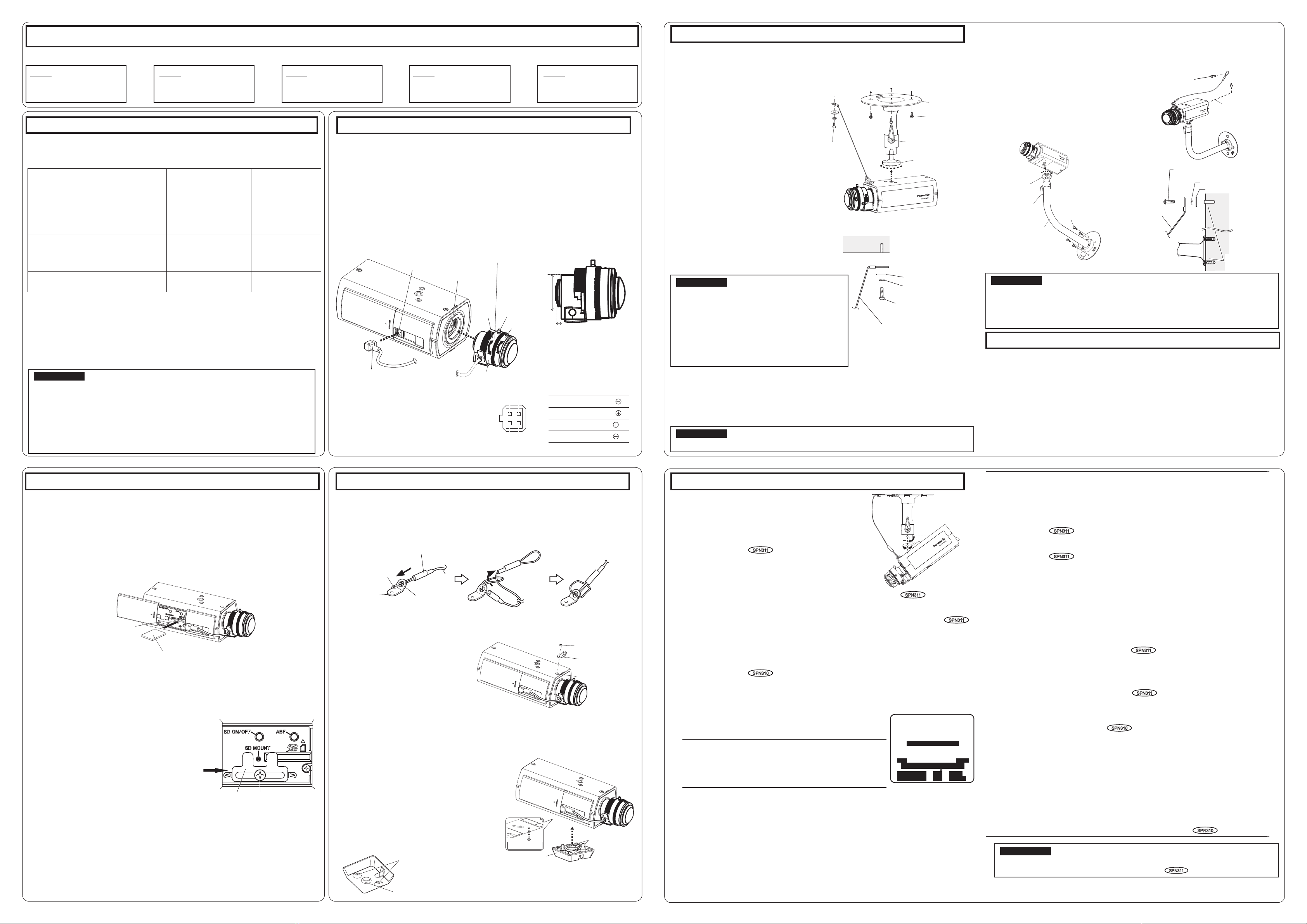
For mounting on ceiling
[1] Mark the position of holes to be made for the ceiling mount bracket (locally procured) on
the attachment position of the ceiling, and make those holes for attachment.
Determine the hole diameter and hole depth according to the specications of the screws
or anchor bolts to be used.
For mounting on wall
[1] Mark the position of holes to be made for the wall mount bracket (locally procured) on the
attachment position of the wall, and make those holes for attachment.
Determine the hole diameter and hole depth according to the specications of the screws
or anchor bolts to be used.
[2] Secure the wall mount bracket (locally
procured) using separately procured
screws or anchors.
[3] Loosen the camera mount bracket xing
mechanism to freely move the camera
mount bracket.
Align the screw thread with the xing
screw hole of the camera, and rotate
the camera mount bracket to secure
the camera. Tighten the camera mount
bracket xing mechanism and secure
the camera mount bracket.
* The tripod mount base (accessory) is
not used.
[4]
Attach the safety wire to the foundation
area of the architecture or where sufcient
strength is assured. Prepare the xing
screws according to the material of the area
where the safety wire is to be installed.
[2]
Secure the ceiling mount bracket
(locally procured) using separately
procured attachment xing screws or
anchors.
[3]
Loosen the camera mount bracket xing
mechanism to freely move the camera
mount bracket.
Align the screw thread with the xing
screw hole of the camera, and rotate
the camera mount bracket to secure
the camera.
Tighten the camera mount bracket x-
ing mechanism and secure the camera
mount bracket.
* The tripod mount base (accessory) is not used.
[4] Attach the safety wire to the foundation area of
the architecture or where sufcient strength is
assured. Prepare the xing screws according to
the material of the area where the safety wire is
to be installed.
If the camera angle is changed when the camera mount
bracket xing mechanism is tightened, excessive force
is applied to the camera mount bracket and camera,
which may damage them.
After adjusting the camera angle, make sure to tighten the
camera mount bracket xing mechanism securely again.
[1] Connecting wires
Connect the necessary cables/lead wires according to the procedure of "Making
connections". (When power is supplied by PoE, the camera is turned on when a
LAN cable is connected. Make sure to connect the LAN cable after turning off the
power of hub and router.)
[2] Adjusting the camera angle
Connect the adjustment monitor to the MONITOR OUT terminal of the camera
with the RCA pin cable (locally procured).
Loosen the camera mount bracket xing mechanism on the camera mount bracket,
and then check the adjustment monitor to adjust the camera angle.
When adjusting the camera angle, make sure to loosen the camera mount bracket
xing mechanism on the camera mount bracket before making adjustments.
[3] Adjusting the focus SPN311
q First, reset the back focus position by hold-
ing down the auto back focus button
for 5 seconds or more when the power is on. (This
operation can also be performed on the setup menu.
Refer to the Operating Instructions (included in the CD-ROM).) SPN311
w Manually adjust the angle of view and focus coarsely by adjusting the zoom and
focus of the lens, and then press the auto back focus button on the side of the cam-
era (page 1) or perform the auto back focus function from the setup menu. SPN311
Refer to the Operating Instructions (included in the CD-ROM) for how to perform
the auto back focus function from the setup menu.
* How to take a wide depth of field: When focus is desired on entire near or
distant subjects, select indoor scene mode, or adjust the focus to the midrange
position using manual focus adjustment.
Adjusting the focus SPN310
The focus is adjusted using the focus assist function.
The angle of view and focus can be adjusted in accordance with the distance between
the camera lens and a photographic subject. These adjustments shall be performed
together with the camera angle adjustment.
q
Loosen the zoom lock knob, and adjust the angle of view
(angular eld of view) in accordance with the photographic
subject by moving the zoom lock knob and focus ring.
Note
●
The focus may not be adjusted appropriately when the
zoom lock knob is positioned at the "W" (or "T") end.
In this case, adjust the focus again by slightly moving
the zoom lock knob to the direction of "T" (or "W").
w Fasten the zoom lock knob.
e Press the focus assist button.
→ "FOCUS ADJUSTMENT" menu will be displayed.
The focus assist function will be activated to perform the optimum adjustment.
r When the focus ring is positioned near the best focus position, the position will
automatically be memorized as the "PEAK HOLD" position.
t Loosen the focus lock knob and move the focus ring, the current focus position will
be indicated on "INDICATOR". Adjust the focus position so that the indicator value
goes close to the "PEAK HOLD" position.
y When the indicator value goes to the best focus position, "BEST FOCUS" will be
displayed at the lower right corner of the screen, then fasten the focus lock knob.
u Press the focus assist button again to close the "FOCUS ADJUSTMENT" menu.
(No operation for 3 seconds also closes the menu.)
IMPORTANT:
● After performing basic adjustments, make sure to press the auto back focus
button once to perform detailed adjustments. SPN311
Step4 Mount the camera (Continued)
Washer (F)
(accessory)
Spring washer (G)
(accessory)
Recommended screw M4
Minimum pull-out strength
24.5 N {5.5 lbf}
Safety wire
Ceiling
Pin No.
1 Dump
2 Dump
3 Drive
4 Drive
Safety wire
Recommended screw M4
Minimum pull-out strength 24.5 N {5.5 lbf}
Foundation part of
construction or part
with adequate strength
Wall
Washer (F) (accessory)
Spring washer (G) (accessory)
●After connecting the camera, refer to "Configure the settings of the cam-
era" (leaflet) and perform the camera settings.
Fixing screws
Wall mount bracket
(example)
Attachment xing
screws
M6 or M8 x4
(locally procured)
Camera mount bracket
fixing mechanism
Camera mount
bracket
w Pass part A through the
other loop of the wire
Attachment xing
screws M4 x1
(locally procured)
Higher than the
camera and wall
mount bracket.
Ceiling mount
bracket (example)
Attachment xing
screws M6 or M8 x4
(locally procured)
Camera mount
bracket
Camera mount brack-
et xing mechanism
Recommended
screw M4
Minimum pull-out
strength
24.5 N {5.5 lbf}
Focus ring
Zoom lock knob
FOCUS ADJUSTMENT
LOW HIGH
............|.......
INDICATOR 620 BEST
PEAK HOLD 635 FOCUS


