manuals.online logo
Brands
  1. Home
  2. •
  3. Brands
  4. •
  5. Honeywell
  6. •
  7. Security Camera
  8. •
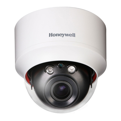
  9. Honeywell HD3VC4HR User manual

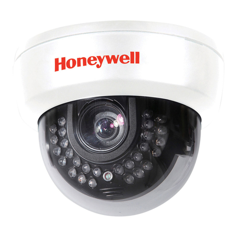
Honeywell HD3VC4HR User manual

Ø
110mm
Ø90mm
Ø80mm
PACKING LIST
1. Dome Camera with fitted
DD Vari-focal Lens
2. Bare tinned end PSU
connecting lead.
3. Instruction Manual
4. Drilling Template
CAMERA SPECIFICATIONS
Model No. HD3VC4A HD3VC4HR HD3VM4A
Format NTSC NTSC EIA
Scanning Element 2:1 Interlace –H: 15. 750 KHz –V :60 Hz
Image Picture
Element 1/3” High Sensitivity CCD
Effective Picture
Element 510(H) x 492(V) 768(H) x 494(V) 510(H) x 492(V)
Resolution 330 Horizontal
TV Lines 470 Horizontal
TV Lines 380 Horizontal
TV Lines
Minimum
Illumination 1.5 Lux @F1.6 2.0 Lux @ F1.6 0.5 Lux @F1.6
S/N Ratio 48 dB (AGC OFF) 50 dB (AGC OFF) 52 dB (AGC OFF)
3” Bubble Tint Colored ; Optical perfect Max. 1F loss
Backlight
Compensation On / Off Switch
AGC On / Off Switch
Sync System Internal / Line Lock
Gamma
Compensation 0.45
Video Output 1.0 Vp-p, 75 ohm Unbalanced
White Balance Automatic White Balance N/A
ATW Range 2700K –9100K 2700K –9100K N/A
Power Range 12 Vdc ±10% / 24 Vac ±10% SPS
Power Consumption
2.8 W ( Max )
Operating
Temperature -5°C ~ +45°C(23°F ~ 113°F)
Less than 80% Relative Humidity
Dimensions
(Height x Diameter) Height: 80 mm (3.15”)
Diameter: 110 mm (4.33”)
Weight 180 g (6.35 ounces) Net
LENS SPECIFICATIONS
Focal length 3.8 -9.5 mm
Tele: F2.0~360
Wide: F1.3~360
4.0 -9.0 mm
Tele: F2.4~360
Wide: F1.6~360
3.8 -9.5 mm
Tele: F2.0~360
Wide: F1.3~360
Field-of-View 4.0 mm ~ 9.0 mm: Horizontal: 71.0°~31.6° / Vertical:51.8°~23.6°
3.8 mm ~ 9.5 mm: Horizontal: 71.0°~31.6° / Vertical:51.8°~23.6°
Rev. B 5HDMU000923
Video Systems
www.honeywellvideo.com
1-800-796-CCTV
© 2004 Honeywell International Inc.
Rev. B 6HDMU000923
HD3VC4HR / HD3VC4A / HD3VM4A
3” Varifocal Dome
INSTRUCTION MANUAL
HD3VC4HR –High Resolution Color Miniature Dome Camera
HD3VC4A –Standard Resolution Color Miniature Dome Camera
HD3VM4A –Standard Resolution Monochrome Miniature Dome
Camera
FEATURES
•Compact and lightweight design.
•Integrated 4-9 mm Varifocal Lens allows for easy
installation and adjustments.
•Hi-speed F1.6 lens provides excellent low light
performance.
•DSP controls for Back Light Compensation,
White Balance, and Gain Control.
•Flickerless mode improves image in fluorescent
lighting conditions.
•Automatic Internal sync selection
(voltage dependant).
•Thin optical distortion free bubble.
•Manual pan / tilt / 360° rotation mechanism.
•Wall or a ceiling installation.
•Video cable with BNC included.
•2 wire power connection.
•Variable voltage switched mode power supply unit
with 12 VDC or 24 VAC operation with line lock.
Rev. B 1HDMU000923
PRECAUTIONS
1. Do not attempt to disassemble the camera. To prevent
electric shock, do not remove screws or cover. There are
no user-serviceable parts inside. Refer servicing to
qualified service personnel.
2. Handle the camera with care. Do not abuse the camera.
Avoid striking or shaking it. Improper handling or storage
could damage the camera.
3. Do not expose the camera to rain or moisture, or try to
operate it in wet areas. Take immediate action should the
camera become wet. Turn power off and refer servicing
to qualified service personnel. Moisture can damage the
camera and also create the danger of electric shock.
4. Whether or not the camera is in use, never face it towards
the sun. Use caution when operating the camera in the
vicinity of spotlights or other bright lights and light
reflecting objects.
5. Do not operate the camera beyond its temperature,
humidity or power source ratings. Use the camera under
conditions where temperatures are within –5°C ~ +45°C
(23°F ~ 113°F), and relative humidity is below 80%
(non-condensing).
6. When the camera is not in use, ensure the lens is kept
properly in place to protect the CCD sensor.
Bubble
Camera
body
Power lead
Coaxial video
cable
Rev. B 2HDMU000923
INSTALLATION
1. Creating a Hole in the Ceiling or Wall
Use the supplied template to mark
the appropriate mounting position
on the ceiling or the wall.
Make three holes for the screws
affixing the camera body, and one
additional hole for the power and
video cables.
2. Connecting the Cables
Camera
1. If required, use the supplied flying lead, l.
2. The center pin of the power connector k✟is +12 VDC
(red) and the sheath is 0 VDC (black). At 24 VAC the unit
is not polarity conscious –connect either way.
3. Connect the video cable to the dome at connector j.
ATTENTION
1. Check that power is off before handling the power cable.
2. Check 12 VDC polarity before connecting to the PSU.
Wrong polarity may damage camera.
3. Mounting the Camera Body
1. Remove the body cover, and mount the camera body to
the ceiling or wall.
2. Align the housing to the predrilled holes, and use three
screws to mount the camera body.
3. Choose screws suitable for the type of ceiling or wall
material. Counter-sunk screws with a diameter of 4mm to
5mm are recommended.
Rev. B 3HDMU000923
ADJUSTMENT
1. AGC, BLC & FL dip switch settings
Set according to lighting conditions.
Back Light Compensation (BLC) ON/ OFF:
When strong, unwanted background lighting interferes
with the clarity of important areas, turn this switch to the
“ON” position. The BLC compensates to back light
conditions in the central and lower area.
Auto Gain Control (AGC) ON/OFF: Switching the AGC
on will improve camera sensitivity in low light conditions.
Flickerless mode (FL): Used if interference from
fluorescent lighting is detected on video picture.
Color Monochrome
2. Adjusting the Camera Position
Camera body moves in three ways: Pan, Tilt, and Rotate.
Adjust the camera orientation so that the lens is aimed at
the subject.
3. Adjusting the View Angle and Focus
Use the levers to adjust the focus and field of view.
4. Adjusting the DC Iris Level
This is factory set and does not normally require
adjustment. If adjustment is required, follow these steps:
1. Turn the dipswitch Auto Gain Control (AGC) to OFF.
2. Using a suitable screwdriver, adjust the DC iris level.
3. Turn the dipswitch Auto Gain Control (AGC) to ON.
5. Completing the Adjustment and Installation
1. Carefully attach the dome cover.
2. Check connections are secure and that field of view
and focus are correct.
Rev. B 4HDMU000923
Co
lor

This manual suits for next models

2

Other Honeywell Security Camera manuals

Honeywell CAHBC720PI60V User manual

Honeywell

Honeywell CAHBC720PI60V User manual

Honeywell OptiCAM-IR Assembly instructions

Honeywell

Honeywell OptiCAM-IR Assembly instructions

Honeywell H4W2PER2 User manual

Honeywell

Honeywell H4W2PER2 User manual

Honeywell 3 inch dome camera User manual

Honeywell

Honeywell 3 inch dome camera User manual

Honeywell Performance H4D3PRV2 User manual

Honeywell

Honeywell Performance H4D3PRV2 User manual

Honeywell HD14 User manual

Honeywell

Honeywell HD14 User manual

Honeywell 720P User manual

Honeywell

Honeywell 720P User manual

Honeywell HD31H(X) User manual

Honeywell

Honeywell HD31H(X) User manual

Honeywell HD55IP User manual

Honeywell

Honeywell HD55IP User manual

Honeywell HD2FC1X User manual

Honeywell

Honeywell HD2FC1X User manual

Honeywell ACUIX Operator's manual

Honeywell

Honeywell ACUIX Operator's manual

Honeywell 3MP User manual

Honeywell

Honeywell 3MP User manual

Honeywell HCC484TPX User manual

Honeywell

Honeywell HCC484TPX User manual

Honeywell HCC334E User manual

Honeywell

Honeywell HCC334E User manual

Honeywell HCC474M User manual

Honeywell

Honeywell HCC474M User manual

Honeywell ACUIX ES User manual

Honeywell

Honeywell ACUIX ES User manual

Honeywell Lyric C1 User manual

Honeywell

Honeywell Lyric C1 User manual

Honeywell IPCAM-WOC1 User manual

Honeywell

Honeywell IPCAM-WOC1 User manual

Honeywell EQUIP HD4DIP User manual

Honeywell

Honeywell EQUIP HD4DIP User manual

Honeywell HB74H(X) User manual

Honeywell

Honeywell HB74H(X) User manual

Honeywell HWC-D101 User manual

Honeywell

Honeywell HWC-D101 User manual

Honeywell HDZ20HD User manual

Honeywell

Honeywell HDZ20HD User manual

Honeywell HISD-2201WE-IR User manual

Honeywell

Honeywell HISD-2201WE-IR User manual

Honeywell HD3UX User manual

Honeywell

Honeywell HD3UX User manual

Popular Security Camera manuals by other brands

Panasonic WV-CW970 Service manual

Panasonic

Panasonic WV-CW970 Service manual

Brickcom OB-100A Quick installation guide

Brickcom

Brickcom OB-100A Quick installation guide

Dometic PerfectView CAM11 installation manual

Dometic

Dometic PerfectView CAM11 installation manual

American Dynamics ADC723PIR operating instructions

American Dynamics

American Dynamics ADC723PIR operating instructions

Monacor TVCCD-182HCOL operating instructions

Monacor

Monacor TVCCD-182HCOL operating instructions

Axis 02462-001 user manual

Axis

Axis 02462-001 user manual

Axis Q1604 user manual

Axis

Axis Q1604 user manual

TMEZON CQ1H instruction manual

TMEZON

TMEZON CQ1H instruction manual

Grundig GCH-K0326T owner's manual

Grundig

Grundig GCH-K0326T owner's manual

Cabletech URZ0994 quick start guide

Cabletech

Cabletech URZ0994 quick start guide

EverFocus ECZ930 eZ.HD Series user manual

EverFocus

EverFocus ECZ930 eZ.HD Series user manual

AVS SENS212WIR Quick manual guide

AVS

AVS SENS212WIR Quick manual guide

Axis P8524 user manual

Axis

Axis P8524 user manual

LARSON EXPCMR-ALG-OZ-IC-1080PLE1-1227-250C-QD-15C-12.4 Quick installation and user guide

LARSON

LARSON EXPCMR-ALG-OZ-IC-1080PLE1-1227-250C-QD-15C-12.4 Quick installation and user guide

Samsung SNB-8000 user manual

Samsung

Samsung SNB-8000 user manual

YOYOMOTION YOYOCam G3 user guide

YOYOMOTION

YOYOMOTION YOYOCam G3 user guide

Cisco Small Business VC220 datasheet

Cisco

Cisco Small Business VC220 datasheet

Dahua HAC-HD3103P user manual

Dahua

Dahua HAC-HD3103P user manual

manuals.online logo
manuals.online logoBrands
  • About & Mission
  • Contact us
  • Privacy Policy
  • Terms and Conditions

Copyright 2025 Manuals.Online. All Rights Reserved.