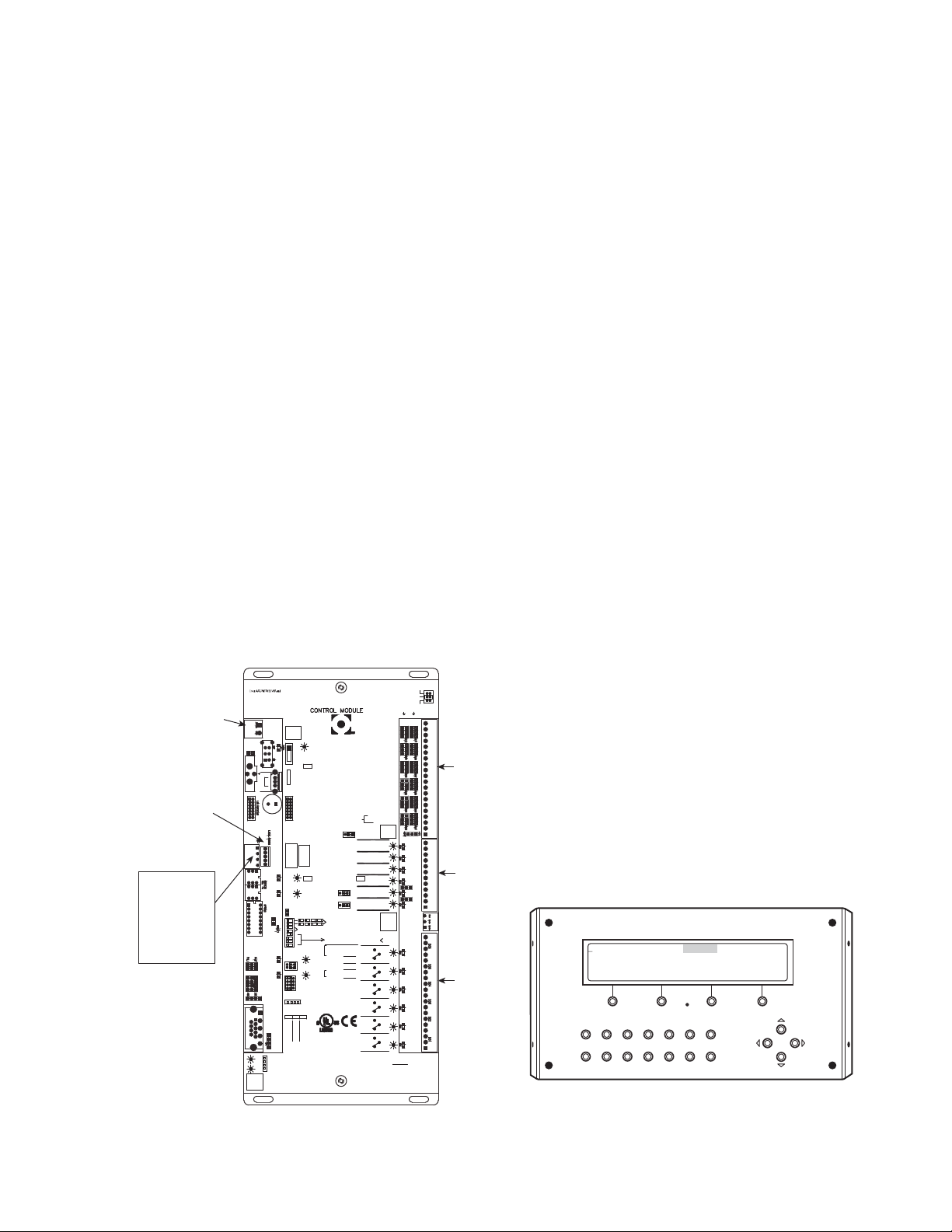
Carrier Omnizone 50XJ050 User guide

Manufacturer reserves the right to discontinue, or change at any time, specifications or designs without notice and without incurring obligations.
Catalog No. 04-53500117-01 Printed in U.S.A. Form 50XJ-2T Pg 1 8-14 Replaces: 50XJ-1T
Controls, Start-Up, Operation and
Troubleshooting
CONTENTS
Page
SAFETY CONSIDERATIONS . . . . . . . . . . . . . . . . . . . . .1,2
GENERAL . . . . . . . . . . . . . . . . . . . . . . . . . . . . . . . . . . . . . . . . 2
MAJOR SYSTEM COMPONENTS . . . . . . . . . . . . . . . 2-6
Controller Processor 6126 (PCB1). . . . . . . . . . . . . . . . 2
I/O Flex Module 8160 (PCB2) . . . . . . . . . . . . . . . . . . . . . 2
Local Interface Display . . . . . . . . . . . . . . . . . . . . . . . . . . . 2
Control Module Communication. . . . . . . . . . . . . . . . . . 2
PCB Addresses . . . . . . . . . . . . . . . . . . . . . . . . . . . . . . . . . . 2
Optional and Field-Installed
Accessory Sensors/Devices . . . . . . . . . . . . . . . . . . . 2
Wiring Control Devices. . . . . . . . . . . . . . . . . . . . . . . . . . . 5
CONTROL AND DISPLAY. . . . . . . . . . . . . . . . . . . . . . 7-17
Controller . . . . . . . . . . . . . . . . . . . . . . . . . . . . . . . . . . . . . . . . 7
BACview Interface Device . . . . . . . . . . . . . . . . . . . . . . . . 9
Log On to BACview Display . . . . . . . . . . . . . . . . . . . . . . 9
Log Out of BACview Display . . . . . . . . . . . . . . . . . . . . . 9
Change Default User Password . . . . . . . . . . . . . . . . . . 9
Automatic Self-Test . . . . . . . . . . . . . . . . . . . . . . . . . . . . . . 9
Set the Clock. . . . . . . . . . . . . . . . . . . . . . . . . . . . . . . . . . . . 11
Configure Schedules. . . . . . . . . . . . . . . . . . . . . . . . . . . . 11
Adjust Set Points. . . . . . . . . . . . . . . . . . . . . . . . . . . . . . . . 12
Configure Basic Unit . . . . . . . . . . . . . . . . . . . . . . . . . . . . 13
Unit Configuration . . . . . . . . . . . . . . . . . . . . . . . . . . . . . . 13
Unit Status . . . . . . . . . . . . . . . . . . . . . . . . . . . . . . . . . . . . . . 13
Display/Set Runtime Alarms. . . . . . . . . . . . . . . . . . . . . 13
Display Alarms and Alarm History . . . . . . . . . . . . . . 13
Set Controller Address . . . . . . . . . . . . . . . . . . . . . . . . . . 14
50XJ Variable Frequency Drive (VFD) Control
and Start-Up . . . . . . . . . . . . . . . . . . . . . . . . . . . . . . . . . . 14
VFD Control and Display . . . . . . . . . . . . . . . . . . . . . . . . 15
VFD Modes. . . . . . . . . . . . . . . . . . . . . . . . . . . . . . . . . . . . . . 15
START-UP . . . . . . . . . . . . . . . . . . . . . . . . . . . . . . . . . . . . .17,18
General . . . . . . . . . . . . . . . . . . . . . . . . . . . . . . . . . . . . . . . . . 17
Confirm the Input Power Phase Sequence . . . . . . . 17
Water Fill and Air Purge . . . . . . . . . . . . . . . . . . . . . . . . . 17
OPERATION . . . . . . . . . . . . . . . . . . . . . . . . . . . . . . . . . . 18-20
Occupancy Determination. . . . . . . . . . . . . . . . . . . . . . . 18
Fan Control . . . . . . . . . . . . . . . . . . . . . . . . . . . . . . . . . . . . . 18
Sequence of Operation. . . . . . . . . . . . . . . . . . . . . . . . . . 18
Diagnostic Features. . . . . . . . . . . . . . . . . . . . . . . . . . . . . 19
TROUBLESHOOTING. . . . . . . . . . . . . . . . . . . . . . . . . 20-27
Standard Diagnostic Features,
Alarms and Alarm Lamps . . . . . . . . . . . . . . . . . . . . . 20
50XJ Wiring Diagrams. . . . . . . . . . . . . . . . . . . . . . . . . . . 22
START-UP CHECKLIST . . . . . . . . . . . . . . . . . . CL-1, CL-2
SAFETY CONSIDERATIONS
Installing, starting up, and servicing this equipment can be
hazardous due to system pressures, electrical components, and
equipment location. Only trained, qualified installers and
service mechanics should install, start up, and service this
equipment.
When working on this equipment, observe precautions in
the literature, on tags, stickers, and labels attached to the equip-
ment, and any other safety precautions that apply. Follow all
safety codes. Wear safety glasses and work gloves. Use care in
handling, rigging, and setting this equipment, and in handling
all electrical components.
WARNING
Electrical shock can cause personal injury and death.
Shut off all power to this equipment during installation
and service. There may be more than one disconnect
switch. Tag all disconnect locations to alert others not to
restore power until work is completed.
CAUTION
This unit uses a microprocessor-based electronic control
system. Do not use jumpers or other tools to short out
components, or to bypass or otherwise depart from rec-
ommended procedures. Any short-to-ground of the con-
trol board or accompanying wiring may destroy the
electronic modules or electrical components.
WARNING
DO NOT USE TORCH to remove any component. System
contains oil and refrigerant under pressure.
To remove a component, wear protective gloves and gog-
gles and proceed as follows:
a. Shut off electrical power to unit.
b. Recover refrigerant to relieve all pressure from sys-
tem using both high-pressure and low pressure ports.
c. Traces of vapor should be displaced with nitrogen
and the work area should be well ventilated. Refrig-
erant in contact with an open flame produces toxic
gases.
d. Cut component connection tubing with tubing cutter
and remove component from unit. Use a pan to catch
any oil that may come out of the lines and as a gage
for how much oil to add to the system.
e. Carefully unsweat remaining tubing stubs when nec-
essary. Oil can ignite when exposed to torch flame.
Failure to follow these procedures may result in personal
injury or death.
Omnizone™
50XJ050-104
Water-Cooled Indoor Self-Contained Systems
with Multi-Protocol Controller 6126

2
GENERAL
This publication contains Controls, Operation and Trouble-
shooting information for the 50XJ units. The Omnizone™
packaged units are self-contained, water-cooled indoor units
for use in VAV (variable air volume) applications. Units are
equipped with Carrier multi-protocol controls. Refer to the unit
Installation Instructions for unit layout.
MAJOR SYSTEM COMPONENTS
Controller Processor 6126 (PCB1) — The cen-
tral processing unit for the Omnizone system control is the UC
Multi-Protocol XP. The controller provides general purpose
HVAC (Heating, Ventilation and Air Conditioning) control and
monitoring capability in a stand-alone or network environment
using closed-loop, direct digital controls. The controller has
been pre-programmed to work in either stand-alone or
BACnet*, MODBUS†, or Johnson N2 network system instal-
lations. The controller will also operate on a LonWorks** net-
work with an accessory LON-OC board installed.
The controller is designed to provide heating and cooling
control, loop control, scheduling, and custom programming.
The main processor provides 24 field points (12 universal in-
puts, 6 relay outputs, and 6 analog outputs). Additional points
are provided by the I/O (input/output) modules. Table 1 lists
the control inputs and outputs for all modules.
Specifications for the Multi-Protocol Controller may be
found in the Open System literature.
I/O Flex Module 8160 (PCB2) — This input/output
module is factory-installed and allows additional factory and
field points (16 inputs and 8 outputs).
The module provides the following inputs: outdoor-air tem-
perature (accessory), leaving-water temperature (accessory),
tower sump temperature (accessory), mixed-air or return-air
temperature (factory), water economizer freeze sensor (option)
or freeze thermostat (accessory), entering water temperature
(option), enthalpy sensor (accessory), filter status switch (op-
tion), phase rotation monitor (option), condenser water flow
switch (option), and compressor status (factory).
This module provides the following field digital outputs:
heat interlock (HIR), VAV terminal control (TRMCT), ventila-
tion request (VENTR), VAV terminal open (TRMOP), pump
request, tower request, and external dehumidification.
Local Interface Display — The BACview interface
display is mounted on the front of the 50XJ units. A number of
user-adjustable features are entered/changed using the display
keypad. These features described in detail in the Control and
Display section of this manual.
Control Module Communication — When power is
applied to the Omnizone™ system control panel, green power
LED (light-emitting diode) lights. Once the control program
initializes, the green RUN LED on each module should flash
on/off about twice a second and the red error (ERR) LED
should be off. The green Tx/Rx LEDS flicker when data is
communicated over the network. The green Tx/Rx LEDS near
the Xnet remote expansion port flicker when the main board
and the expansion board are communicating.
PCB Addresses — Rotary switch 1 (SW1) is used to set
each controller’s address, as well as the input/output module
address. Individual jumpers on each board are used to config-
ure the input point type. For more information, refer to Table 1
and the Optional and Field-Installed Accessory Sensors/Devic-
es section.
Optional and Field-Installed Accessory Sensors/
Devices — These units can be ordered with options and ac-
cessories that add functionality and control. These options and
accessories are used as described below.
NOTE: The control software includes all PCB1 and PCB2
functions, and most of the sensors/devices associated with
those functions are factory installed. However, some sensors/
devices must be field-connected to the proper terminal.
REMOTE OCCUPANCY CONTROL (PCB1) — This con-
trol is a field located switch, controller or timer input which,
when activated, tells system when to switch from unoccupied
to occupied mode.
When in occupied mode, the unit turns on the supply fan
and controls supply fan speed to maintain a duct static set point
measured at the duct static pressure sensor (DSP). The unit
operates to provide conditioning to a set point. When in
unoccupied mode, the unit provides no cooling/heating, or
controls to a ‘setback’ set point.
FIRE ALARM (PCB1) — The fire alarm is a normally
closed, dry contact input that causes the controller to shut the
system down in the event of a fire.
CONDENSER WATER FLOW SWITCH (PCB2) — This
flow switch is located in the unit waterline to ensure that there
is water flow before allowing the unit to start the compres-
sor(s). Compressor operation and economizer cooling is dis-
abled when no flow is detected. These remain disabled until
water flow is again detected.
The factory-installed water flow switch on the 50XJ unit is
a thermal dispersion type switch located inside the unit cabinet.
HEAT INTERLOCK OUTPUT (PCB2) — This output is ac-
tivated whenever heating is activated, commanding the VAV
dampers to operate in heating control mode.
NOTE: In order for this output to function, the terminal
occupied output must also be on.
TERMINAL CONTROL (PCB2) — Terminal control is acti-
vated to command VAV dampers to control to the cooling set
point. Terminal control must be on along with heat interlock for
heating set point control to function.
EXTERNAL RESET INPUT (PCB1) — This modulating
input (0 to 10 vdc) allows remote adjustment (upward) of the
supply air temperature (SAT) sensor set point. The default ex-
ternal reset input setting is 55 F. This variable input can raise
the set point by up to 20 F for a full-range input signal or to any
point in between.
WATER ECONOMIZER COIL (PCB2) — This factory-in-
stalled option contains a water-to-air coil, two (2) electronic
motorized water valves, and related piping. Control of the water
economizer also requires a mixed/return air temperature sensor,
an entering water temperature sensor and an economizer freeze-
stat sensor or switch.
The electronic motorized water valves are each controlled
by the unit controller via separate 2 to 10 vdc variable signals
to define variable valve position.
CAUTION
DO NOT re-use compressor oil or any oil that has been
exposed to the atmosphere. Dispose of oil per local codes
and regulations. DO NOT leave refrigerant system open to
air any longer than the actual time required to service the
equipment. Seal circuits being serviced and charge with
dry nitrogen to prevent oil contamination when timely
repairs cannot be completed. Failure to follow these proce-
dures may result in damage to equipment.
* Sponsored by ASHRAE (American Society of Heating, Refrigerat-
ing and Air-Conditioning Engineers).
† Registered trademark of Schneider Electric.
** Registered trademark of Echelon Corporation. Requires additional
hardware card.

3
Table 1 — Control Inputs and Outputs
LEGEND
DESCRIPTION ABBREV. TYPE I/O NO. JUMPER SETTINGS
INPUTS
MAIN CONTROLLER (PCB1) Aux. Pwr Out: 24V
Refrigerant Pressure (Cir. no. 1) PRES 0-5V; Internally Powered UI-01 IN01: 0-10V
Duct Static Pressure DSP 4-20mA; Internally Powered UI-02 IN02: 0-20mA
Duct High Static Limit Switch DHS Switch Closure UI-03 IN03: RTD/Dry/Therm
Supply Air Temperature SAT Analog; 10K-2 Sensor UI-04 IN04: RTD/Dry/Therm
unassigned – – UI-05 IN05: RTD/Dry/Therm
Space Zone Sensor (analog) SPT Analog; 10K-2 Sensor UI-06 IN06: RTD/Dry/Therm
Indoor Air Quality IAQ Analog; 0-10V,Ext Powered UI-07 IN07: 0-10V
Indoor Relative Humidity IRH Analog; 0-10V,Ext Powered UI-08 IN08: 0-10V
Building Static Pressure BSP Analog; 0-10V,Ext Powered UI-09 IN09: 0-10V
External Reset RESET Analog; 0-10V,Ext Powered UI-10 IN10: 0-10V
Remote Occupancy RMTOCC Switch Closure UI-11 IN11: RTD/Dry/Therm
Fire Alarm/Shutdown FSD Switch Closure UI-12 IN12: RTD/Dry/Therm
I/O BOARD (PCB2)
Compressor 1 Status CR1 Switch Closure IN-01
Compressor 2 Status CR2 Switch Closure IN-02
Compressor 3 Status CR3 Switch Closure IN-03
Compressor 4 Status CR4 Switch Closure IN-04
Condenser Water Flow Switch CDWF Switch Closure IN-05
Phase/Rotation Monitor PHASE Switch Closure IN-06
Filter Status Switch (Dirty Filter Detect) FLTS Switch Closure IN-07
Differential Enthalpy ENTH Switch Closure IN-08
unassigned – – IN-09 IW9:Therm/Dry
Entering Water Temperature EWT Analog; 5K Sensor IN-10 W8:Therm/Dry
Water Econ Freezestat Sensor or Switch FREEZE Analog; 10K-2 Sensor or Switch Closure IN-11 IW7:Therm/Dry (configurable)
Mixed/Return Air Temperature MA_RA Analog; 10K-2 Sensor IN-12 IW6:Therm/Dry
Tower Sump Temperature TWRTEMP Analog; 10K-2 Sensor IN-13 IW5:Therm/Dry
Leaving Water Temperature LWT Analog; 10K-2 Sensor IN-14 IW4:Therm/Dry
Outdoor Air Temperature OAT Analog; 10K-2 Sensor IN-15 IW2:Therm/Dry
unassigned – – IN-16 IW1:Therm/Dry
BINARY OUTPUTS
MAIN CONTROLLER (PCB1)
Compressor 1 Relay; Form C BO-01
Compressor 1 Relay; Form C BO-02
Compressor 1 Relay; Form C BO-03
Compressor 1 Relay; Form C BO-04
VFD Bypass Start/Stop or CV Fan Start/Stop BPS_S Relay; Form C BO-05
Field Alarm Connection Alarm Relay; Form C BO-06 Field Use
I/O Board (PCB2)
Heat Interlock Relay HIR Relay; Form A (N.O.) BO-01
VAV Terminal Control TRMCT Relay; Form A (N.O.) BO-02
Ventilation Output VENTR Relay; Form A (N.O.) BO-03
VAV Terminal Open TRMOP Relay; Form A (N.O.) BO-04
Water Pump Request PUMP Relay; Form A (N.O.) BO-05
Tower Request TOWER Relay; Form A (N.O.) BO-06
External Humidify/Dehumidify HUMID_OUT Relay; Form A (N.O.) BO-07
unassigned – Relay; Form A (N.O.) BO-08
ANALOG OUTPUTS
MAIN CONTROLLER (PCB1)
VFD Speed Control VFD 0-10V AO-1
Modulating Valve Econ./Head Pressure
Control MVLV 0-10V AO-2
2-Position/Reverse Operation
Valve or Air Economizer ECONO 0-10V AO-3
Heating Output HEAT 0-10V AO-4
Modulating Exhaust Fan EXH 0-10V AO-5
unassigned –0-10V AO-6
AO — Analog Output
BO — Binary Output
CV — Constant Volume
I/O — Input/Output
N.O. — Normally Open
RTD — Resistance Temperature Detector
VAV — Variable Air Volume
VFD — Variable Frequency Drive

4
The mixed/return air sensor (MA_RA) is an air temperature
sensor located in the unit between economizer coil and
evaporator.
The entering water temperature sensor (EWT) is a probe
type sensor inserted into a copper stub at the unit water inlet
connection.
The 50XJ units can be connected to two types of building
water systems: variable and fixed or constant flow control. In
either case, the economizer water valves are opened whenever
there is a call for cooling and the inlet water temperature is cold-
er than the econimizer lockout set point.
Dependencies — Water economizer option is enabled, fan is
on, and inlet water temperature is below set point; or from “re-
mote scheduler,” or from “remote linkage.”
Economizer mode is switched to off or no start if there is no
condenser water flow, fire input is on, fan is not on, or the unit
is in unoccupied mode.
Variable Waterflow Systems — Whenever water economizer
is off, the economizer flow control valve is fully closed and the
reverse flow valve directly to the condenser is fully open. Upon
engagement of the water economizer, the economizer flow con-
trol valve should be controlled to maintain the mixed air temper-
ature as sensed by the MA-RA sensor, located between the
economizer coil and the DX (direct expansion) cooling coil at a
temperature near the supply air set point. The the reverse flow
valve will be controlled in reverse of the economizer flow con-
trol valve’s position. The following formula is an example: re-
verse/head press ctrl output = 100 – two-position/econo output.
When the unit is off, both valves are closed.
Constant Waterflow Systems — Control of the economizer
flow control valve is same as for variable waterflow systems.
Control of the reverse flow control valve position will inversely
track the economizer flow control valve, such that the total sum
of the two valves open positions always equals 100%. The only
difference between the variable waterflow system and the
constant waterflow system is that for the constant flow system
when the unit is off, the economizer valve will be closed and
the reverse flow control valve will be open.
HEATING COILS AND VALVE (PCB1) — Water or steam
heating options are factory installed. The water or steam con-
trol valve should be installed outside the unit.
HEATING - ELECTRIC HEAT (PCB1) — The controller
provides a 0 to 10 vdc signal to control remote electric heat. A
field-installed step sequencer can be used to convert this signal
in to 2, 4 or more heating stages.
A single controller output is used to drive either a hydronic
heating coil or the electric heat, so without field modifications,
these are mutually exclusive options.
HEAD PRESSURE CONTROL (PCB1) — Head pressure
control is required for unit installations that will experience en-
tering condenser water temperatures of 55 F or lower.
NOTE: Head pressure control is not needed or used in
conjunction with a water economizer. A refrigerant pressure
transducer monitors head pressure on compressor circuit 1,
allowing the unit main controller to regulate water flow rate
in main water line entering the unit (flow to all condensers).
(Water header design to the condensers will be optimized
such as to provide relative flow rates to each condenser
based on its compressor capacity, enabling successful
waterflow control at the main entering pipe.) There are two
possible water valve configurations, as outlined below.
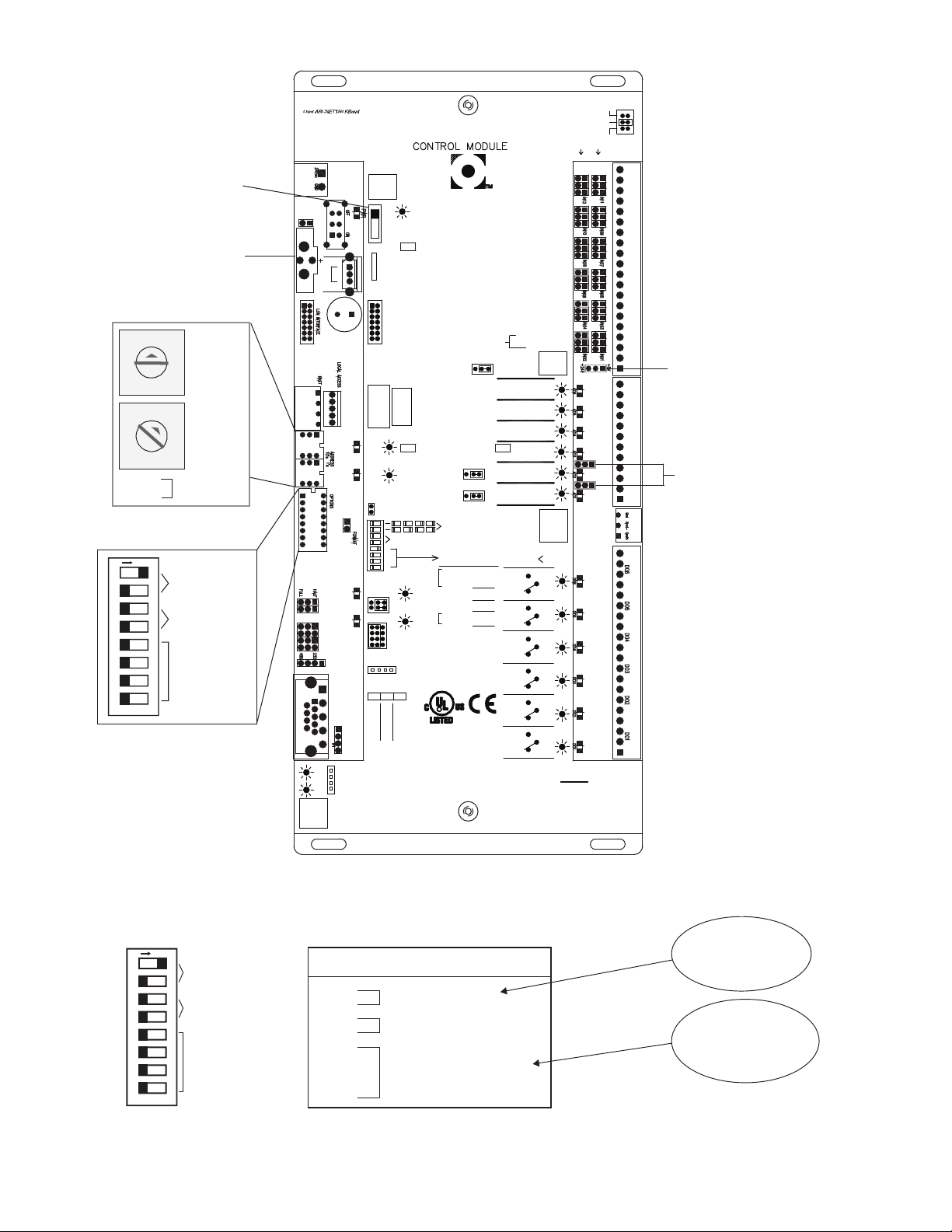
Pressure transducer input is factory installed in the
discharge line of compressor circuit 1. It is provided 5 vdc by
the unit main controller and returns a signal 1 to 5 vdc linearly.
The sensor’s range is 0 to 550 psig.
Water Valve(s) Control
Variable Building Waterflow Systems — Variable waterflow
configurations use only one water valve in the main water
supply pipe. The factory-installed valve is a normally open
motorized variable control type. The valve is controlled by a
2 to 10 vdc signal from the main unit controller using the
reverse/head pressure control output, which modulates to
maintain the head pressure set point.
Constant Building Waterflow Systems — Constant waterflow
configurations use two (2) water valves, only one of which is in
the main water supply pipe. The second valve is located in a
bypass pipe to the main outlet water pipe branched off of the
supply pipe immediately ahead of the first valve. This valve is
same type, but normally closed and is controlled in unison with
the first valve, but opposite position, such that the total opening
of the 2 valves always equals 100%.
VFD BYPASS (PCB1) — The variable frequency drive
(VFD) bypass option provides backup for the VFD in VAV
units. The bypass includes a control switch to select across-the-
line operation or operation through the VFD. When the bypass
is switched to across-the-line operation, the fan will not start
until the user indicates that the VFD access doors are secure via
the BACview keypad. The controller provides an output to sig-
nal the remote VAV dampers to open fully before the fan is
started at full speed. A duct high static (DHS) switch shuts
down the fan if the duct static exceeds the switch setting.
VENTILATION OUTPUT (PCB2) — The ventilation output
is a controller output signal (available for field connection) to a
field-supplied ventilation damper(s). This signal is activated
whenever the unit is in the occupied mode.
SPACE TEMPERATURE SENSOR (PCB2) — A field-sup-
plied Carrier space temperature sensor is required to maintain
space temperature in sensor mode.
SUPPLY AIR RESET — Supply air temperature set point
may be reset using one of several sensors. In the case of multi-
ple sensors and configurations, the precedence of sensor use is
from the top of the list to the bottom:
• EWT (PCB2) — EWT sensor installed, entering water
temperature reset configuration on
• SPT (PCB1) — Space reset configuration on
• MA_RA (PCB2) — Configured for return air sensing
EXHAUST FAN CONTROL OUTPUT (PCB1) — This out-
put is activated whenever the unit is in the occupied mode. This
is a 0 to10 vdc output that controls based on the building pres-
sure input set point.
CONDENSER WATER PUMP REQUEST (PCB2) — This
relay output (provided for field connection) is used to start/stop
the remote condenser water pump. This output is engaged
when the unit is in cooling mode and the supply fan is operat-
ing. This output is also engaged if the economizer freeze pro-
tection is activated.
WATER TOWER REQUEST (PCB2) — This relay output
(provided for field connection) is used to start/stop a remote
water cooling tower. This output is engaged when the unit is in
cooling mode and the supply fan is operating.
PHASE LOSS/REVERSAL PROTECTION SWITCH
(PCB2) — A phase loss/reversal switch may be installed to
detect over/under voltage conditions and phase loss or reversal.
This is a factory-installed option. This switch monitors the unit
power supply leads to detect phase loss or reversal. If the
switch detects improper phasing, an input is sent to the unit
controller, which shuts the unit down. When the switch opens,
the controller outputs are forced off, the alarm output will
close, the red alarm lamp will be lit on the BACview display,
and a system alarm will be generated. Unit reset is automatic
when the voltage and power phases have been restored.
FREEZE THERMOSTAT (FREEZ) (PCB2) — The economiz-
er freezestat, used in conjunction with an optional water

5
economizer coil or heating coil, is a factory-installed averag-
ing air temperature sensor positioned in the unit inlet airstream.
This may be either a thermistor sensor (automatic reset) or a
switch with capillary tube (manual reset). The unit activates
freeze protection when the sensed air temperature falls below
37 F. In freeze conditions, the supply fan will be stopped, all
compressors will stop, the economizer valve will open to
100%, the pump request output will remain on, and the alarm
lamp will light. This will maintain condenser water flow
through the coil to prevent freezing the coil while stopping all
other operations that could have contributed or will be affected
by the freeze condition. Unit reset is automatic when the con-
tacts on the freeze protection switch close again OR when the
thermistor sensed air temperature exceeds 42 F.
TOWER SUMP TEMPERATURE SENSOR (PCB2) —
This field sensor is used for monitoring (only) the tower sump
temperature.
LEAVING WATER TEMPERATURE SENSOR
(PCB2) — This sensor is used only for monitoring the leaving
water temperature.
BUILDING STATIC PRESSURE SENSOR (PCB1) —
This sensor is used to control the speed of the building exhaust
fan to maintain the building static pressure.
BUILDING EXHAUST FAN SPEED CONTROL
(PCB1) — This output controls building exhaust fan speed.
INDOOR AIR QUALITY (CO2) SENSOR (PCB1) — This
sensor monitors CO2levels and is used to provide demand ven-
tilation override with an air economizer.
OUTDOOR AIR TEMPERATURE SENSOR (PCB2) —
This sensor is used to monitor outdoor-air temperature. When
an air economizer is installed, this is used for changeover and
lockout.
INDOOR RELATIVE HUMIDITY SENSOR (PCB1) —
This sensor monitors the indoor relative humidity and controls
the humidity control relay.
HUMIDITY CONTROL RELAY (PCB2, DEHUMID-
IFY) — This relay controls a humidifier or dehumidification
device.
Wiring Control Devices — Standard controls for the
50XJ unit require no field wiring. Standard 50XJ controls in-
clude: supply-air temperature (SAT), duct static pressure
(DSP), duct high static limit switch (DHS), compressor status
relays (CRx), supply fan control (BPS_S and/or VFD), and
mixed-air/return-air sensor (MA_RA).
NOTE: The MA_RA sensor will be located in the return
airsteam if the unit does not have a water economizer, and in
the mixed airstream if the unit is equipped with a water
economizer.
EXTERNAL 0 TO 10 VOLT DC RESET SIGNAL (RESET,
PCB1) — This field-supplied 0 to 10 vdc signal is used to reset
the supply-air temperature. The controller will scale the signal
to provide 0 reset at 0 volts and 20 degrees of reset at 10 volts.
Wire the positive of the signal to controller terminal block J4,
terminal 16 and the negative to terminal 17.
SUPPLY AIR RESET BY SPACE TEMPERATURE — Use
a 10K-type II thermistor sensor installed at the entering water
temperature sensor location on PCB2 and configure the unit to
control reset by the entering water temperature sensor OR use
the normal space temperature sensor as described below. These
sensors may be connected in a series-parallel network in the
same manner as the space temperature sensor.
SPACE TEMPERATURE SENSOR (PCB1) — The space
temperature sensor (33ZCT55SPT) is used in the following
cases:
• When using the optional water economizer
• To determine the average temperature of the space
served
• To determine supply-air temperature reset, occupied
heating, unoccupied heating and cooling (refer to
Sequence of Operation in Operation section).
To wire the sensor, perform the following (see Fig. 1).
1. Identify which cable is for the sensor wiring.
2. Strip back the jacket from the cable for at least 3 inches.
Strip 1/4-in. of insulation from each conductor. Cut the
shield and drain wire from the sensor end of the cable.
3. Wire the sensor to controller terminal block J4, terminals
9 and 10. A typical 10K thermistor such as the
33ZCT55SPT sensor may be used. If the SPT sensor is
not installed and the MA_RA (mixed air/return air) sen-
sor is configured for return air, the 50XJ unit will use this
sensor to control supply air reset, occupied heat, and un-
occupied heating and cooling. See Fig. 2 for space tem-
perature sensor averaging.
HOT WATER OR STEAM VALVE (HWV, PCB1) — The
controller supplies a 0 to 10 vdc control signal for hot water or
steam valve control or electric heat control in occupied and un-
occupied heat modes. A field-installed step sequencer is re-
quired to convert this signal into 2, 4 or other stages of electric
heat. The positive signal is on terminal block J9, terminal 7,
with the signal common (negative) on terminal 8.
AIR TERMINALS AND FRESH AIR DAMPER
(PCB2) — The VAV terminal open (TRMOP), ventilation out-
put (VENTR), VAV terminal control (TRMCT), and heat inter-
lock relay (HIR) terminals provide dry contacts to command
the VAV terminals open; a ventilation damper open; VAV ter-
minals to control to their cooling set points; and VAV terminals
to control to their heat set points, respectively. These contacts
are located on terminal block J5: TRMOP terminals 7 and 8,
VENTR terminals 5 and 6, TRMCT terminals 3 and 4, and
HIR terminals 1 and 2.
REMOTE OCCUPANCY (PCB1) — The unit may be com-
manded by a remote control system or a twist timer to become
occupied and run when a set of dry contacts close. To enable
remote occupancy control, configure the occupancy point in
BACview to "remote (DI) on/off" and wire the remote contacts
to terminal block J4, terminals 17 and 18.
2345 61
SW1
SEN
BRN (GND)
BLU (SPT)
RED(+)
WHT(GND)
BLK(-) CCN COM
SENSOR WIRING
Fig. 1 — Space Temperature Sensor
Typical Wiring (33ZCT55SPT)
a33-675ef

6
SMOKE DETECTOR/FIRE ALARM SHUTDOWN (FSD)
(PCB1) — To allow a smoke detector to shut the unit down,
remove the jumper from terminal block J4, terminals 19 and 20
and wire these terminals to a set of normally closed contacts on
the smoke detector.
ALARM (ALARM) OUTPUT (PCB1) — A Form C dry
contact is provided to signal when the controller has an active
alarm. To use these for remote annunciation, connect wiring to
terminal block J10, terminal 18 (normally open), terminal 17
(common), and/or terminal 16 (normally closed).
J4
9
10
RED
BLK
RED RED
BLK BLK
BLK
RED
BLK
RED
SENSOR 1 SENSOR 2 SENSOR 3SENSOR 4
J4
9
10
RED
BLK
RED
BLK
SENSOR 2
SENSOR 1
RED
RED
BLK
SENSOR 3
SENSOR 4
BLK
BLK
RED
RED RED
BLK BLK
SENSOR 8SENSOR 9
SENSOR 5
RED
BLK
SENSOR 6
SENSOR 7
BLK
RED
SPACE TEMPERATURE AVERAGING — 4 SENSOR APPLICATION
SPACE TEMPERATURE AVERAGING — 9 SENSOR APPLICATION
Fig. 2 — Space Temperature Averaging
LEGEND
Field Wiring
a50-8742
a50-8743

7
CONTROL AND DISPLAY
Controller — The microprocessor-based controller pro-
vides complete system control of unit operation. See Fig. 3 for
typical controller components. The controller monitors all sys-
tem sensors and makes operating decisions based upon the us-
er's configuration inputs. See Fig. 4.
A scheduling function, programmed by the user, controls
the occupied/unoccupied schedule. Up to 4 daily schedules, 12
holiday schedules, and 2 override schedules may be
programmed.
Local access to the microprocessor control may be accom-
plished via the BACview keypad/display unit (BV6H). See
Fig. 3. Recommended application is one BACview display per
jobsite.
The microprocessor control is capable of operating in a
stand-alone control mode and also supports communications
with BACnet, Modbus, and optionally LonWorks building au-
tomation protocols.
In addition, the microprocessor control has the following
features:
• simple access to set points, time schedules, status values,
and unit configuration parameters
• alarm conditions are indicated via an alarm LED (light-
emitting diode) and/or an audible signal
• password protection
• compressor minimum off time (5 minutes) feature
• service diagnostic mode
• field-installed room temperature sensor
• an on/off switch that may be used to cycle the controller
• a battery to maintain time and date in the event of a power
outage (do not remove the battery when power is off)
• DIP switches to configure communication baud rate and
protocol
The IO Flex 6126 controller has 6 binary outputs, 12 uni-
versal inputs and 6 analog outputs. Binary outputs have N/O
(normally open) and N/C (normally closed) contacts used to
turn components on or off. The universal inputs are used to
monitor input from various sensors. These universal inputs can
be set for one of three different sensor input types:
1. Voltage,
2. Temperature (thermistor) or discrete contact, or
3. Current.
There are 2 columns of jumpers to the left of the universal
input plugs, see Fig. 4. The jumpers are used to configure the
input to the desired type (voltage, temperature, etc.). The left
row of jumpers are for the even numbered universal inputs, UI-
12 thru UI-2 (top to bottom). The right column of jumpers are
for the odd numbered universal inputs, UI-11 thru UI-1 (top to
bottom). When the jumper is in the center position (default set-
ting) the universal input is configured for temperature and dis-
crete contact (digital input), such as duct high-limit switch.
When the jumper is in the top position, the input is configured
for a voltage input, for example, a humidity sensor. The bottom
jumper position is used for milliamp input.
The following settings are made at the factory, see Fig. 5:
1. Auxiliary Power Output (Aux Pwr Out) jumper should be
set on 24V to power the 0 to 10 vdc sensors.
2. Analog outputs (AO) labeled AO-1 and AO-2 should be
set on Volts.
3. The module address (MAC) rotary switches are set for
'01' from the factory. The MAC may be reconfigured in
the field if required.
NOTE: To download software to the I/O Flex 6126, the
MAC setting must be on '01'.
Example: If the control module’s address is 01, point the
arrow on the tens (10’s) switch to 0 and the arrow on the
ones (1’s) switch to 1. See Fig. 4.
NOTE: The I/O Flex 6126 recognizes its address only af-
ter power has been cycled.
The communication rate is factory-configured for 38.4 baud
rate.
Aux
+
Gnd
Aux Pwr Out
+5V
+24V
2
1
+
4
3
5
6
7
8
9
10
11
12
13
14
15
16
17
18
19
20
UI-01
+
Gnd
+
Gnd
+
+
Gnd
+
+
Gnd
+
+
Gnd
+
+
Gnd
+
UI-02
UI-03
UI-04
UI-05
UI-06
UI-07
UI-08
UI-09
UI-10
UI-11
UI-12
AO-2
AO-3
AO-4
AO-1Gnd
+
+
3
1
2
7+
Gnd
Gnd
+
6
4
5
Gnd 8
9+
Gnd
AO-5 10
Gnd
AO-6 12
11+
Gnd
Xnet -
Xnet +
Xnet
Remote
Expansion
2
BO-1
1
9
BO-3
BO-2
4
5
3
BO-4
6
7
8
BO-5
BO-6
12
11
10
13
14
16
15
18
17
I
/
O
Flex 6126
Pwr Out
AO Mode Select
10V
20mA
20mA 10V
BACnet®Universal
Mode
RTD
0-10V
0-20mA
Power
Off
24VAC
Gnd
Batt
CR2032
-
+
Port 2b*
Gnd
Rnet +
Rnet -
+12V
Rnet
+12V
Rnet
Rnet-
Gnd
Rnet+
Sense
Local
Access
Run
Error
Rx
Tx
Module
10's
9600
76.8k
19.2k
38.4k
Baud
Full Half
Duplex
BT485
BT485
Net + Port 1
Gnd
Net -
Tx
Rx
CAUTION:
To Reduce The Risk of Fire
Interconnect the Outputs of
Different Class 2 Circuits.
or Electric Shock, Do Not
BO Rating 5A @ 250VAC
Class 2
24VAC, 50-60 Hz
20VA, 0.83A
Use Copper
Conductors Only
232
EIA- EIA-
485
Port 1
Port 2a
Therm
Dry
Unused
5
6
7
8
Network Switches
(0 = off, 1 = on)
MSTP (m)
MSTP (s)
PTP
SLTA
*PlugIn
*Ethernet
8 7 6 5
Protocol
0000
0001
0010
0011
0100
1101
1110
1111
BACnet
N2
Modbus
LON
®
®
®
®
Port 2a
2w 4w
Tx+
n/c
n/c
Net+
Rx+
Rx-
Tx-Net-
232
Tx
DTR
DCD
Rx
Signal Ground
Address
1's
On
Pulse Count Ability
Input
Select
Rate
Format
Made in USA
ARC156
Only
26VDC, 0.17A, 4W
Management Equipment
TYPE: 002108
Open Energy
R
88FO
E143900
19
20
Unused
Even Odd
POWER 24 VAC
BACVIEW6
(RS) ROOM
SENSOR
UNIVERSAL
INPUTS
ANALOG
OUTPUTS
BINARY
OUTPUTS
MENU: <ALARM>UNOCCUPIED
OAT:000.0°.000:TALF0°F
SHUTDOWN:[Off] 100% OA STD PROGRAM”
[ OK ][ CANCEL ][ DECR ][ INCR ]
1 2 34 5 MUTE FN
6 7 89 0 • ENTER
BACview6
Fig. 3 — Typical Controller Components
a62-608

8
Aux
+
Gnd
Aux Pwr Out
+5V
+24V
2
1
+
4
3
5
6
7
8
9
10
11
12
13
14
15
16
17
18
19
20
UI-01
+
Gnd
+
Gnd
+
+
Gnd
+
+
Gnd
+
+
Gnd
+
+
Gnd
+
UI-02
UI-03
UI-04
UI-05
UI-06
UI-07
UI-08
UI-09
UI-10
UI-11
UI-12
AO-2
AO-3
AO-4
AO-1Gnd
+
+
3
1
2
7+
Gnd
Gnd
+
6
4
5
Gnd 8
9+
Gnd
AO-5 10
Gnd
AO-6 12
11+
Gnd
Xnet -
Xnet +
Xnet
Remote
Expansion
2
BO-1
1
9
BO-3
BO-2
4
5
3
BO-4
6
7
8
BO-5
BO-6
12
11
10
13
14
16
15
18
17
I
/
O
Flex 6126
Pwr Out
AO Mode Select
10V
20mA
20mA 10V
BACnet®Universal
Mode
RTD
0-10V
0-20mA
Power
Off
24VAC
Gnd
Batt
CR2032
-
+
Port 2b*
Gnd
Rnet +
Rnet -
+12V
Rnet
+12V
Rnet
Rnet-
Gnd
Rnet+
Sense
Local
Access
Run
Error
Rx
Tx
Module
10's
9600
76.8k
19.2k
38.4k
Baud
Full Half
Duplex
BT485
BT485
Net + Port 1
Gnd
Net -
Tx
Rx
CAUTION:
To Reduce The Risk of Fire
Interconnect the Outputs of
Different Class 2 Circuits.
or Electric Shock, Do Not
BO Rating 5A @ 250VAC
Class 2
24VAC, 50-60 Hz
20VA, 0.83A
Use Copper
Conductors Only
232
EIA- EIA-
485
Port 1
Port 2a
Therm
Dry
Unused
5
6
7
8
Network Switches
(0 = off, 1 = on)
MSTP (m)
MSTP (s)
PTP
SLTA
*PlugIn
*Ethernet
8 7 6 5
Protocol
0000
0001
0010
0011
0100
1101
1110
1111
BACnet
N2
Modbus
LON
®
®
®
®
Port 2a
2w 4w
Tx+
n/c
n/c
Net+
Rx+
Rx-
Tx-Net-
232
Tx
DTR
DCD
Rx
Signal Ground
Address
1's
On
Pulse Count Ability
Input
Select
Rate
Format
Made in USA
ARC156
Only
26VDC, 0.17A, 4W
Management Equipment
TYPE: 002108
Open Energy
R
88FO
E143900
19
20
Unused
Even Odd
Aux Pwr Out +24V
AO Mode Select - Volts
Power Switch
Battery
10's
1's
1
3
4
5
2
7
8
9
6
0
1
3
4
5
2
7
8
9
6
0
O
N
1 2 34 5 6 7 8
SET TO 38.4 BAUD
UNUSED
MSTP (m)
Module Address
Options
10’S=0
1’S=1
MODULE
ADDRESS
a62-606
Fig. 4 — Control Module
Factory values:
SWITCHESPOSITION
1=1
2=0
3=0
4=0
5=0
6=0
7=0
8=0
BAUD RATE: 38.4
UNUSED
NETWORK PROTOCOL:
MSTP(m) BACnet
OFF = 0 ON = 1
SET TO 38.4k BAUD
UNUSED
MSTP(m)
O
N
1 2 34 5 6 7 8
4 BAUD RATES
8NETWORK
PROTOCOLS
a62-576
Fig. 5 — Control Module Switch Positions

9
BACview Interface Device — The BACview keypad/
display features a numeric keypad, direction keys, four func-
tion keys, and a backlit LCD (liquid crystal diode) display. See
Fig. 6. For specifications on BACview display see Table 2. The
display is a large 4-line by 40-character display that is easy to
read, even in low light conditions. The keypad/display has a
padded backing and plugs directly into the controller using at-
tached cable. See Fig. 6. To adjust the contrast of the display,
turn the contrast screw on top of the BACview clockwise to
lighten the display or counterclockwise to darken it. See Fig. 6.
The BACview screen goes dim after 10 minutes of inactivi-
ty. Press any key except MUTE or FN to activate the screen.
The user can change the length of inactivity on the KEYPAD
screen.
Table 2 — BACview Specifications
Log On to BACview Display — It is not necessary
to log onto the BACview display to view the unit status, com-
ponent run times, etc. The user must log onto the display to
change any set points or configuration values. If the user at-
tempts to open a screen that requires a login and they have not
already logged onto BACview, the LOGIN screen will appear.
This logon follows the same process described below.
There are two logons for the BACview: Admin and User.
Logging in at the User level allows all set points and schedul-
ing to be changed, but a User cannot change either the User or
Admin passwords or the unit configuration. The Admin logon
allows all the functionality of a User, but adds the ability to
change the User password, ability to change the router data and
BACnet parameters, change the factory configuration, calibrate
sensors, and initiate the unit self-test.
To log on to the BACview, perform the following proce-
dure:
1. If the standby screen is visible, press any key to switch
to the HOME menu.
2. If another screen is displayed, and there is no [LOGIN]
softkey displayed, press the [HOME] softkey to switch to
the HOME menu.
3. Press the [LOGIN] softkey.
4. The following prompt is displayed:
5. Use the numeric keys to enter the User or Admin pass-
word and then press <ENTER> or [OK].
NOTE: The default Admin password is 1111.
6. If an invalid password is entered, the warning "horn" will
chirp. After three failed login attempts the display
switches back the screen where the [LOGIN] softkey was
pressed.
Log Out of BACview Display — The system will
automatically log the User or Admin out of the BACview dis-
play if no display key is pressed for 10 minutes. The inactivity
timer can be adjusted through the "Keypad" screen.
1. If the standby screen is visible, press any key to switch
to the HOME menu.
2. If another screen is displayed, press the [HOME] to
switch to the HOME menu.
3. Press the [LOGOUT] softkey to force the system to log
the user out. The text adjacent to the [LOGOUT] softkey
changes to "LOGIN" when the user is logged out.
Change Default User Password — The user must
log on to the BACview Display as ADMIN to change the user
level password. Alternately, both USER and ADMIN pass-
words may be changed via network tools.
1. If the standby screen is visible, press any key to switch
to the HOME menu.
2. If another screen is displayed, press the [HOME] to
switch to the HOME menu.
3. Press the <right arrow> to scroll down through the
HOME menu options. Move the cursor (brackets) over
[UserPW], then press <ENTER>.
4. The following prompt is displayed:
5. The current user password is shown. Enter the new User
password and then press <ENTER>, OR press [PREV] to
leave the current password intact.
Automatic Self-Test — The controls are programmed
with several automatic run tests that check connection and op-
eration of major components. To perform the run test, verify
that the alarm lamp is off. The red alarm lamp will light during
the run tests and the run tests will cease if other alarms become
active. Once an automatic test is started, the unit will remain in
self-test mode for four minutes after all automatic run tests
complete.
There are separate tests for each section of the unit: variable
volume fan, bypass or constant volume fan, compressor cool-
ing, heating, and water economizer.
To perform a self-test:
Turn unit power on.
1. Log on to the BACview display as ADMIN.
2. From the HOME menu, press the [CONFIG] softkey.
3. From CONFIGURATION menu, press [FACTORY]
softkey.
4. From the FACTORY CONFIGURATION menu, press
the [FACT TEST] softkey.
5. Press the <up arrow> or <down arrow> to select the test
to run, then press <ENTER>.
6. Press the [INCR] softkey to initiate the test, then press
<ENTER>. The test will start 2 seconds later.
The test will automatically end when the test sequence is
complete. To manually halt a test, move the brackets to the test
to stop and press <ENTER>. Press the [INCR] softkey to select
Off, then press <ENTER>.
FEATURE SPECIFICATION
Power Supplied by the Rnet port througt the cable
(+12 vdc at 250 mA)
Display
4-line by 40-character backlit LCD display,
alarm LED and audible horn for alarm
conditions
Protection 15 KV ESD protection to the enclosure.
Physical Rugged aluminum enclosure for protection
Environmental
Operating Range
32-120 F (0-48.9 C)
10-90% RH non-condensing
Overall
Dimensions
Width: 9 5/8 in. (24.5 cm)
Height: 4 15/16 in. (12.5 cm)
Weight 1.5 lb (0.68 kg)
Listings UL-916 (PAZX), CE (1997), FCC Part 15-Sub-
part B-Class A
Admin or User
Password: [ ]
View/Set User
Password: [ ]

10
GENERAL TEST INFORMATION — The self-test routine
requires the user to login with Admin access.
The self-test routines will NOT operate if there is an active
alarm. If the user attempts to start a test with an alarm, the point
will automatically switch from On to Off.
During the testing, the BACview alarm lamp will be on and
the fans, compressors, and heating should halt operation, ex-
cept during the applicable tests.
The self-test routines will halt if there is an active alarm.
The self-test routines will lock the unit into test mode for 4
minutes after the last test has completed.
At test start-up and at each test step, the alarm output relay
will turn on for 2 seconds. The relay status is indicated by a red
LED adjacent to the output.
VARIABLE VOLUME FAN TEST SEQUENCE (VAV
UNITS ONLY) — The VAV fan test cannot be conducted
while running the compressor start/stop test.
1. As the alarm relay closes, the supply fan should start
and ramp up to 20% speed.
2. Thirty seconds after the test starts, the supply fan should
ramp up to 35% speed.
3. After 60 seconds the test point should be off and the fan
should stop.
CONSTANT VOLUME FAN TEST SEQUENCE (Non-
VAV Units Only) — The airflow type (base configuration
screen) should be set to constant. This test cannot be conducted
while running the compressor start/stop test. This is the same
test point used to test the VFD bypass.
Since constant volume units do not have remote VAV termi-
nals, there is no built-in delay to allow remote boxes to open
before starting the fan.
1. As the alarm relay closes, the supply fan should start at
full speed.
2. After 5 seconds the test point should be off and the fan
should stop.
VFD BYPASS TEST (VAV Units Only) — The airflow type
(base configuration screen) should be set to variable. This test
cannot be conducted while running the compressor start/stop
test test.
The VFD bypass control switch must be set to line (bypass)
mode.
The access panel secure (Access Panel SC) on the CNTL
CONFIG screen must be set to yes to allow this test to operate.
1. As the alarm relay closes, the TRMOP output engages
to signal the remote boxes to open.
2. Thirty econds after the test starts, the supply fan should
start at full speed.
3. After 60 seconds the test point should be off and the fan
should stop.
COMPRESSOR START/STOP TEST — This test operates
each compressor, individually, for 5 seconds. If a compressor
fault is detected for two continuous seconds, this test should
terminate.
Rnet
Local
Access
MENU: <ALARM>UNOCCUPIED
OAT:000.0°F LAT:000.0 °F
SHUTDOWN:[Off] 100% OA STD PROGRAM”
[ OK ][ CANCEL ][ DECR ][ INCR ]
BACview6
CONTRAST
SCREW
HOTKEYS ARROW KEYS
SELECTED
CHARACTER IS
UNDERLINED
SOFTKEY LABEL
SOFTKEY
HIGHLIGHTED
FIELD IN
BRACKETS
1 2 34 5 MUTE FN
6 7 89 0 • ENTER
Fig. 6 — BACview Connection to Unit Controller
a62-573

11
This test will operate the number of compressors indicated
on the "# of Comps" section of the BASE CONFIG screen.
1. As the alarm relay closes, Compressor 1 starts and
operates for 5 seconds.
2. One second after compressor 1 stops, compressor 2 starts
and operates for 5 seconds.
3. One second after compressor 2 stops, compressor 3 (if
configured) starts and operates for 5 seconds.
4. One second after compressor 3 stops, compressor 4 (if
configured) starts and operates for 5 seconds.
5. After the last configured compressor stops, the test point
returns to off.
HEATING — This test operates the analog output used to con-
trol a field-installed heating valve. The timing is set to allow
the use of a DC voltmeter to check the controller output.
This test will NOT test electric heat. If the heat type indicat-
ed on the "Heat Config" section of the BASE CONFIG screen
is set to "electric" this test will not run.
1. As the alarm relay closes, the heating output will be
0 vdc.
2. Ten seconds later the heating output moves to 5 vdc.
3. Ten seconds later the heating output moves to 10 vdc.
4. Ten seconds later the test point returns to Off and the heat
output returns to normal control.
WATER ECONOMIZER (H2O ECON) — This test checks
operation of the modulating valve (MVLV) and economizer
valve (ECONO).
1. As the alarm relay closes, the output to both valves is
0 vdc. Both valves should close.
2. Two minutes later, economizer valve opens (10 vdc) and
modulating valve remains closed (0 vdc).
3. Two minutes later, economizer valve closes (0 vdc) and
modulating valve opens (10 vdc)
4. Two minutes later the test point returns to off and the
valves return to normal control.
Set the Clock — The user must be logged on as either a
User or Admin to set the clock. To set the clock, perform the
following procedure:
1. From the HOME menu, press the arrow keys until the
cursor brackets are around ClockSet, then press
<ENTER>.
2. Use the arrow keys to scroll around the screen and select
the data fields to change.
3. To change a field, move the cursor (brackets) to the de-
sired field then press enter.
4. If the wrong field is entered or you do not want to change
a value, press [CANCEL] to leave the current setting in-
tact.
5. To setup Daylight Savings time and Standard time, move
the cursor (brackets) over DST and then press <EN-
TER>. You can then scroll through and set the time of
day to start daylight savings mode (default is 02:00), the
amount of time to offset (default is 60 minutes), begin-
ning (B) and ending (D) dates.
Configure Schedules — Local schedules are one
method of starting and stopping the unit at specified intervals.
There are four normal schedules that provide day to day opera-
tion. There are twelve holiday schedules that are used to over-
ride the normal schedule and set the unit to unoccupied mode.
There are two override schedules that are used to override the
normal and holiday schedules to force the unit into occupied
mode.
The user must be logged on as User or Admin to configure
the schedules using following procedure.
NORMAL (LOCAL) SCHEDULES
1. From the HOME menu, select the the [CONFIG] soft-
key to enter the CONFIGURATION menu.
2. Use the arrow keys to select OCCUPANCY, then press
<ENTER>.
3. Press the [LOCAL] softkey to adjust the normal sched-
ules.
4. Use arrow keys to scroll around the screen and select the
data field to change. These buttons scroll through the data
fields, as well as up and down the screen.
5. To change a field, move the cursor brackets to the desired
field then press <ENTER>.
6. If the wrong field is entered or you do not want to change
a value, press [CANCEL] to leave the current setting in-
tact.
7. Press the [PREV] softkey to move the previous screen or
schedule. Press the [NEXT] softkey to move to the next
schedule screen.
If viewed as a single large screen, the layout is dis-
played as follows:
The time settings are in 24-hour time. The Start Time line is
used to set the occupied start time. The End Time line is used to
set the unoccupied start time. The “Apply Times Above to”
section is used to set whether the schedule is active each day of
the week. Select Yes to activate the schedule on a given day of
the week and No to ignore the schedule on that day. The NEXT
item at the bottom of screen moves you to the next normal
schedule set point.
Setting the start time and end time to 0 hours and 0 minutes
disables a schedule.
HOLIDAY SCHEDULES
1. From the HOME menu, select the [CONFIG] softkey
to enter the CONFIGURATION menu.
2. Use the arrow keys to select OCCUPANCY, then press
<ENTER>.
3. Press the [HOLIDAY] softkey to adjust the holiday
schedules.
4. Use arrow keys to scroll around the screen and select the
data field to change. These buttons scroll through the data
fields, as well as up and down the screen.
5. To change a field, move the cursor brackets to the desired
field then press <ENTER>.
6. If the wrong field is entered or you do not want to change
a value, press [CANCEL] to leave the current setting in-
tact.
7. Press the [PREV] softkey to move the previous screen or
schedule. Press the [NEXT] softkey to move to the next
schedule screen.
--------------------- Schedule #1 ---------------------
Start Time [hh:mm] 0: 0
End Time [hh:mm] 0: 0
Apply Times Above to
Mo
nTue Wed Thu Fri Sat Sun
No No No No No No No
[->PREV] [->NEXT] [->HOME]

12
If viewed as a single large screen, the layout is as follows:
The Month and Day entries select the month (1 to 12) and
day (1 to 31) of the holiday. The time settings are in 24-hour
time, with Start Time used to set the time of day to start of the
holiday. The End Time line is used to set the end of the holiday.
The NEXT item at the bottom of screen moves you to the next
holiday schedule set point.
Setting the month or day or start time and end time to 0 dis-
ables the holiday schedule.
The holiday schedule cancels any normal schedule set for
the holiday date and time. If a normal schedule is set from 0700
to 1800 hours and a holiday schedule is set for the same day
from 0800 to 1700, the unit will be unoccupied from midnight
to 0700. The unit will change to occupied mode at 0700 until
0800. At 0800 the holiday schedule forces the unit to
unoccupied mode until 1700. At 1700, control returns to the
normal schedule and the unit goes occupied from 1700 to
1800. At 1800, the unit returns to unoccupied mode per the
normal schedule.
OVERRIDE SCHEDULES
1. From the HOME menu, select the [CONFIG] softkey
to enter the CONFIGURATION menu.
2. Use the arrow keys to select OCCUPANCY, then press
<ENTER>.
3. Press the [OVERRIDE] softkey to adjust the override
schedules.
4. Use arrow keys to scroll around the screen and select the
data field to change. These buttons scroll through the data
fields, as well as up and down the screen.
5. To change a field, move the cursor brackets to the desired
field then press <ENTER>.
6. If the wrong field is entered or you do not want to change
a value, press [CANCEL] to leave the current setting in-
tact.
7. Press the [PREV] softkey to move the previous screen or
schedule. Press the [NEXT] softkey to move to the next
schedule screen.
If viewed as a single large screen, the layout is as follows:
The Month and Day entries select the month (1 to 12) and
day (1 to 31) of the override. The time settings are in 24-hour
time, with Start Time used to set the time of day to start of the
override. The End Time line is used to set the end of the over-
ride. The NEXT item at the bottom of screen moves you to the
next override schedule set point.
Setting the month or day or start time and end time to 0 dis-
ables the override schedule.
The override schedule has the highest priority of any sched-
ule. When an override schedule is active, it overrides any nor-
mal or holiday schedule and forces the unit to occupied mode.
In the example listed under the holiday schedule, assume an
override schedule is set for 1300 to 1400 of that day. The unit
operation remains the same, except the unit will switch to oc-
cupied mode from 1300 to 1400.
Adjust Set Points — The user must be logged on as
User or Admin to configure set points.
1. From the HOME menu, select the [CONFIG] softkey
to enter the CONFIGURATION menu.
2. Use the arrow keys to select SETPOINT, then press
<ENTER>.
3. Use arrow keys to scroll around the screen and select the
data field to change. These buttons scroll through the data
fields, as well as up and down the screen.
4. To change a field, move the cursor brackets to the desired
field then press <ENTER>.
5. If the wrong field is entered or you do not want to change
a value, press [CANCEL] to leave the current setting
intact.
See Table 3 for a description of the items on the SETPOINT
menu.
Table 3 — Setpoint Menu
LEGEND
--------------------- Holiday Schedule #1 ---------------------
Mont
h:0
Day : 0
Start Time [hh:mm] 0: 0
End Time [hh:mm] 0: 0
[->PREV] [->NEXT] [->HOME]
--------------------- Override Schedule #1 ---------------------
Mont
h:0
Day : 0
Start Time [hh:mm] 0: 0
End Time [hh:mm] 0: 0
[->PREV] [->NEXT] [->HOME]
SET POINT DEFAULT RANGE
Duct Static Pressure (VAV Setpoint) 1.5 in. wg 0.05 to 3 in. wg
Supply Fan Proof Level (Fan On) 0.4 in. wg 0 to 0.5 in. wg
Occupied Cooling (Space) 74 F (Occupied Heating +1) to
100 F
Occupied Heating (Space) 70 F 0 to (Occupied Cooling -
1) F
Unoccupied Cooling (Space) 85 F (Unoccupied Heating +1)
to 100 F
Unoccupied Heating (Space) 55 F 0 to (Unoccupied Cool-
ing -1) F
Supply Air Cooling 55 F 50 to 70 F
Supply Air Heating 120 F (Cooling Set point + 10)
to 140 F
Supply Air Reset Ratio 3.0 F 1 to 10 F
Maximum Supply Air Reset 20 F 0 to 20 F
Refrig. Head Pressure 225 psig 200 to 300 psig
Economizer Lockout (Air Econ) 68 F 50 to 85 F
Air Econ Minimum Position 20% 0 to 100%
Indoor Air Quality 850 ppm 0 to 2000 ppm
Occupied Humidify 0% rh 0 to Occupied Dehumid-
ify % rh
Occupied Dehumidify 100% rh Occupied Humidify to
100% rh
Unoccupied Humidify 0% rh 0 to Unoccupied Dehu-
midify% rh
Unoccupied Dehumidify 100% rh Unoccupied Humidify to
100% rh
Space Static Pressure 0.02 in. wg 0 to 0.3 in. wg
Space Static Sensor-Low -0.5 in. wg -1 to -0.2 in. wg
Space Static Sensor-RNG (range) 1 in. wg 0 to 2 in. wg
H2O Econ Flush Duration 12 min 3 to 20 minutes
H2O Econ Flush Interval 12 hrs 12 to 168 hours
T55 Time Override Hours 1 hour 0 to 24 hours
ppm — Parts Per Million
rh — Relative Humidity
VAV — Variable Air Volume

13
Configure Basic Unit — The user must be logged on
as Admin to adjust these control configurations.
1. From the HOME menu, select the press the [CONFIG]
softkey to enter the CONFIGURATION menu.
2. From the CONFIGURATION menu, press the [FACTO-
RY] softkey to enter the FACTORY CONFIGURATION
menu.
3. Use arrow keys to scroll around the screen and select the
data field to change. These buttons scroll through the data
fields, as well as up and down the screen.
4. To change a field, move the cursor brackets to the desired
field then press <ENTER>.
5. If the wrong field is entered or you do not want to change
a value, press [CANCEL] to leave the current setting in-
tact.
See Table 4 for a description of the items on the FACTORY
CONFIGURATION menu.
Table 4 — Factory Configuration Menu
*These points are factory set to the appropriate value if affected by a factory-
installed option.
Unit Configuration — The user must be logged on as
Admin or User to adjust these configuration points.
1. From the HOME menu, select the press the [CONFIG]
softkey to enter the CONFIGURATION menu.
2. From the CONFIGURATION menu, press the [UNIT]
softkey to enter the second CONFIGURATION menu.
3. Use arrow keys to scroll around the screen and select the
data field to change. These buttons scroll through the data
fields, as well as up and down the screen.
4. To change a field, move the cursor brackets to the desired
field then press <ENTER>.
5. If the wrong field is entered, do not change a value, press
[CANCEL] to leave the current setting intact.
See Table 5 for a description of the items on the CONFIGU-
RATION menu.
Table 5 — Configuration Menu
*These points are factory set to the appropriate value if affected by a factory-
installed option.
Unit Status — The system status can be monitored with-
out logging onto the BACview display by pressing the [Status]
softkey on the HOME menu and using the arrow keys to navi-
gate the screen.
See Table 6 for a description of the items on the on the
UNIT STATUS menu.
Display / Set Runtime Alarms — It is not necessary
to log onto the BACview display to view the compressor and
fan run time values. It is necessary to log onto BACview to set
runtime limits or clear the accumulated run times.
To view run times, press the [CONFIG] softkey on the
HOME menu, then select the RUNTIME option from the
CONFIGURATION menu. Use the arrow keys to scroll
through the display.
To change runtime alarm values move to the column
marked "Alarm" and press <ENTER> then use the numeric
keys to enter the alarm value and again press <ENTER>. To re-
set the accumulated run time, move to the column marked
"Clear", press <ENTER>, then the [INCR] softkey to select
"Yes", then press <ENTER>. The display will prompt for the
user or admin passwords if the operator is not already logged
on to the display.
Display Alarms and Alarm History — It is not
necessary to log onto the BACview to display the Current
Alarms or the Alarm History. To view the Alarm information,
press the [ALARM] softkey on the HOME menu.
POINT NAME DEFAULT OPTIONS
Occupancy Input Selection Remote DI
Always Occupied
Local Schedule
BACnet Schedule
BAS On/Off
Remote DI
Airflow Type Variable* Constant or Variable
Number of Compressors 4* 2, 3, or 4
Heat Type None* None, Hydronic, Electric
Econ Water Flow Type Constant* Constant or Variable
Mixed/Return Sensor Type None* None, Mixed or Return
Water Econ Freeze Sensor
Ty p e None* None, Thermistor, or Switch
Entering Water Temp Sensor None* None or Installed
(Condenser) Water Flow
Switch None* None or Installed
Modulating Water Valve None* None or Installed
Head Pressure Control None* None or Enabled
POINT NAME DEFAULT OPTIONS
Occupancy Input Selection Remote DI
Always Occupied
Local Schedule
BACnet Schedule
BAS On/Off
Remote DI
VFD Access Panel Secure No No or Yes
Heat Type None*
None
Hydronic
Electric
Occupied Heating Allowed Yes No or Yes
Allow Unoccupied Free Cooling No No or Yes
Allow Mechanical Dehumidification No No or Yes
Supply Air Reset by EWT (Entering
Water Temperature) No No or Yes
Supply Air Reset by SPT (Space
Temperature) No No or Yes
Water Econ Flush Type Timed Timed or Daily
Air-Side Economizer Installed None None or Installed
Outdoor Air Temp Sensor None None or Installed
Indoor Air Quality Sensor None None or Installed
Indoor Relative Humidity None None or Installed
Air-Econ Enthalpy Control No No or Yes
Space Static Pressure Control No No or Yes
Technician - Area Code 000 3-digit number
Technician - Prefix 000 3-digit number
Technician - Extension 0000 4-digit number

14
Table 6 — Unit Status Menu
Set Controller Address — The UC Open XP control-
ler’s rotary switches determine the UC open XP’s MAC ad-
dress when it is placed on a BACnet MS/TP network. The rota-
ry switches define the MAC address portion of the device’s
BACnet address, which is composed of the network address
and MAC address.
Perform the following procedure to assign an address:
1. Turn off the UPC Open XP power switch.
2. Using the rotary switches, set the controller address. Set
the Tens (10’s) switch to the tens digit of the address, and
set the Ones (1’s) switch to the ones digit. For example, if
the controller address is 25, point the arrow on the 10’s
switch to 2 and the aroow on the 1’s switch to 5. See Fig.
7.
3. Turn on the UPC Open XP power switch. The controller
reads the address each time power is applied.
50XJ Variable Frequency Drive (VFD) Control
and Start-Up — The VFD is factory-wired and pro-
grammed for proper operation with the unit controls. No instal-
lation or service adjustments are normally required. There is a
keypad/display mounted on the front of the VFD which is inde-
pendent of the main 50XJ control display.
For basic information on using the VFD keypad/display re-
fer to the VFD Control and Display section.
VFD START-UP PROCEDURE — The following procedure
is used to start up the VFD.
1. Switch the 50XJ PCB1 power switch to OFF.
2. Apply VFD unit power. From the VFD keypad, perform
the following steps.
3. Press [EXIT] at the "Auto Choice - Is this an air-handler
or rooftop?" prompt.
4. Press [MENU] until the "Main Menu" is displayed.
5. Use the UP/DOWN keys to select "ASSISTANTS" and
press <ENTER>.
6. Use the UP/DOWN keys to select "Commission Drive"
and press [SEL].
7. Verify the following parameters. If they are correct, press
<SAVE> to move to the next parameter. Use the UP/
DOWN keys to change parameters, then press <SAVE>.
If you make a mistake in the data entry, press <EXIT>
and re-start the procedure at Step 6.
9905 Motor Nom Volt - should equal unit voltage
(230V or 460V)
9906 Motor Nom Current - equal to motor FLA (see
motor nameplate).
9907 Motor Nom Freq - always 60 Hz.
9908 Motor Nom Speed - set to motor nameplate
RPM.
9909 Motor Nom Power - set to motor nameplate HP.
9902 HVAC Default - press <EXIT>
8. Press <EXIT>, <EXIT>.
9. Press [MENU] until the "Main Menu" is displayed.
10. Use the UP/DOWN keys to select "PARAMETERS" and
press <ENTER>.
STATUS POINT INDICATORS
Operating Mode
OFF
Fan Only
Economizer
DX Cooling
Heating
Te s t
Shutdown
Alarm Output Off or On
Occupancy Status Occupied or Unoccupied
Occupancy Control
Always Occupied
Local Schedule
BACnet Schedule
BAS On/Off
Remote DI
Fire/Shutdown Input Ok or Alarm
Power Monitor Ok or Alarm
Fan Off or On
Fan Output <value> %
VFD Bypass Off or On
Duct Static Pressure <value> in. wg
Duct Hi-Limit Switch Ok or Alarm
Filter Status Switch Ok or Alarm
Supply Air Temperature <value> F
Cooling SAT Setpoint <value> F
Heating SAT Setpoint <value> F
External Cooling Reset <value> vdc
Space Temperature <value> F
Rnet Sensor Inactive or Connected
Compressor 1 Status Off or On
Compressor 2 Status Off or On
Compressor 3 Status Off or On
Compressor 4 Status Off or On
Heating Capacity <value> %
Condenser Water flow Flow or No Flow
Refrigerant Pressure <value> PSIG
Modulating Valve <value> %
Water Economizer Valve <value> %
Outdoor Air Damper <value> %
VAV Terminal Open Off or On
VAV Terminal Operate Off or On
Heat Interlock Relay Off or On
Ventilation Request Off or On
Water Pump Request Off or On
Tower Request Off or On
Entering Water Temp <value> F
Mixed/Return Air Temp <value> F
Economizer Input <value> F
Freeze Stat Input Ok or Alarm
Outdoor Air Temperature <value> F
Enthalpy Input Ok or High
Indoor Air Quality Level <value> ppm
Indoor Relative Humidity <value> %
Humidity Output Off or On
Space Static Pressure <value> inches w.c.
Exhaust Fan Output <value> %
Leaving Water Temperature <value> F
Tower Sump Temperature <value> F
10's
1's
1
3
4
5
2
7
8
9
6
0
1
3
4
5
2
7
8
9
6
0
Fig. 7 — Address Rotary Switches
a48-8578

15
11. Use the UP/DOWN keys to select "20 Limits" and press
[SEL].
12. Use the UP/DOWN keys to select "2003 Max Current"
and press [EDIT].
13. Set equal to the motor nameplate FLA * Service Factor;
press [SAVE]. If not possible, set the drive to the motor
FLA. If that is not possible, STOP immediately and call
engineering support.
14. Press [EXIT] repeatedly until the drive returns to "PA-
RAMETER" screen.
15. Use the UP/DOWN keys to select "26 Motor Control"
and press [SEL].
16. Use the UP/DOWN keys to select "2606 Switching Freq"
and press [EDIT].
17. Use the UP/DOWN keys to select "8 kHz" and press
[SAVE].
18. Press [EXIT] repeatedly until the drive returns to "PA-
RAMETER" screen.
19. Use the UP/DOWN keys to select "16 System Controls"
and press [SEL].
20. Use the UP/DOWN keys to select "1601 - Run Enable"
and press [EDIT].
21. Use the UP/DOWN keys to select "NOT SEL" and press
[SAVE].
22. Use UP/DOWN keys to select "1608 - Start Enable 1"
and press [EDIT].
23. Use UP/DOWN keys to select "NOT SEL" and press
[SAVE].
24. Press [EXIT] repeatedly until the drive returns to the
monitor screen and displays Hz, Amps, etc.
25. Switch 50XJ PCB1 power switch to ON.
VFD Control and Display — The VFD keypad/dis-
play is shown in Fig. 8.
OPERATING THE DRIVE — The first time the drive is
powered up, it is in the AUTO mode (remote control), and
controlled from the control terminal block X1. To switch to
the HAND mode (local control) and control the drive using
the control panel (operator keypad), press the HAND key or
or the OFF key. Pressing the HAND key switches the drive
to local control while keeping the drive running. Pressing
the OFF key switches to local control and stops the drive.
To switch back to the AUTO mode, press the AUTO key.
The function of SOFT KEYS 1 and 2 change depending
on what is displayed on the screen. The function of SOFT
KEY 1 matches the word in the lower left-hand box on the
display screen. The function of SOFT KEY 2 matches the
word in the lower right-hand box on the display screen. If
the box is empty, then the SOFT KEY does not have a func-
tion on that specific screen. The UP and DOWN keys are
used to navigate through the menus. The OFF key is used to
turn off the VFD. The AUTO key is used to change control
of the drive to automatic control. The HAND key is used to
change control of the drive to local (hand held) control. The
HELP button is used to access the help screens.
START-UP WITH ASSISTANT — To start up the VFD
with the Start-Up Assistant, perform the following proce-
dure:
1. Select MENU (SOFT KEY 2). The Main menu will be
displayed.
2. Use the UP or DOWN keys to highlight ASSISTANTS
on the display screen and press ENTER (SOFT KEY 2).
3. Use the UP or DOWN keys to highlight Commission
Drive and press SEL (SOFT KEY 2).
4. The Start-Up Assistant will display the parameters that
need to be configured. Select the desired values and press
SAVE (SOFT KEY 2) after every change. The process
will continue until all the parameters are set.
START-UP BY CHANGING PARAMETERS INDIVIDU-
ALLY — To start up the VFD with by changing individual
parameters, perform the following procedure:
1. Select MENU (SOFT KEY 2). The Main menu will be
displayed.
2. Use the UP or DOWN keys to highlight PARAMETERS
on the display screen and press ENTER (SOFT KEY 2).
3. Use the UP and DOWN keys to highlight the desired pa-
rameter group and press SEL (SOFT KEY 2).
4. Use the UP or DOWN keys to highlight the desired pa-
rameter and press EDIT (SOFT KEY 2).
5. Use the UP or DOWN keys to change the value of the
parameter.
6. Press SAVE (SOFT KEY 2) to store the modified value.
Press CANCEL (SOFT KEY 1) to keep the previous val-
ue. Any modifications that are not saved will not be
changed.
7. Choose another parameter or press EXIT (SOFT KEY 1)
to return to the listing of parameter groups. Continue until
all the parameters have been configured and then press
EXIT (SOFT KEY 1) to return to the main menu.
NOTE: The current parameter value appears above the
highlighted parameter. To view the default parameter value,
press the UP and DOWN keys simultaneously. To restore
the default factory settings, select the application macro
“HVAC Default.”
VFD Modes — The VFD has several different modes
for configuring, operating, and diagnosing the VFD. The
modes are:
• Standard Display mode — shows drive status informa-
tion and operates the drive
• Parameters mode — edits parameter values individually
• Start-Up Assistant mode — guides the start up and
configuration
• Changed Parameters mode — shows all changed
parameters
• Drive Parameter Backup mode — stores or uploads the
parameters
• clock set mode — sets the time and date for the drive
• I/O Settings mode — checks and edits the I/O settings
Standard Display Mode — Use the Standard Display mode
to read information on the drive status and operate the drive.
To reach the standard display mode, press EXIT until the
LCD display shows status information as described below.
See Fig. 9.
Fig. 8 — VFD Keypad/Display
a39-2918

16
The top line of the LCD display shows the basic status
information of the drive. The HAND icon indicates that the
drive control is local from the control panel. The AUTO
icon indicates that the drive control is in remote control
mode through the I/O.
The arrow icon indicates the drive and motor rotation
status. A rotating arrow (clockwise or counterclockwise) in-
dicates that the drive is running. A rotating blinking arrow
indicates that the drive is running but not at set point.
A stationary arrow indicates that the drive is stopped. For
Carrier air handler units, the rotation is always forward.
Using parameter group 34, the middle of the LCD dis-
play can be configured to display 3 parameter values. The
default display shows parameters 0103 (OUTPUT FREQ)
in Hz, 0104 (CURRENT) in amperes, and AI1 (Analog In-
put 1) in revolutions per minute.
The upper right hand corner shows the frequency set
point that the drive will maintain. The bottom corners of the
LCD display show the functions currently assigned to the
two soft keys. The lower middle displays the current time (if
configured to show the time).
The first time the drive is powered up, it is in the OFF
mode. To switch to local hand-held control and control the
drive using the control panel, press the HAND or AUTO
buttons. Pressing the HAND button switches the drive to
hand control while keeping the drive running. Pressing the
AUTO button switches the drive to remote input control.
The OFF button stops the drive. To return to auto control,
press the AUTO button. To start the drive press the HAND
or AUTO button, to stop the drive press the OFF button.
To adjust the speed set point while in HAND mode, press
the UP or DOWN buttons (the reference changes immedi-
ately). The reference can be modified in the local control
(HAND) mode, and can be parameterized (using Group 11
reference select) to also allow modification in the remote
control mode.
Parameters Mode — The Parameters mode is used to
change the parameters on the drive. To change parameters,
perform the following procedure:
1. Select MENU (SOFT KEY 2). The Main menu will be
displayed.
2. Use the UP or DOWN keys to highlight PARAMETERS
on the display screen and press ENTER (SOFT KEY 2).
3. Use the UP or DOWN keys to highlight the desired pa-
rameter group and press SEL (SOFT KEY 2).
4. Use the UP or DOWN keys to highlight the desired pa-
rameters and press EDIT (SOFT KEY 2).
5. Use the UP or DOWN keys to change the value of the
parameters.
6. Press SAVE (SOFT KEY 2) to store the modified value.
Press CANCEL (SOFT KEY 1) to keep the previous val-
ue. Any modifications that are not saved will not be
changed.
7. Choose another parameter or press EXIT (SOFT KEY 1)
to return to the listing of parameter groups. Continue until
all parameters have been configured and then press EXIT
(SOFT KEY 1) to return to main menu.
NOTE: The current parameter value appears above the
highlight parameter. To view the default parameter value,
press the UP and DOWN keys simultaneously. To restore
the default factory settings if a drive fails, download the
parameters to the VFD from the control panel. Parameters
can also be changed individually.
Changed Parameters Mode — The Changed Parameters
mode is used to view and edit recently changed parameters
on the drive. To view the changed parameters, perform the
following procedure:
1. Select MENU (SOFT KEY 2). The Main menu will be
displayed.
2. Use the UP or DOWN keys to highlight CHANGED
PAR on the display screen and press ENTER (SOFT
KEY 2). A list of the recently changed parameters will be
displayed.
3. Use the UP or DOWN keys to highlight the desired pa-
rameter group and press EDIT (SOFT KEY 2) to change
the parameters if desired.
4. Press EXIT (SOFT KEY1) to exit the Changed Parame-
ters mode.
Drive Parameter Backup Mode — The Drive Parameter
Backup mode is used to store the drive parameters. The pa-
rameters can be uploaded from a VFD to the removable
control panel. If a drive failure occurs, the control panel can
then be transferred to the new drive and the parameters
downloaded into memory.
Each drive is custom programmed at the factory. The
first option is to download all parameters. This copies both
application and motor parameters to the drive from the con-
trol panel. This is recommended to create a backup of the
parameters group for the drive.
The second option downloads only the application pa-
rameters to the drive. Parameters 9905, 9906, 9907, 9908,
9909, 1605, 1607, 5201, and group 51 parameters and inter-
nal motor parameters are not copied.
Upload All Parameters — To upload and store all parame-
ters to the control panel from the VFD, perform the follow-
ing procedure:
1. Select MENU (SOFT KEY 2). The Main menu will be
displayed.
2. Use the UP or DOWN keys to highlight PAR BACKUP
on the display screen and press ENTER (SOFT KEY 2).
3. Use the UP or DOWN keys to highlight UPLOAD TO
PANEL and press SEL (SOFT KEY 2).
4. The text “Copying Parameters” will be displayed with a
progress indicator. To stop the process, select ABORT
(SOFT KEY 1).
5. When the upload is complete, the text “Parameter upload
successful” will be displayed.
6. The display will then return to the PAR BACKUP menu.
Select EXIT (SOFT KEY 1) to return to the main menu.
7. The control panel can now be disconnected from the
drive.
Download All Parameters — To download all parameters
from the control panel to the VFD, perform the following
procedure:
1. Install the control panel with the correct parameters onto
the replacement VFD.
2. Select MENU (SOFT KEY 2). The Main menu will be
displayed.
3. Use the UP or DOWN keys to highlight PAR BACKUP
on the display screen and press ENTER (SOFT KEY 2).
4. Use the UP or DOWN keys to highlight DOWNLOAD
TO DRIVE ALL and press SEL (SOFT KEY 2).
MODE SET POINT
Fig. 9 — Standard Display Example
a39-2919

17
5. The text “Restoring Parameters” will be displayed with a
progress indicator. To stop the process, select ABORT
(SOFT KEY 1).
6. When the download is complete, the text “Parameter
download successful” will be displayed.
7. The display will then return to the PAR BACKUP menu.
Select EXIT (SOFT KEY 1) to return to the main menu.
8. The control panel can now be disconnected from the
drive.
Clock Set Mode — The Clock Set mode is used for setting
the date and time for the internal clock of the VFD. In order
to use the timer functions of the VFD control, the internal
clock must be set. The date is used to determine weekdays
and is visible in the fault logs.
To set the clock, perform the following procedure:
1. Select MENU (SOFT KEY 2). The Main menu will be
displayed.
2. Use the UP or DOWN keys to highlight CLOCK SET on
the display screen and press ENTER (SOFT KEY 2). The
clock set parameter list will be displayed.
3. Use the UP or DOWN keys to highlight CLOCK VISI-
BILITY and press SEL (SOFT KEY 2). This parameter
is used to display or hide the clock on the screen. Use the
UP or DOWN keys to change parameter setting. Press
OK (SOFT KEY 2) to save the configuration and return
to the Clock Set menu.
4. Use the UP or DOWN keys to highlight SET TIME and
press SEL (SOFT KEY 2). Use the UP or DOWN keys to
change the hours and minutes. Press OK (SOFT KEY 2)
to save the configuration and return to the Clock Set
menu.
5. Use the UP or DOWN keys to highlight TIME FORMAT
and press SEL (SOFT KEY 2). Use the UP and DOWN
keys to change the parameter setting. Press OK (SOFT
KEY 2) to save the configuration and return to the Clock
Set menu.
6. Use the UP or DOWN keys to highlight SET DATE and
press SEL (SOFT KEY 2). Use the UP or DOWN keys to
change the day, month, and year. Press OK (SOFT KEY
2) to save the configuration and return to the Clock Set
menu.
7. Use the UP or DOWN keys to highlight DATE FOR-
MAT and press SEL (SOFT KEY 2). Use the UP or
DOWN keys to change the parameter setting. Press OK
(SOFT KEY 2) to save the configuration and return to the
Clock Set menu.
8. Press EXIT (SOFT KEY 1) twice to return to the main
menu.
I/O Settings Mode — The I/O Settings mode is used for
viewing and editing the I/O settings.
To configure the I/O settings, perform the following
procedure:
1. Select MENU (SOFT KEY 2). The Main menu will be
displayed.
2. Use the UP or DOWN keys to highlight I/O SETTINGS
on the display screen and press ENTER (SOFT KEY 2).
The I/O Settings parameter list will be displayed.
3. Use the UP or DOWN keys to highlight the desired I/O
setting and press SEL (SOFT KEY 2).
4. Use the UP or DOWN keys to select the parameter to
view. Press OK (SOFT KEY 2).
5. Use the UP or DOWN keys to change the parameter set-
ting. Press SAVE (SOFT KEY 2) to save the configura-
tion. Press CANCEL (SOFT KEY 1) to keep the previ-
ous value. Any modifications that are not saved will not
be changed.
6. Press EXIT (SOFT KEY 1) twice to return to the main
menu.
START-UP
General — Complete the start up checklist on page CL-1
before attempting system start-up.
Confirm that compressor suction and discharge service
valves are OPEN. Wait 24 hours before starting the compres-
sors to permit warming by the crankcase heaters.
AFTER 24 hours, continue with the procedures below.
Confirm the Input Power Phase Sequence — The
input power phase rotation sequence must be L1-L2-L3 =
ABC (or forward or clockwise) as indicated with a phase
rotation meter. Incorrect input phase rotation will cause the
compressors to rotate in reverse, which results in no cooling
capacity.
If the compressor is rotating the wrong direction, it may:
emit increased noise; shut down due to internal overload pro-
tection; have only a small decrease in suction pressure when it
starts; or have only a small increase in discharge pressure when
it starts. Also, no cooling will be produced at the evaporator. If
any of these conditions occur, refer to the Installation and Ser-
vice Instructions to correct the compressor rotation before con-
tinuing.
PHASE/VOLTAGE MONITOR (OPTION)
1. Measure the input voltage at the main power terminal
block (TB1).
2. If the measured voltage does not match the indicated volt-
age on the voltage monitor adjustment knob, disconnect
unit power. Rotate the voltage adjustment knob on the
face of the monitor to match the measured voltage. Re-
connect unit power.
Water Fill and Air Purge — If present, water and
steam valves should be opened to fill the unit piping and heat
exchangers. Controlled valves may require a manual override
of control actuators or manual override of the control signal
outputs from the unit control panel or building management
system. Refer to the 50XJ Installation and Service Instructions.
To remove air from the internal piping and heat exchangers,
use the plug ports provided. On the condensers, use the
condenser air vent (bleed valve) in the left side of the fan
compartment (Fig. 10). On the water economizer coil (if pres-
ent), the plug is on top of the supply header and return header,
at the same end as the water connections. On the hot water coil
(if present), the plug is on the top of the return header at the op-
posite end as the water connections. On the steam coil (if pres-
ent), the plug is on the top of the supply header at the same end
as the steam connections.
NOTE: Failure to remove air trapped in the heat exchangers
will result in reduced capacity and/or may initiate system
protection devices.
IMPORTANT: Fan rotation direction can NOT be
used for the phase sequence check; fan rotation for
VAV units with a variable speed drive is independent
of the unit input wiring sequence.
CAUTION
Avoid subjecting the condensers to thermal shock,
excessive pressures and temperatures. These conditions
can impose stress on the condenser, resulting in premature
failure of the heat exchanger as well as other system
components. DO NOT add hot fluid to the unit when it is
cold, or cold fluid when the unit is hot.

18
OPERATION
Occupancy Determination — The Omnizone™
controller allows several methods of occupancy determination,
based upon the setting of the occupancy configuration. Local
occupancy is determined by either a local schedule (Local
Sched) contained in the controller, the use of the ROCC dis-
crete input point (Remote DI) or by setting the unit configura-
tion to always occupied (Always Occ).
When the Omnizone unit is connected to a network, occu-
pancy can be controlled the occupancy configuration. To oper-
ate to a BACnet schedule, set the configuration to "BACnet
Sched." To use a remote On/Off signal from a building automa-
tion system, set the configuration to "BAS On/Off."
Fan Control — All variable air volume (VAV) units have a
variable frequency drive (VFD) to provide variable fan motor
speed and thus variable airflow. Fan control turns the fan on
and off based on unit operating mode, and controls fan speed to
maintain a particular duct static pressure at a duct static pres-
sure (DSP) sensor. The objective is to maintain a reasonably
constant supply-air exit velocity at VAV system outlet grilles,
regardless of damper opening positions. The duct static pres-
sure sensor is field-installed about 2/3 of the way toward the
"far end" of the ductwork. A duct high static (DHS) limit
switch provides protection by shutting the fan down if the duct
static pressure exceeds a maximum setting.
For the 50XJ unit, a VFD interface display is mounted in
the front of the unit. A number of user-adjustable features can
be entered/changed using the keypad on the display. These fea-
tures are described in detail in the VFD Control and Display
section.
Sequence of Operation — The following control
sequence of operation for the 50XJ unit describes the various
sequences that occur depending upon the way an operation is
triggered and which software control points are involved.
SUPPLY FAN — The supply fan is enabled whenever the unit
enters occupied mode. The fan is also enabled in the unoccu-
pied mode with a cooling or heating demand. Fan operation
will be prevented if there is an active duct high static pressure
alarm, the optional phase rotation monitor indicates a problem,
the duct static pressure sensor has failed or has an alarm, or
there is a fire/smoke shutdown alarm.
When there are no alarms preventing fan operation and the
fan is enabled, the (remote terminal control) TRMCT should
turn on. Thirty seconds later the output to the VFD will in-
crease. The VFD output level is determined by a PID calcula-
tion, based on the duct static pressure (DSP) input and the sup-
ply static pressure set point. Once the supply fan is running and
the static pressure increases above the supply fan status set
point the supply fan status point (SFS) will indicate ON.
The space temperature sensor point indicates the current
value of the sensor used to determine cooling/heating demand.
The sensor selection is based on the sensors installed and the
configuration of these sensors in the custom configuration. The
following sensors, when valid, are used for the space tempera-
ture sensor with the highest precedence at the top of the list:
• Space temperature sensor (SPT)
• Return air temperature sensor (MA_RA) - only used if
the unit is NOT configured for reset by EWT.
• Entering water temperature (EWT) - only if the unit is
configured for reset by EWT.
• Default with no sensors is the occupied cooling set point
of 10 F (prevents unoccupied operation).
If the space has unoccupied demand, the supply fan is en-
abled. If conditions allow, the fan will start as described above.
If the fan is running due to unoccupied heating or cooling de-
mand, the controlling temperature input must rise or drop to
within half way between the occupied and unoccupied set
points in order for the fan to turn back off.
Once the unoccupied conditions are satisfied, there is a
fixed 5-minute delay for normal fan shutdown. During the 5-
minute delay, the cooling and heating routines become dis-
abled. This delay allows a compressor that may have just start-
ed to run for its 5-minute minimum on-time with the supply fan
on. For example, if the staging routine had just started com-
pressor no. 3 at the time the call was satisfied, the cooling rou-
tine would become disabled and compressor no. 1 and 2 would
shut off right away. Compressor no. 3 would continue to run
for its minimum on time of 5 minutes. The fan continues run-
ning until all compressors meet the minimum on time and run
with a load, preventing them from shutting down due to a
safety.
Supply Fan operation with Optional Bypass — If the option-
al VFD bypass is installed and the bypass switch has been
turned to bypass (line), and the VFD compartment access panel
is in place, the software point VFD Access Panel Secure has
been set to YES, there are no faults to prevent fan operation
and there is a call for fan operation, then the bypass start stop
point BPS_S will be engaged to start the fan. The terminal
open point TRMOP will go on with the TRMCT point 30 sec-
onds before the fan starts.
COMPRESSOR COOLING — If the fan is on and there is no
demand for heat, internal software point (COOLOK) will
switch to on. The unit MODE will not change to "Cooling" unit
there is an active call for compressor operation.
If the unit is configured for variable flow the reverse/head
pressure control valve will open (otherwise it will already be
open), and if there is condenser water flow (or no flow switch
installed), then mechanical cooling will be enabled.
Units are equipped with 2, 3, or 4 compressors piped in sep-
arate refrigerant circuits, and staged on/off in a fixed sequential
manner (compressor no. 1 through compressor no. 4). The
compressor control routine uses a PID calculation to determine
the percentage of cooling required, from 1 to 100%. Demand
for the PID calculation is determined from the supply air tem-
perature and the supply air set point.
Compressor cooling will be disabled for any of the follow-
ing reasons:
• There is no water flow (CDWF is off, with switch
installed).
• Economizer freezestat (FREEZ) has been in alarm for
more than 15 minutes.
Fig. 10 — Condenser Air Vent
a50-7124tf

19
• MODE changes to heat.
• OK-FAN turns off during normal shut down.
During normal compressor operation the minimum on time
is 5 minutes and the minimum off time is 5 minutes.
ECONOMIZER COOLING — The unit diverts condenser
inlet water flow through an optional economizer coil to precool
evaporator entering airflow. This occurs when there is demand
for the cooling, and the temperature at an entering water tem-
perature (EWT) thermistor is colder than the economizer start
set point. Water flow is controlled via two electronic water
flow valves. This option also incorporates an economizer
freeze sensor or switch (economizer temperature/freeze stat),
located at the inlet of the economizer coil.
Economizer water flow is in series with the condensers
allowing compressor operation while the economizer is
operating.
The equipment mode will change to "Free Cooling" if there
is no call for compressor operation, the fan is on, and there is
no demand for heat. If the unit is configured for variable flow
the reverse head pressure control valve will open (otherwise it
will already be open), and if there is condenser water flow, then
economizer cooling is enabled.
If the entering-water temperature is below the economizer
set point then the Mod. Econ Enabled point (ECONOK) will
change to enable and the economizer valve will modulate open
to lower the economizer control temperature to the supply air
set point temperature. The economizer modulation is con-
trolled by a PID loop and the reverse/head pressure control
valve will modulate in reverse of the economizer valve using
the formula MVLV = 100 - ECONO.
COOLING RESET — The controller can reset the supply air
set point using these two methods:
• An external 0 to 10 volt input reset
• The value of the space control point
The external 0 to 10 volt input reset is configured to produce
a 0 to 20 degree supply air reset over the 2 to 10 volt range. If
more than 1.8 volts is sensed on the input, this method of reset
takes priority over other methods.
NOTE: The reset from all methods may be limited from 0 to
20 F by the Maximum Reset set point.
The return-air sensor, space temperature sensor, or entering
water temperature input will be used as the space control point.
If this control input goes below the Occupied Cooling set point,
then for each degree that the point is below the set point value
the supply air set point will be reset by the value configured in
the reset ratio set point.
HEATING — The controller is configured to control either a
hot water/steam valve or electric heat through a modulating
0 to 10 vdc output. A field-supplied and installed step sequenc-
er can convert the modulating signal into two, four, or more
discrete stages of control for non-SCR electric heat control.
For either method of heat to function, a space control point
must be configured in the custom configuration. This control
point comes from a return-air sensor or space sensor, or the en-
tering water temperature sensor.
Whenever the space control point is below the occupied or
unoccupied heat set point the mode will change to heat and if
unoccupied the fan will be started. The heat control routine
uses a PID to control the heating output to maintain the supply
air set point.
When unoccupied heat is enabled the fan will be stopped
and the heat turned off when the space control temperature is
more than halfway above the difference between the occupied
heat set point and the unoccupied heat set point. For example,
if the occupied heat set point is 70 and the unoccupied heat set
point is 60 the unit will come on for unoccupied heating below
60 F and turn off again above 65 F.
HEAD PRESSURE CONTROL (HPC) — In installations
where entering water temperature can fall below 55 F, where a
water economizer (described above) is not installed, the HPC
provides an electronic water flow control valves to vary flow to
the condensers. Controlling the water flow maintains
compressor discharge pressure above a minimum value, ensur-
ing sufficient refrigerant flow out of the condenser and
throughout the refrigerant circuit. Refrigerant pressure is mea-
sured at compressor circuit no. 1 by a discharge pressure sensor
(PRES).
The 50XJ units not equipped with a water economizer can
be ordered with the reverse/head pressure control valve factory
installed and a pressure transducer located in the discharge line
of compressor no. 1.
When the unit is operating, cooling is enabled, a compressor
is engaged, and the entering water temperature falls below
60 F, head pressure control will be enabled. The head pressure
control valve will modulate to keep the head pressure at the Re-
frigerant Head Pressure set point. The default set point is
225 psig and may be set from 200 to 300 psig. The minimum
output value for the head pressure control algorithm is 40% in
order to maintain a minimum flow through the condensers. The
valve will modulate between 40 and 100%.
VENTILATION REQUEST — The ventilation request out-
put will close a set of relay contacts to activate a ventilation
damper whenever the supply fan and supply fan status are both
true and the unit status is occupied or override.
VAV TERMINAL OPERATION OUTPUT — The VAV
terminal control output (TRMCT) closes a set of relay contacts
to indicate to non-Carrier air terminals that the fan is on and op-
eration has been verified. This signals the terminals to open and
start controlling to the desired cfm and temperature set points.
VAV TERMINAL OPEN OUTPUT — The VAV terminal
open output (TRMOP) closes a set of relay contacts to com-
mand the air terminals to open to maximum cfm at times when
the fan is operating on the VFD bypass. This contact will close
30 seconds before the supply starts in bypass mode.
PUMP OUTPUT — The pump output closes a set of relay
contacts to indicate that the 50XJ unit is in operation and may
require condenser water flow through the unit. This contact is
closed when the unit is not in heating mode and the supply fan
is operating. This contact is also close if the economizer freeze
controls (described above) detects unacceptable conditions
with the unit configured without an air economizer or head
pressure control.
TOWER OUTPUT — The tower output closes a set of relay
contacts to start/stop tower controls. This contact closes when
the unit is not in heating mode and the supply fan is operating.
BUILDING PRESSURE CONTROL — The building pres-
sure control output provides an analog 0 to 10 vdc signal to
control return fan or exhaust fan speed. Fan speed is modulated
to maintain the building static pressure set point.
The control parameters for the building pressure set point
and building pressure are read and controlled in voltage but are
converted to inches of water for ease of setting and display. The
range and low start values of the sensor selected should be con-
figured in the setpoint screen, after the use of space static pres-
sure sensor has been enabled on the configuration screen.
Diagnostic Features — The controller and BACview
display provide a number of features to help protect the unit
and allow problem diagnosis.
CRITICAL FAULT — The controller provides an output (for
field connection) to signal an external building systems moni-
tor or control that the unit has a critical alarm that may be im-
pacting unit operation. The alarm lamp on the BACview dis-
play provides visual indication of this condition.
The BACview display allows the user to monitor alarms
and determine sensor input values.

20
FIRE INPUT (FSD) — This is a normally closed input con-
nected to the controller. When this input is opened, all control
outputs are immediately turned off, including the fan.
DUCT HIGH STATIC INPUT (DHS) — This differential air
pressure switch provides backup protection for the ductwork. It
is factory installed in the unit and wired to the unit controller.
This switch has a manually adjustable set point with a range of
1 to 5 in. wg. Upon switch closure, the controller immediately
turns all outputs off, including fan, and then indicates an alarm
both by turning on its alarm output, the BACview alarm lamp
and via communications (if used).
DIRTY FILTERS SWITCH (FLTS) — This is a factory-in-
stalled option on the 50XJ unit. This input is used to connect a
pressure switch that measures the air pressure difference across
the filters. When the delta increases beyond the preset setting, a
dirty filter alarm is activated, indicating that the filters need
cleaning or replacement.
The switch is normally open, with manually adjustable set-
ting at the switch between 0.5 and 1.5 in. wg. Upon closure,
controller holds the alarm for 1 minute to assure that the condi-
tion is stable and then it activates the alarm. Beyond the alarm,
the dirty filter condition does not affect controller operation, so
the unit should operate normally.
COMPRESSOR OVERLOAD (COL)/SAFETIES — Each
compressor is provided with either an internal line-break over-
current protector or an external overload protection module.
Each compressor control circuit also contains a compressor lock-
out board (CLO), high-pressure switch (HPS), low-pressure
switch (LPS), and evaporator freeze switch (FRZ). Except for
the internal line-break protection, these devices are wired in se-
ries to the contactor for each compressor. A pilot relay is wired in
parallel with the compressor contactor to determine when the
compressor contactor is energized/de-energized.
The compressor lockout board (CLO) is located in the unit
control box, wired in the control line for the compressor contac-
tor, and incorporates a current loop which monitors one leg of the
compressor power leads. This board is powered along with the
related compressor contactor.
Whenever the compressor current falls below a threshold lev-
el (i.e., compressor not operating) on an energized circuit, the
lockout board activates an on-board relay which opens power to
the compressor contactor and pilot relay. The pilot relay contacts
signal the controller with the compressor status. If any of the
safety devices described above opens, the compressor shutdown
sequence is started. In the event this occurs, the controller should
turn off this compressor, and start the next compressor in se-
quence. After a 5-minute period, the controller should restart this
compressor, and turn the other one off, as cooling demand re-
quires. If the “problem” compressor then operates for 10 minutes
of run time normally, the unit reverts to normal operation and
compressor sequencing. If not, and the same error occurs again,
this compressor should be shut down and replaced with the next
compressor, as before, and held off for 10 minutes. It should then
be restarted and the other compressor shut down, as before. If it
does not run successfully for 10 minutes of normal run time
again, it is shut down and replaced a third time. This time it is
held off for 15 minutes. If the "problem" compressor does not
operate successfully for the 10 minutes of normal run time this
third time, this compressor ONLY is shut down and locked out
for servicing. A compressor lockout alarm is generated and the
BACview alarm lamp is turned on.
HIGH-PRESSURE SWITCH (HPS) — This switch is located
in the discharge refrigerant line of each compressor, and is set
to open at pressures above 570 psig. It is wired in the 24-vac
control power line of the compressor contactor (in series with
the LPS and FRZ) and disables compressor operation when it
opens.
LOW-PRESSURE SWITCH (LPS) — The low-pressure
switch (LPS) is located in the suction refrigerant line of each
compressor, and is set to open at pressures below 27 psig. The
LPS is wired in the 24-vac control power line of the
compressor contactor (in series with the HPS and FRZ) and
disables compressor operation when it opens.
EVAPORATOR FREEZE SWITCH (FRZ) — The evaporator
freeze switch (FRZ) is a thermal disk type switch, mounted on
a return bend of the evaporator, refrigerant circuit for which
corresponds to each respective compressor, and is set to open at
temperatures below 28 F. The FRZ is wired in the 24-vac con-
trol power line of the compressor contactor (in series with the
LPS and HPS) and disables compressor operation when it
opens.
COMPRESSOR EXTERNAL OVERLOAD PROTEC-
TION MODULE — This board is provided with each com-
pressor that does not include internal line-break overload pro-
tection. When installed, this board is in the compressor termi-
nal box. This board activates at an over temperature setting,
and locks out operation of the compressor for 30 minutes; there
is no method to override or reset this timer. Due to this timing
function, please note that the compressor will not attempt to re-
start until the third attempt described above.
COMPRESSOR INTERNAL LINE-BREAK OVERLOAD
PROTECTION MODULE — Some compressors are built
with internal line-break protection. When the winding tempera-
ture exceeds the protector setting, the protector opens two of
the three power lines within the compressor. This protector
keeps the compressor locked out until the winding temperature
falls below the protectors reset temperature. There is no meth-
od to override or reset this protector, except by lowering the
winding temperature. Under some circumstances, the compres-
sor may not attempt to restart until the third attempt described
above.
ALARMS — There are four methods to annunciate alarms:
BACview alarm lamp, BACview alarm display, network com-
munications, or the discreet alarm output dry contacts. Alarms
are covered in detail in the Troubleshooting section.
TROUBLESHOOTING
Standard Diagnostic Features, Alarms and
Alarm Lamps — Unit reset of alarm failure operation is
automatic when fault is cleared, except as noted.
SUPPLY AIR TEMPERATURE ALARM — If supply air
temperature input falls outside the range of 25 to 150 F, the
alarm output will close and the red alarm lamp will be lit. An
alarm with an ID of "sat_alarm" will be generated, but the unit
will operate normally.
SUPPLY AIR TEMPERATURE SENSOR FAILURE — If
the supply air temperature sensor fails the system will display a
supply-air temperature of 0.00° F, the compressor outputs will
be disabled, the alarm output will close and the red alarm lamp
will be lit. An alarm with an ID of "sat_sen_alarm" will be
generated.
DUCT STATIC PRESSURE ALARM — If the duct static
pressure input falls outside the range of 0.06 to 5.45 in. wg, the
alarm output will close and the red alarm lamp will be lit. An
alarm with an ID of "dsp_alarm" will be generated, but the unit
will operate normally.
DUCT STATIC PRESSURE SENSOR FAILURE — If the
duct static pressure sensor fails, the system will display 0.00 in.
wg, the controller outputs will be forced off, the alarm output
will close and the red alarm lamp will be lit. An alarm with an
ID of "dsp_sens_alarm" will be generated.
DUCT HIGH STATIC INPUT (DHS) — This factory-
installed air switch provides over pressurization protection for
the ductwork. The switch is a normally open switch, with ad-
justable manual setting (range is 1 to 5 in. wg with a default of
3.0 in. wg). Upon switch closure, the controller outputs will be
forced off, the alarm output will close and the red alarm lamp
This manual suits for next models
1
Table of contents
Popular Water Dispenser manuals by other brands

Kinetico
Kinetico Commercial Plus Softener Series owner's manual

Hoshizaki
Hoshizaki ROX-20TA-U parts list

Aquasana
Aquasana AQ-4600 installation instructions

Halsey Taylor
Halsey Taylor HVRBL Series owner's manual

Greenway Home Products
Greenway Home Products VWD8956W specification

Halsey Taylor
Halsey Taylor HAC8FBLRQ 1F Series owner's manual