SA-365-2 Installation Instructions Page 3 of 8
CP5166A 5/26/2
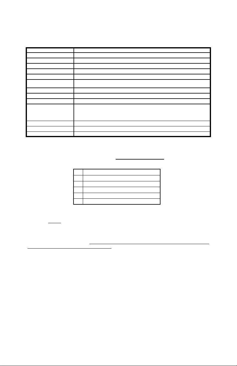
S ECIFICATIONS
UN ACKING
Inspect contents for shipping damage. If found alert carrier immediately.
Contact supplier immediately if any items are missing.
INSTALLATION
Proper installation of the unit is essential for years of safe, reliable operation. Please read all
instruction before installing the unit. Failure to follow these instructions can cause serious dam-
age to the unit or vehicle and may void warranties.
SAFETY RECAUTIONS
For the safety of the installer, vehicle operator, passengers and the community please observe
the following safety precautions. Failure to follow all safety precautions and instructions may
result in property damage, injury or death.
Qualifications - The installer must have a firm knowledge of basic electricity, vehicle electrical
systems and emergency equipment.
Mounting - The mounting bracket supplied can be installed above or below the unit. Choose a
mounting location convenient to the operator and away from any air bag deployment areas.
Inspect behind mounting area for clearance. Assure adequate ventilation to prevent overheating.
Consider wire routing and access to connections. Install mounting bracket to vehicle using 1/4"
hardware (not supplied). If mounting in a rack or console, make sure that mounting bolts do not
enter case more than 1/4".
Wiring - Use wiring capable of handling the current required. Make sure all connections are tight.
Route wiring to prevent wear, overheating and interference with air bag deployment. Install and
check all wiring before connection to vehicle battery.
Testing - Test all siren functions after installation to assure proper operation. Test vehicle opera-
tion to assure no damage to vehicle.
Keep These Instructions - Keep these instructions in the vehicle or other safe place for future
reference. Advise the vehicle operator of the location.
Sound Hazard - Sound level from siren speaker (>12 dBA @ 1 feet) may cause hearing damage.
Do not operate siren without adequate hearing protection for you and anyone in immediate vicinity.
(Ref. OSHA 191 .95 for occupational noise exposure guidelines)
Speaker Load Single 1 W 11ohm
Input Voltage 1 - 16 VDC (negative ground)
Input Current 8 AMPS (@14 VDC - single 1 W speaker)
Standby Current Less than 5mA
Output Power 1 5 WATTS RMS MAX. (15 VDC - single 1 W speaker)
Siren Frequency 7 Hz - 15 Hz (Two-Tone and Horn = 435 & 585Hz)
Tones / Cycle Rates Horn Wail Power C Yelp Phaser Two-Tone
1 9 CPS 13 CPM 1 CPM 19 CPM 15 CPS 6 CPM
High Voltage Protection 16 - 18 VDC will cause siren output to cease, resume at normal voltage
Short Circuit Current 5 AMPS (supply circuit must be capable of supplying this for 1 second)
Operating Temp. -15° F to +14 °F
Controls 3-position rocker selector switch (Yelp, Wail and Standby).
3-position momentary rocker switch (Horn and Manual/Phaser toggle).
Positive or Negative Auxiliary input.
8-position DIP switch option selector.
Connections (6-Pin Conn) (2) Power, (2) Speaker, and Auxiliary +/-.
Size 4-1/2" Wide, 1-13/16" High, 4-13/16" Deep
Weight 3 LBS.
Qty Item
1 Amplifier
1 CP4688- 6 6-Pin Terminal Block Plug
1 CP5166 Instruction Manual
1 CP5 37 Bracket, ‘U’ Dash Mount
2 CP3966 Bolts, ‘U’ Mounting Bracket