Carson HA-100-10 User manual

Carson Manufacturing Co., Inc.
5451 North Rural Street
Indianapolis, IN 46220
Phone: (888) 577-6877 Fax: (317) 254-2667
www.carson-mfg.com
HA-100-10
HORN AMPLIFIER
INSTALLATION AND OPERATING
INSTRUCTIONS
This product is legal in most states.
Please consult your state/local vehicle codes to ensure compliance with vehicle horn regulations.
Carson is a trademark of Carson Manufacturing Company, Inc.
Sound Hazard - Sound level from horn speaker (>120dBA @ 10 feet) may cause hearing damage.
Do not operate unit without adequate hearing protection for you and anyone in immediate vicinity.
(Ref. OSHA 1910.95 for occupational noise exposure guidelines)
NE
G
SP
K
SP
K
POS

Page 2 of 4 HA-100-10 14 Installation and Operating Instructions
01/27/10 CP5031A
GENERAL DESCRIPTION
The HA-100 Horn Amplifier is a premium unit designed for an 11 ohm 100 watt speaker. The unit
produces a simulated air-horn sound. This compact unit utilizes short circuit, high voltage, and
reverse polarity protection systems for maximum service life. An output indicator light is provided
for diagnostics.
SPECIFICATIONS
NOTICE
Due to continuous product improvements, we must reserve the right to change any specifications and information,
contained in this manual at any time without notice.
Carson Manufacturing Co., Inc. makes no warranty of any kind with regard to this manual, including, but not
limited to, the implied warranties of merchantability and fitness for a particular purpose.
Carson Manufacturing Co., Inc. shall not be liable for errors contained herein or for incidental or consequential
damages in connection with the furnishing, performance, or use of this manual.
See www.carson-mfg.com for latest information.
INSTALLATION
Proper installation of the unit is essential for years of safe, reliable operation. Please read all
instruction before installing the unit. Failure to follow these instructions can cause serious dam-
age to the unit or vehicle and may void warranties.
SAFETY PRECAUTIONS
For the safety of the installer, vehicle operator, passengers and the community please observe
the following safety precautions. Failure to follow all safety precautions and instructions may
result in property damage, injury or death.
Qualifications - The installer must have a firm knowledge of basic electricity, vehicle electrical
systems and emergency equipment.
Mounting - Mount the unit for easy access by the vehicle operator. DO NOT mount in air bag
deployment area. Assure clearances before drilling in vehicle.
Wiring - Use wiring capable of handling the current required. Make sure all connections are tight.
Route wiring to prevent wear, overheating and interference with air bag deployment. Install and
check all wiring before connection to vehicle battery.
Testing - Test for proper unit operation. Test vehicle operation to assure no damage to vehicle.
Keep These Instructions - Keep these instructions in the vehicle or other safe place for future
reference. Advise the vehicle operator of the location.
UNPACKING
Inspect contents for shipping damage. If found alert carrier immediately.
Contact supplier immediately if any components are missing.
Contents of box should include the following items:
Qty Item
1 Amplifier Unit (HA-100-10 14)
1 Connector, 4-P Terminal Block Plug (CP4688-04)
1 Instruction Manual (CP5031 This Manual)
Speaker Load Single 100W 11ohm
Input Voltage 9 - 16 VDC (negative ground)
Input Current 8 AMPS (14 VDC)
Output Power 105 WATTS RMS MAX. (15 VDC)
High Voltage Protection 16 - 18 VDC will cause output to cease, resume at normal
Short Circuit Current 50 AMPS (supply circuit must be capable of supplying this for 1 second)
Operating Temp. -15° F to +140°F
Size 3-5/8" Long, 4-1/4" Wide, 1-13/16" High
Weight 1 LB.
Sound Hazard - Sound level from horn speaker (>120dBA @ 10 feet) may cause hearing damage.
Do not operate unit without adequate hearing protection for you and anyone in immediate vicinity.
(Ref. OSHA 1910.95 for occupational noise exposure guidelines)

HA-100-10 14 Installation and Operating Instructions Page 3 of 4
CP5031A 01/27/10
MOUNTING
Select a location for the unit in an area such as the driver compartment firewall, under a seat, etc.
Mounting the unit in the engine compartment or in an area directly exposed to weather is not
recommended. Allow clearance for wiring. Inspect behind mounting area for clearance. Install
the terminal block plug and make all electrical connections before final mounting.
ELECTRICAL CONNECTIONS
Electrical connections to the unit are made using a removable terminal block plug located on the
side. A label on the unit identifies each terminal function. You should install the plug on the unit
before wiring. If the unit needs service the plug can be easily removed without unwiring.
The power supply of the unit must be capable of delivering peak currents up to 50 amps for ade-
quate short circuit protection and reliable operation. The unit is fused near the connector.
Attach leads by stripping 3/8", inserting into plug and clamp by tightening screw. Make sure the
screw is tight and the wire can't be pulled out.
Failure to adequately tighten the screw can result in improper operation or burning the
connector and wire.
Wire Size and Termination - The diagram shows the minimum wire size used for each connec-
tion, along with recommended lead color. If the wire is longer than 15 ft. use the next larger wire
size. Use only high quality crimp connectors for installation on the vehicle.
NOTE: Permanent disconnection of the vehicle horn is NOT recommended.
OPERATION
As soon as power is applied, the unit produces a simulated air horn sound and the output indica-
tor lights up. The output indicator is located opposite the end with connector.
4-P Terminal Block Plug
(CP4688-04)
15A Automotive
Type Fuse
Plug into unit first for
terminal identification
Plug installed
this orientation
#18G BRN
#18G BRN
#16G RED to +VDC
#16G BLK to -VDC
NEG
SP
K
SP
K
POS
Amplifier Power
Connection Examples
Assumes Power is +VDC
May be powered with
-VDC instead, just change
to -VDC and Amp NEG in
diagrams.
HORN RLY +VDC
Added
SPDT
Switch
Vehicle
Horn
+VDC
Momentary
SPST
Switch
To Amp POS
Horn
Circuit
Note:
Vehicle horn
will also sound
Vehicle
Horn
S
p
lice
To
Amp POS To Amp POS
+VDC
Added
Relay
Sound Hazard - Sound level from horn speaker (>120dBA @ 10 feet) may cause hearing damage.
Do not operate unit without adequate hearing protection for you and anyone in immediate vicinity.
(Ref. OSHA 1910.95 for occupational noise exposure guidelines)

Page 4 of 4 HA-100-10 14 Installation and Operating Instructions
01/27/10 CP5031A
SERVICE
This unit is designed to provide years of reliable service under even the worst conditions. Many
times there may appear to be a problem with the unit when the true problem is in the speaker or
improper installation. The following chart shows typical symptoms and possible causes.
A blown fuse doesn't necessarily mean that the unit is bad. If a speaker or speaker lead is
shorted the fuse will blow before the unit is damaged. Disconnect the SPK leads and replace the
fuse. If the output indicator light on the end of the unit comes on with power applied it is OK.
Check the speaker or leads for possible shorting.
PROBLEMS
PARTS and ACCESSORIES
The following parts and accessories are available from Carson Manufacturing Company, Inc.:
RETURN
If you have any questions concerning this or any other Carson product, please contact our Tech-
nical Service Department at (888) 577-6877. Many issues can be handled over the phone. We
If a product must be returned for any reason, please contact our Technical Service Department to
obtain a Returned Merchandise Authorization number (RMA#) before you ship the product to
Carson. Please write the RMA# clearly on the package near the mailing label. Be sure to provide
a return address, contact and phone number, along with a brief description of the problem.
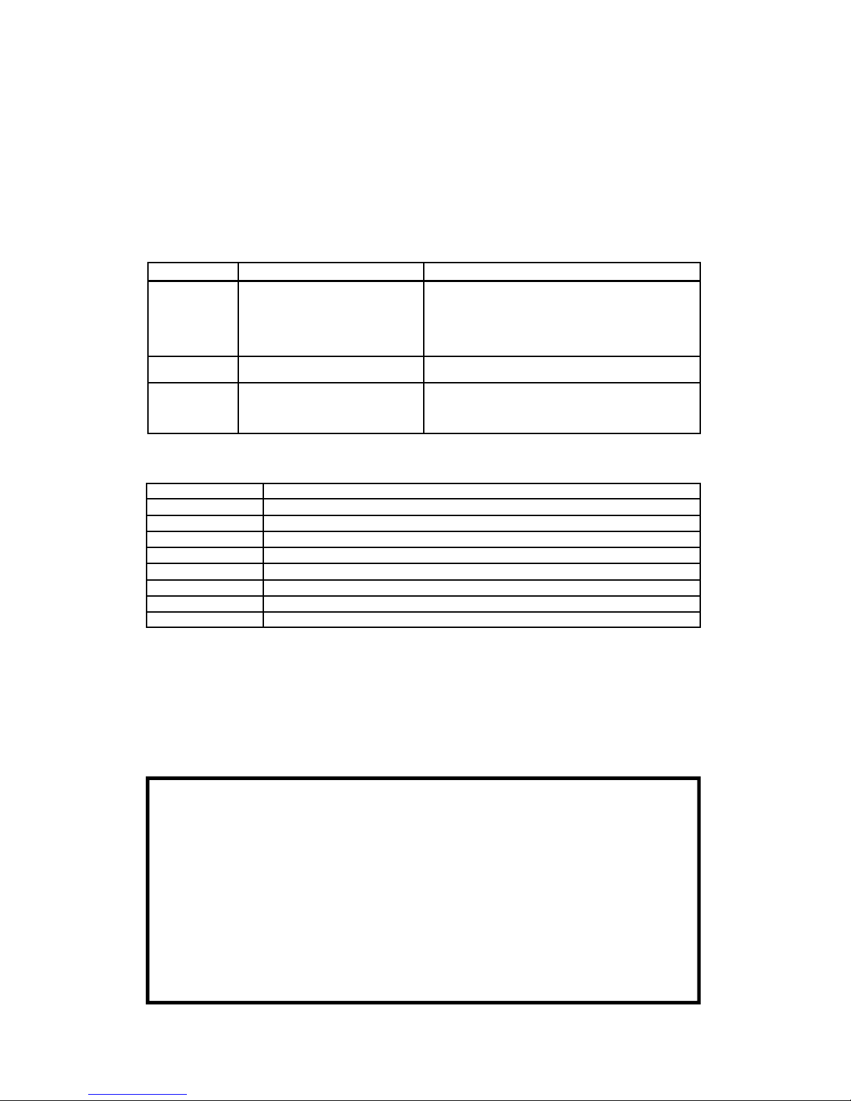
Symptom Possible Cause Check
No power or
output
Power not applied
Connector loose
Fuse blown
Loose connection at power source
High Voltage Protection
Bad speaker
Is the output indicator light coming on?
Is an external fuse or circuit breaker used?
Are the negative leads connected to a good ground?
Input voltage must be less than highest rated voltage.
Try another speaker.
Distorted sound Speaker assembly loose
Low vehicle voltage
Is the speaker bell or tip loose?
Input voltage must be greater than lowest rated voltage.
Intermittent tone High Voltage Protection
Connector loose
Bad power connection
Circuit breaker in supply connection
Is the vehicle voltage regulator working properly?
Is the connector tight on the unit?
Is there a loose connection on a power lead?
Is a circuit breaker used with at least a 50A rating?
Part Description
CP5030 Cover (not including chassis)
CP4990-150 Fuse, 15 Amp Mini Automotive
CP4998 Transistor, output (2 required)
Accessory Description * - standard accessory supplied with unit
ED1914 Cable, 4-P Lead Assembly 15FT (made w/ CP4688-04 Conn)
CP4688-04 * Connector, 4-P Terminal Block Plug
CP5031 * Manual, HA-100-10 Instruction
LIMITED WARRANTY
Carson Manufacturing Company, Inc. warrants this new product to be free from defects in material and workmanship, under normal use
and service, for a period of five (5) years from the date of delivery to the first user-purchaser.
During this warranty period the obligation of Carson Manufacturing is limited to repairing or replacing, as Carson Manufacturing may elect,
any part or parts of such product which after examination by Carson Manufacturing is determined to be defective in material and/or
workmanship.
This warranty does not cover labor charges for removal or re-installation of the product. Fuses and lamps are not covered under this
warranty.
This warranty does not extend to any unit that has been subjected to abuse, misuse, improper installation or which has not been ade-
quately maintained, nor to units which have problems related to service or modification at any facility other than the manufacturer.
THERE ARE NO OTHER WARRANTIES, EXPRESSED OR IMPLIED, INCLUDING BUT NOT LIMITED TO, ANY IMPLIED WARRANTIES
OF MERCHANTABILITY OR FITNESS FOR A PARTICULAR PURPOSE. IN NO EVENT SHALL CARSON MANUFACTURING COM-
PANY, INC. BE LIABLE FOR ANY LOSS OF PROFITS OR ANY INDIRECT OR CONSEQUENTIAL DAMAGES ARISING OUT OF ANY
SUCH DEFECT IN MATERIALS OR WORKMANSHIP.
Table of contents
Other Carson Amplifier manuals

Carson
Carson SC-1002 User manual

Carson
Carson SA-400-83 User manual

Carson
Carson SC-550-10 User manual

Carson
Carson SA-400 Classic User manual

Carson
Carson SA-400-11 User manual

Carson
Carson LCS-7-01 User manual

Carson
Carson SA-400-73 User manual

Carson
Carson SA-365-10 User manual

Carson
Carson SA-500-27 User manual

Carson
Carson HA-150-10 User manual

Carson
Carson SC-411RS-10 14 User manual

Carson
Carson SA-361-30 User manual

Carson
Carson SA-450-80 User manual

Carson
Carson SC-1002 User manual

Carson
Carson SA-430-83F User manual

Carson
Carson SA-365-20 User manual

Carson
Carson SA-500-16 14V User manual

Carson
Carson SA-400 Classic User manual

Carson
Carson SA-400-63 14V User manual

Carson
Carson SC-1002 User manual