Carson CARWHDSK User manual
Page 1 of 10
ASSEMBLY INSTRUCTIONS
NOTICE D'ASSEMBLAGE
MODEL#/N°DE MODÈLE# CARWHDS1&S2/CARBKDS1&S2
DESCRIPTION: CARSON WHITE/BLACK DESK BASE & TOP
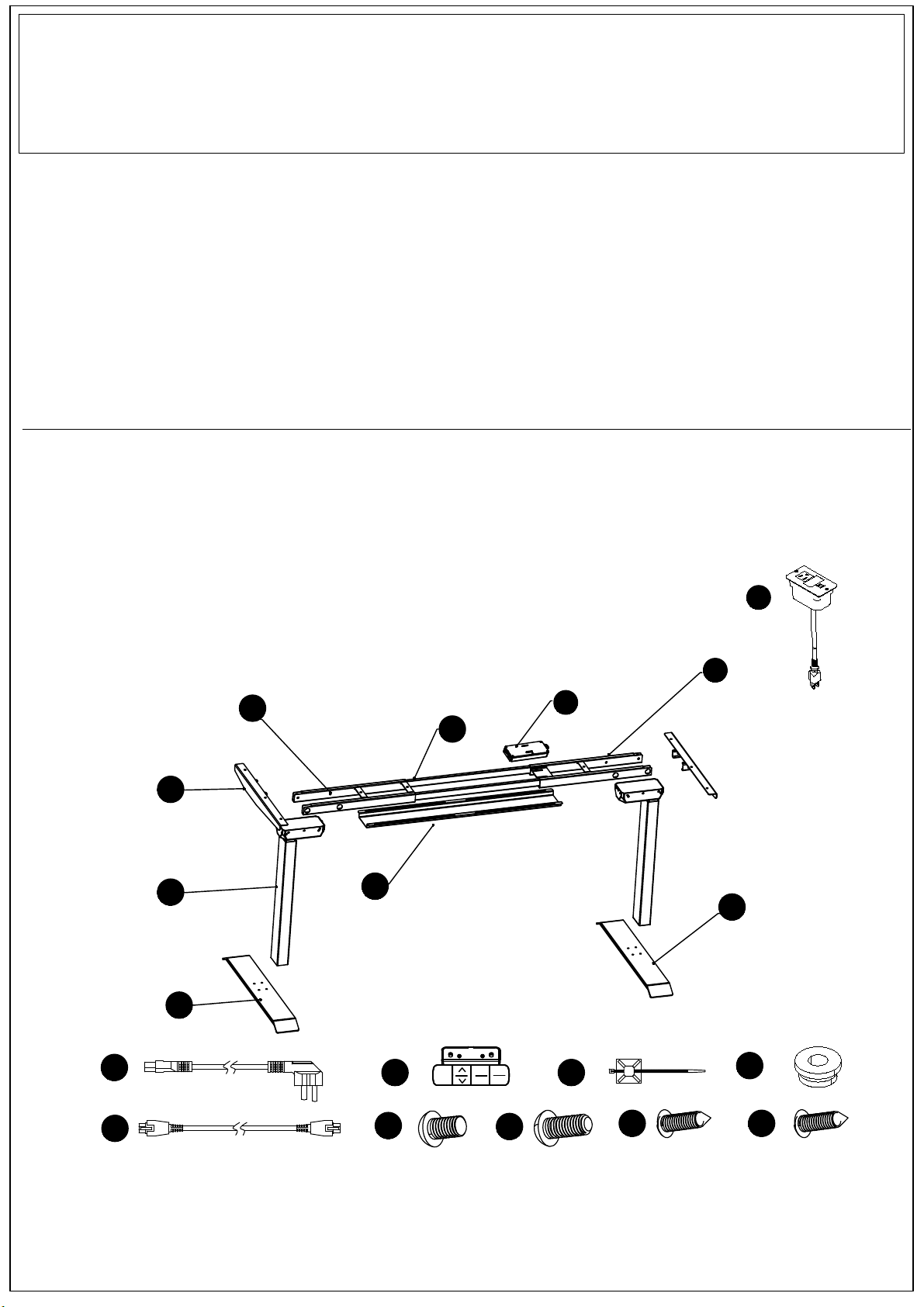
HARDWARE IDENTIFICATION / IDENTIFICATION DES PIECES MONTAGE
11
10 12
13 14 15 16
9
1
2
3
4
5
4
6
7
8
1
2
3
M
69.5
17
18
Important note/Note importante:
1. Before you begin: Lay out all parts on a clean surface to check if the tags and numbers are correct./
Avant de commencer : Disposer toutes les pièces sur une surface propre pour vérifier si les étiquettes
et les numéros sont corrects.
2. Don't screw tightly before all the screws are put into the corresponding holes./ S'assurer que toutes
les vis soient placées dans les perforations correspondantes avant de commencer à visser.
3. Please use the screws correctly, otherwise you might damage the desk panel./ Utiliser les vis
correctement, sinon vous risquez d'endommager le panneau du bureau.
4. It is recommended to install this desk by two people./ Il est fortement recommandé de mobiliser au
moins deux personnes pour le montage.
Page 2 of 10
No.
Numéro
Component name
Nom de la composante
Amount(PCS)
Quantité (PCES)
11
frame(with holes)
cadre (avec perforations)
side panel
panneau latéral
2
3
4feet
pieds
connecting pole
pôle de connexion
wire supporter
support de fil
5
6
2
2
2
2
1
1
1
1
1
10
9
7
8
9
10
11
12
N2 controller
commande N2
frame with controller(with holes)
cadre avec commande (avec perforations)
power cord
cordon d'alimentation
hand controller
commande manuelle
wire clip
pince à fil
soft rubber mat
tapis en caoutchouc souple
1
13
16
14
23
15
2
16
2
17
1
18
extension wire
Fil de rallonge
M6x10hexagon flat round head screw
vis hexagonale à tête ronde plate M6x10
M6x14 hexagon flat round head screw
vis hexagonale à tête ronde plate M6x14
ST5*16 tapping screw
vis taraudeuse ST5*16
ST4.2x16 tapping screw
vis taraudeuse ST4.2*16
charger station
station de charge
lift pole
pôle d'appui

Page 2 of 10
M6x14
hexagon flat round head screw
M6x10 hexagon flat
round head screw
M6x14 hexagon flat
round head screw
M6x14 hexagon flat
round head screw
ST4.2x16
tapping screw
3
9
2
4
5
Step 4 · Put frame at the center of desktop, extend frames to adjust width
accordingly;
Step 3 · Use four M6*14hexagon screws to fix desk leg and feet;(8pcs)
Step 1 · Take controlling box from installing shelf and put it aside. Step 2 · Use four M6*10 hexagon flat round head screws to fix frame and
standing pole;(8pcs)
· Separate installing shelf and controlling box installing shelf, take out
two central beams inside. · Use two M6*14 hexagon flat round head screws to fix side panel
and frame;(4pcs)
· Insert two connecting poles into installing shelves,make sure the
open slot of central beam is closer to desk leg(with thinner sides
upwards).
· Use M6x14 hexagon flat round head screws to tighten(put soft
cushion between desktop and frame(11pcs),use two ST4.2*16
tapping screws to fix hand controller.
Étape 1 · Retirer le boîtier de contrôle de l'étagère d'installation et le mettre
de côté.
· Démonter les pièces de l'étagère d'installation en séparant les
cadres de l'étagère et en retirant les deux poutres centrales qui sont
à l'intérieur.
Étape 2 · Utiliser quatre vis hexagonales à tête ronde plate M6x10 pour fixer
le cadre avec le pôle d'appui;(8 pces)
· Utiliser deux vis hexagonales à tête ronde plate M6x14 pour fixer
le panneau latéral avec le cadre;(4 pces)
Étape 3 · Utiliser quatre vis hexagonales à tête ronde plate M6x14 pour fixer
les pieds du bureau;(8 pces)
. Insérer deux pôles de connexion dans les étagères d'installation,
en s’assurant que la partie ouverte de la poutre centrale soit
placée proche du pied du bureau (contenant les côtés plus fins vers
le haut).
Étape 4 . Placer le cadre au centre du dessus du bureau, étendre les cadres
pour ajuster la largeur en conséquence ;
· Utiliser les vis hexagonales à tête ronde plate M6x14 pour serrer
(déposer un coussin souple entre le dessus du bureau et le
cadre)(11 pces),utiliser deux vis taraudeuses ST4.2*16 pour fixer la
commande manuelle.
vis hexagonale à tête
ronde plate M6x10
vis hexagonale à tête
ronde plate M6x14
vis hexagonale à tête ronde
plate M6x14
vis hexagonale à tête
ronde plate M6x14
vis taraudeuse
ST4.2*16
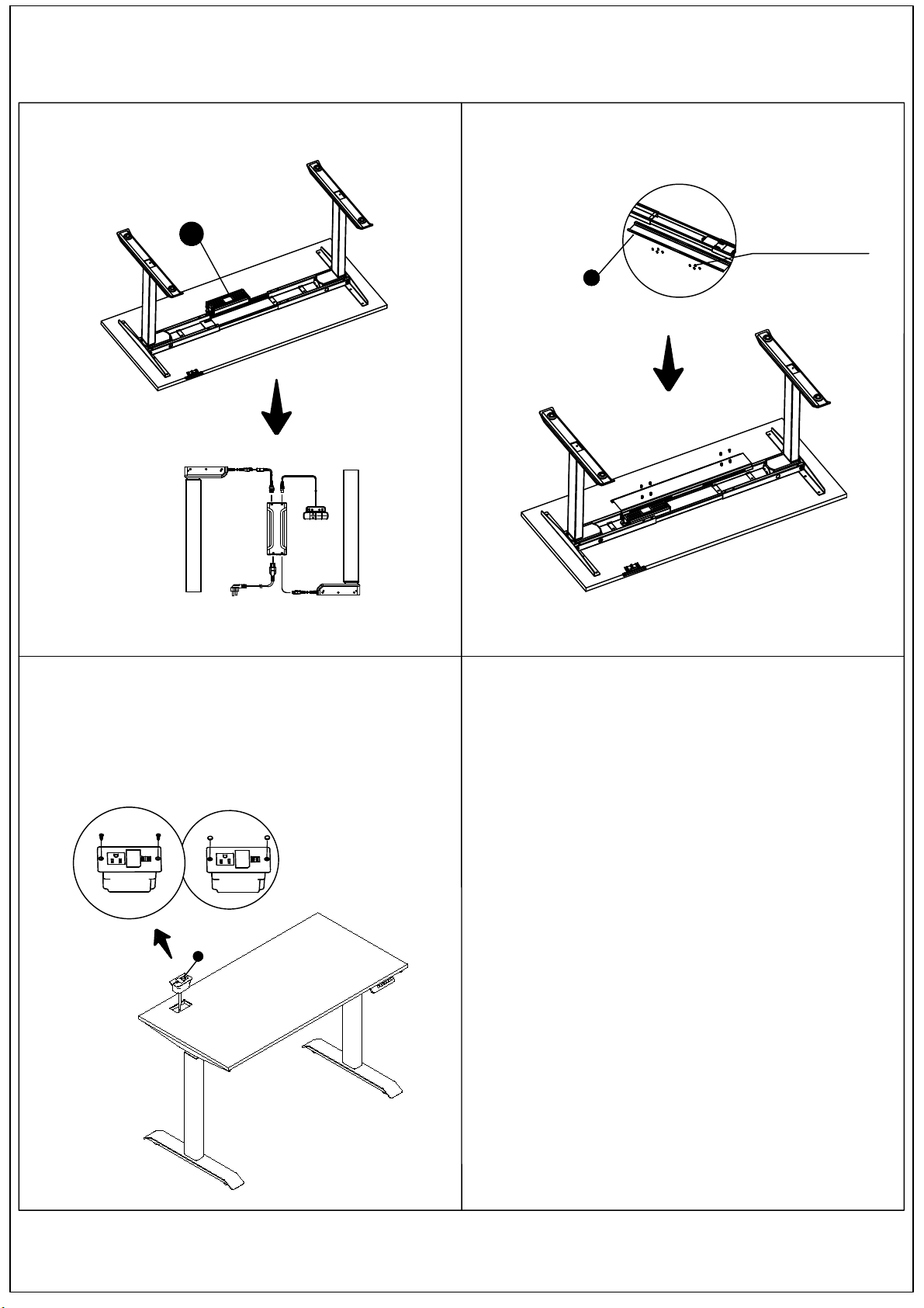
Step 6
Page 4 of 10
M6x10 hexagon flat
round head screw
7
1
2
3
M
69.5
8
18
· Use eight M6*10 hexagon flat round screws to lock wire supporter
and frame;
Step 5 · Insert controller into frames and connect accessories, fix them with
wire clips;
Step 7 · Put the charger station in the front left slot of the table top;
Use two ST3.5*12 Screws to fix charger station;
Put the two screw plugs into the screw hole position.
Étape 7. Placer la station de chargement devant le canal à fil gauche du plateau
de la table ;
Utiliser deux vis ST3.5*12 pour fixer la station de chargement ;
Placer les deux bouchons à vis à l'endroit des perforations.
Étape 5 . Insérer la commande dans les cadres et connecter les accessoires,
les attacher ensuite avec les pinces à fil. Étape 6 · Utiliser huit vis hexagonales à tête ronde plate M6x10 pour verrouiller
le support de fil avec le cadre;
vis hexagonale à tête
ronde plate M6x10

Please make sure there is no obstacle during the operation,and there
is a gap between desk and wall.And all wires are long enough to allow
the up-down of desk.
Note
Please set up as 1 the most comfortable height when you sit down,
and set up as 2 the most comfortable height when you stand up. For
the other two heights, you can choose whatever you like.
Advice
When there is something wrong with controller
reported,the digital tube shows E07-E09,Even if it has
access to power after a power cut-off, it will still give
an error notice no matter what button you press.
Reset abnormality protection
Operation
After pressing for 5s and digital tube shows
RST,release the button and press the down
button, reset will be activated.
Set up upper limit position
Press M button,the digital tube shows“S-”,then release
the button.Press the up button,the digital tube will flash
once,release the button.Press M button again for 2s,
the digital tube shows“999”.The upper limit position
has been set.
Press M button,the digital tube shows“S-”,release the
button.Press the down button. The digital tube will flash once.
Release the button.Press down M button again for 2s,the digital
tube shows“000”.The lower limit position has been set.
Set up lower limit position
1
2
3
M
69.5
3 level
default heights setting
up/down
desk height
1
2
3
M
69.5
long press for 5S
1
2
3
M
69.5
long press for 2S
1
2
3
M
69.5
long press for 2S
Page 5 of 10
This manual suits for next models
5
Other Carson Indoor Furnishing manuals


Popular Indoor Furnishing manuals by other brands

Regency
Regency LWMS3015 Assembly instructions

Furniture of America
Furniture of America CM7751C Assembly instructions

Safavieh Furniture
Safavieh Furniture Estella CNS5731 manual

PLACES OF STYLE
PLACES OF STYLE Ovalfuss Assembly instruction

Trasman
Trasman 1138 Bo1 Assembly manual

Costway
Costway JV10856 manual


