Carter CT10 Manual

CT08/CT10 MINI CRAWLER EXCAVATOR
OPERATION & MAINTENANCE MANUAL
SHAN DONG CARTER HEAVY INDUSTRY MACHINERY CO., LTD
Add: Economic Development Zone, Linshu County, Shandong Province, 276715, China
Tel: +86-539-7190561
1

Preface
Chapter I Usage Features and Performance Parameters of Carter 0.8T/1.0T Excavators
Section I Usage and features
Section II Main performance parameters
Chapter II Basic Structures and Work principle of Carter 0.8T/1.0T Excavators
Section I Overview
Section II Work principle
Section III Basic structure of mechanical system
Section IV Basic structure of hydraulic system
Chapter III Service Technologies of Carter 0.8T/1.0T Excavators
Section I Basic construction knowledge
Section II Preparation for work
Section III Operational essentials
Section IV Operational precautions
Chapter ⅣMaintenance of Carter 0.8T/1.0T Excavators
Section I Daily inspection
Section II Periods of overhaul, medium and minor repair
Chapter V Troubleshooting of Carter 0.8T/1.0T Excavator
Section I General
Section II Troubleshooting of mechanical system
Section III Troubleshooting of hydraulic system
Section IV Troubleshooting of electrical control system
Section V Troubleshooting of engine
Section VI Other
2

Chapter I Usage Features and Performance Parameters of Carter 0.8T/1.0T
Excavators
Section I Usage and features
Carter 0.8T/1.0T Excavators are provided with excavating, crushing, ditch cleaning, drilling and bulldozing,
with their attachments quick hitched and thus its utilization up greatly. In addition, they are easy to operate and
transport and flexible to work at narrow site.
Carter 0.8T/1.0T Excavators, hydraulic type with single bucket
This type of excavators are mainly applied to: farming, landscaping, ditching and fertilization in garden, vegetable
greenhouse, agricultural transformation, indoor demolition, small earthwork, civil engineering, road recovery,
basement and indoor construction, concrete breaking, burying of cable, laying of water supply line, garden
cultivation, desilting and others.
The excavator are equipped diesel engines, domestic main pumps and rotary motors, traveling motor, featuring
comprehensive guarantee, durability and flexibility.
Excavators are able to equipped with multiple work equipments, such as quick hitch, log grab, ripper, leveling
bucket, auger and narrow bucket, as well as optional roof, radiator and others, so as to meet your needing.
3

Quick hitch Narrow bucket
Log grab Mechanical thumb
Auger Ripper Rake
4

Section II Main performance parameters
5

Appearance parameters
Overall dimensions
CT08
CT10
Unit: mm
A Wheel track
900
900
B Overall length of track
1233
1233
C Ground clearance of platform
385
385
D Ground clearance of platform tail
800
815
E Chassis width
840
840
F Crawler width
180
180
H Crawler height
324
324
I Transportation length
2876
2976
J Overall height
(
Driving shed top
)
1495
1495
Deflection angle left °/ right °
/
50°/70°
Working parameters
Work range
CT08
CT10
Unit: mm
A Max. digging radius on ground
2992
3125
B Max. digging depth
1787
1520
C Max. digging height
2550
2585
D Max. unloading height
1687
1715
E Max. vertical digging depth
1626
/
F Min. swing radius
1483
1595
G Max. lifting height of dozer blade
340
340
H Max. digging depth of dozer blade
260
260
Performance parameters
Weight of complete machine kg
850
920
Standard bucket capacity m³
0.022
0.022
Rated power kw
7.0
7.0
6

Chapter II Basic Structures and Work Principle of Carter 0.8T/1.0T Excavators
Section I Overview on Carter 0.8T/1.0T excavators
Carter 0.8T/1.0T excavator is composed of power train, work equipment, swing mechanism, control mechanism,
drive system, traveling mechanism and auxiliary equipment, as shown in fig. 1-1. Mounted on the rotary table are
the regular full-swing type hydraulic excavators, main components of drive system, swing mechanism and
auxiliary devices, which are referred to as upper rotary. Therefore, a Carter 0.8T/1.0T excavator is divided into
work equipment, upper rotary and traveling mechanism.
7

Section II Work principle of excavators
Diesel engine changes the chemical energy of diesel into mechanical energy that is then altered with hydraulic
gear pump to hydraulic energy that is distributed to each actuating element (such as hydraulic cylinder, swing
motor and traveling motor). After that, each actuating element transform the hydraulic energy back to mechanical
energy, driving the work equipment and running the complete machine.
Central
slewing joint
Movement and power transmission route of excavator shown below:
1. Traveling power route: diesel engine —— coupler —— hydraulic pump (mechanical energy changed to
hydraulic energy) —— distributor valve —— central swing joint —— traveling motor (hydraulic energy
changed to mechanical energy)—— sprocket —— rubber crawler—— starting of traveling
2. Swing power route: diesel engine —— coupler —— hydraulic pump (mechanical energy changed to
hydraulic energy) —— distributor valve—— swing motor (hydraulic energy changed to mechanical energy)
—— slewing bearing —— realizing of wing
3. Boom power route: diesel engine —— coupler —— hydraulic pump (mechanical energy changed to
hydraulic energy) —— distributor valve —— boom cylinder (hydraulic energy changed to mechanical
energy)——boom movement
4. Arm power route: diesel engine —— coupler —— hydraulic pump (mechanical energy changed to hydraulic
energy) —— distributor valve —— arm cylinder (hydraulic energy changed to mechanical energy) —— arm
movement
5. Bucket power route: diesel engine ——coupler —— hydraulic pump (mechanical energy changed to
hydraulic energy) —— distributor valve —— bucket cylinder (hydraulic energy changed to mechanical
energy) —— bucket movement
8

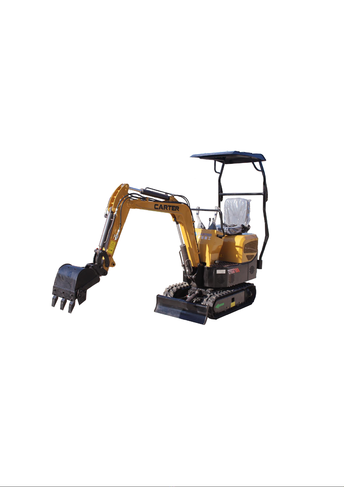
Section III Basic structure of Carter 0.8T/1.0T excavators mechanical system
1 Power system
Carter 0.8T/1.0T excavator is equipped with single-cylinder air-cooling diesel engine.
2 Drive system
Carter 0.8T/1.0T excavator's drive system could transfer the output power from diesel engine through the
hydraulic system to work equipment, swing mechanism and traveling mechanism.
3 Swing mechanism
Swing mechanism could turn the work equipment and upper rotary leftwards and rightwards, so as to do the
excavating and the unloading. Carter 0.8T/1.0T excavator’s swing mechanism has to fix the rotary table onto
frame and has it swing flexibly, without any inclining risk. Therefore, Carter 0.8T/1.0T excavator is equipped with
a slewing support (supports) and a slewing drive (power of turntable slewing), which are called by a joint name as
swing mechanism.
3.1 Slewing support
Carter 0.8T/1.0T excavator has its rotary table supported with a rolling bearing, realizing the swinging of
upper rotary.
3.2 Rotary drive
Carter 0.8T/1.0T excavator adopts the direct drive type. Namely, the output shaft of low-speed high-torque
hydraulic motor is mounted with a driving pinion which meshes with the slewing gear ring.
4 Traveling mechanism
Traveling mechanism supports the complete weight of excavator and drives it to run.
Carter 0.8T/1.0T excavator has the crawler traveling mechanism similar to other crawlers, with one hydraulic
motor driving one track. This excavator adopts low-speed high-torque motor. When two hydraulic motors run in
the same direction, this machine goes straightly forward; when one motor is supplied with oil and the other is
braked, excavator steers around the braked track; when two motors runs reversely, excavator rotates in situ.
Each part of traveling mechanism is mounted on integral traveling frame. The pressure oil from hydraulic pump
goes through the multi-way directional valve and the central swing joint into the hydraulic traveling motor that
changes the pressure energy into output torque that then goes to sprocket, driving excavator to run.
Carter 0.8T/1.0T excavator’s sprockets are of integral castings and able to correctly engage with track, featuring
balance drive. Sprockets located at rear part of excavator, shortening the tensioner part and relieving the track
abrasion, wear and power consumption. Each track is equipped with a tensioner, adjusting the track tension and
reducing the track vibration noise, abrasion, wear and power loss.
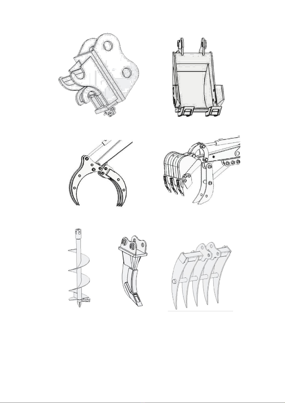
5 Work equipment
The hydraulic excavator could have multiple work equipment, up to dozens of varieties, with backhoe and ripper
most popular.
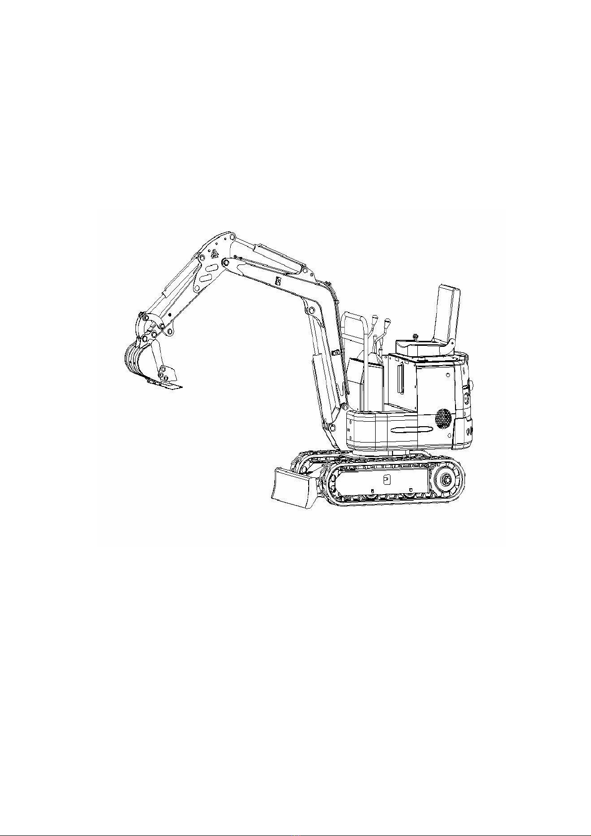
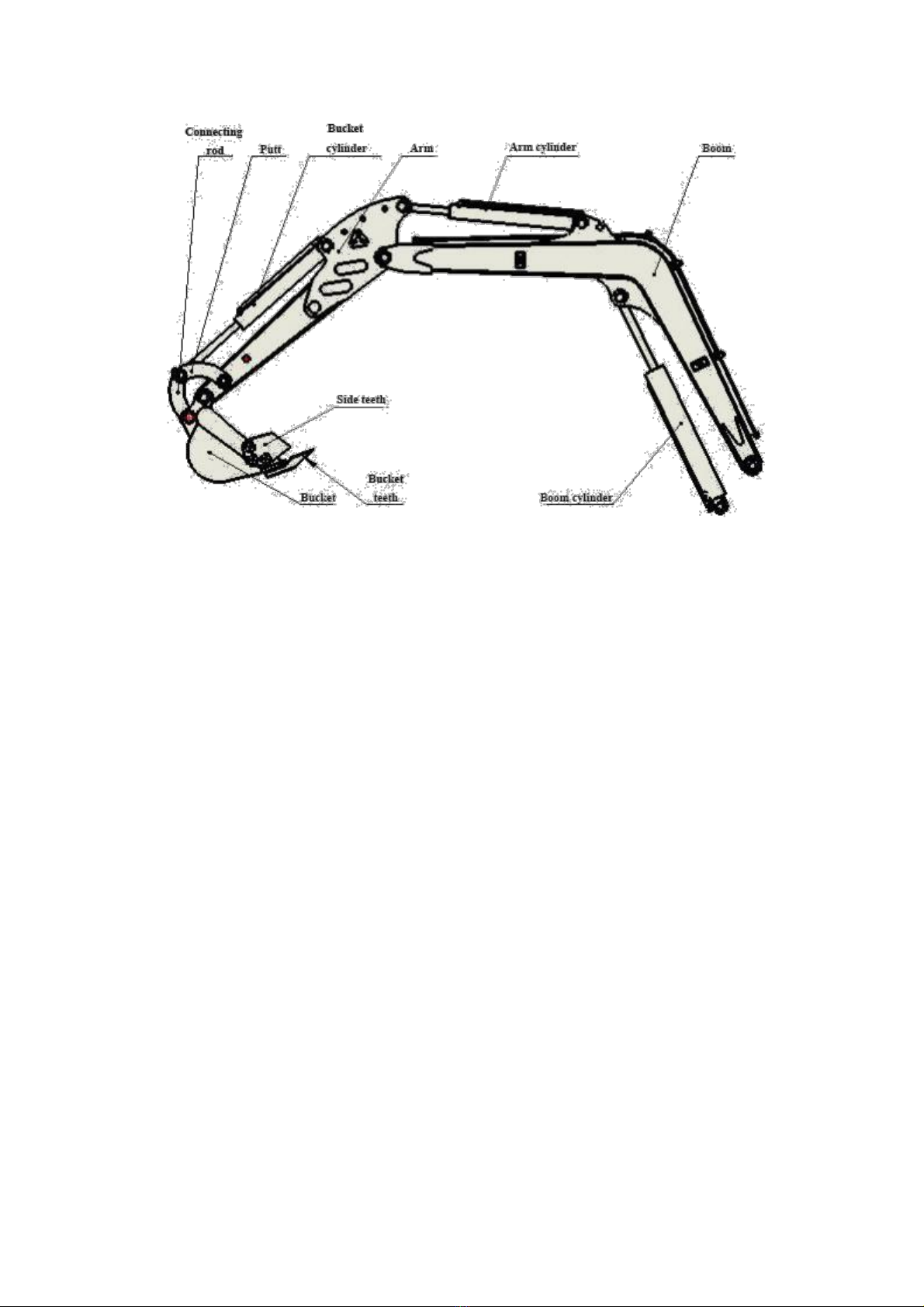
Carter 0.8T/1.0T excavator has the boom, arm and bucket articulated with each other, as shown in figure and
swing around their articulated points respectively with aid of the hydraulic cylinder, finishing the excavating,
lifting and unloading.
5.1 Boom
As the main component of backhoe work equipment, the integrated skewed boom is adopted on Carter 0.8T/1.0T
excavator.
Being of the most popular type at present, skewed boom could allow excavator to dip deeper and to lower the
unloading depth, satisfying the backhoe requirements.
9

5.2 Bucket
5.2.1 Basic requirements
1) The longitudinal profile of bucket meets the law of motion of various materials inside of bucket,
facilitating the material flow and minimizing the loading resistance and thus fulfilling the bucket.
2) Bucket teeth are mounted to increase the linear specific pressure of bucket onto material, with unit
cutting resistance relatively low and easing to cut in and break soil. In addition, the teeth are
resistant to wear and easy to replace.
3) The load is easy to get off, shortening the unloading time and increasing the effective capacity of
bucket.
5.2.2 Structure
Bucket shape and size for backhoe are highly related to work objects. In order to meet various excavation,
one excavator could be equipped with multiple types of buckets, with backhoe most popular. Bucket
teeth could be mounted with rubber pins and bolts
Connection between bucket and hydraulic cylinder is of linkage mechanism, with bucket directly
articulated with hydraulic cylinder, which drops the rotation angle of bucket but enables the work torque
to change greatly.
10

11

Hydraulic system structure of Carter 0.8T/1.0T excavators
I. Rotary motor
II. Main pump
12

Ⅲ.Traveling motor
Disc Valve Motors---6000 series -005 and -006
Drive, Main
Geroler
Screw, Cap
Screw, Cap
Displacement
Item No.5--Part No
Item No.6--Part No
Item No.6--Part No
Item No.6--Part No
Cm
3
/r(in
3
/r)
/Length
/Width
/Length
/Length
Part No
mm(inch)
Part No
mm(inch)
Part No
mm(inch)
Part No
mm(inch)
310(19.0)
21373-003
118.1(4.65)
8507-003
34.6(1.36)
14409-003
138.4(5.45)
14409-007
172.4(6.79)
13

Seal package
Code
Name (reference dimensions mm)
Quantity
1
Dust cover (OD 50.9)
1
2
Copper sheet (OD 60.45)
1
3
Seal ring of output shaft (OD 63.56)
1
4
O-ring (ID92.87
,
Shore hardness70)
1
5
End seal ring (ID 45.72)
1
6
O-ring (ID 6.07)
2
7
O-ring (ID 94.97)
2
8
O-ring (ID 11.2)
1
9
Front-type seal ring (ID 62.23)
1
10
Front-type seal ring (ID 35.82)
1
11
O-ring (ID 92.33
,
Shore hardness 90)
1
14

Section IV Schematics of main valve
Reserved
rotating
Arm
Traveling
Front shovel
Traveling
Boom
Bucket
15

Section V. Electrical system diagram
16

Chapter III Service Technologies of Carter 0.8T/1.0T Excavators
Being of high temperature and pressure, the Carter 0.8T/1.0T excavator could have the hydraulic oil temperature
as high as 85℃, the engine silencer temperature as high as 700℃and pressure as high as 16-18MPa. Therefore,
the operators should be specially trained to obtain the proper certificates and to be familiar with the contents in this
manual before the operations. In addition, maintenance and repair of excavator should be strictly in line with
regulations to avoid any accident.
Section I Basic construction knowledge
There are four basic movements: bucket rotation, arm stretching / backing, boom lifting / lowering and turntable
swinging.
In general, pulling/pushing of hydraulic cylinder and rotation of hydraulic motor is controlled with three-way axial
slide valve through the oil-flow direction and the work speed is controlled by operator or auxiliary devices
according to the quantitative system and the valve openness.
1.1 Basic requirements on control system
Basic requirements on control system include:
1) Control system should be centralized in the driving area of upper rotary and satisfy the man-machine
requirements. For example, controllers and driver seat should be designed according to 160-180 cm for
males and 150-170 cm for females.
2) Startup and stop should be steady, with its speed and strength in control. At the same time, the combine
actions should be also in control.
3) Easy, handy and visual operations In general, the operational force on handle does not exceed 40~60 N
and handle travel does not exceed 17cm.
4) Control mechanism should minimize the deformation of its lever, as well as the inside clearance and the
idle travel.
5) Ensure the operational performance does not change in -40~50℃.
Section II Preparation for work
1. Inspection before startup
In order to prolong its service span, check the following before startup:
①. Check if there is dirt around or below machine, bolts loosened, any oil leaked and if any part damaged or
worn.
②.Check if all switches, lamps and fuse box could work normally.
③. Check if the work equipment and hydraulic parts could work normally.
④.Check if all engine oil levels and fuel level are proper.
The above should be checked normal; otherwise engine cannot be started up until they are checked normal after
troubleshooting.
2. Maintenance before startup
Before startup each shift, it is needed to grease the work equipment and the slewing bearing.
3. Preheating of machine on cold days
If it is cold, engine is difficult to start up, fuel may be frozen and hydraulic oil may increase its viscosity.
Therefore, selection of fuel should be dependent on environment temperature.
17

When hydraulic oil is less than 25℃, it is needed to preheat the machine before any work; otherwise
machine may not respond or react very quickly, leading to severe accident.
Therefore it is needed to preheat machine if it is cold:
①. Adjust the manual accelerator to have engine run at medium speed, and then slowly move bucket forth and
back for 5min.
Caution: do not operate other actuators than the bucket.
②. Adjust the manual accelerator to have engine run at high speed, and then move the boom, the arm and the
bucket for 5-10min.
Caution: operations are merely limited on boom, arm and bucket, instead of any slewing or traveling.
③. Each complete action of excavator should be carried out for a few times, completing the preheating and ready
to work.
Section III Operational essentials
1. Traveling
Use the traveling handles.
(1) Straight
Forwards or backward move the handle, running the machine forwards or backwards.
(2) Steering
A. Left turn in situ: backward shift the left handle and meanwhile forward push the right handle.
b. Right turn in situ: backward shift right handle and meanwhile forward push the left handle.
c. Left turn with left track as axis: forward move the right handle
d. Right turn with right track as axis: forward move the left handle
2. Excavation
2.1 The excavator slewing and the work equipment are respectively controlled with two handles, with positions
shown below:
18
Left travel
Right travel

2.2 Basic excavation
2.2.1 Before excavation, the arm cylinder should have angle with the arm as 90°, bucket with ground to be
excavated as 30°. Only in such case, can each cylinder have the max. excavating force. It is suitable for
relatively hard soil, so as to decrease the excavating resistance.
2.2.2 To excavate any soft soil, bucket should be angled with the soil to be 60°, increasing the work
efficiency.
2.3 Lower excavation
Keep the angle between bucket base and the bevel at 30°, and retract the arm to start work.
2.4 Upper excavation
Keep the bucket blade vertical to the ground, and retract the arm to start work.
2.5 Ditching is carried out in 7 steps, as shown in figure.
19

Section IV Operational Precautions
Prohibitions and precautions for hydraulic excavators
1. Avoid the landsliding and the stone falling.
2. Avoid any striking of work equipment.
3. Avoid the bucket from colliding with other vehicle body, the loaded bucket crossing over other vehicle cab or
persons.
4. Avoid the excavator from sinking into soft ground or wetland.
5. In traveling, avoid any large obstacles such as large stone.
6. It is prohibited to work with water depth exceeding the allowable limit.
7. While unloaded or loaded, the large stones should be handled carefully not to fall down.
8. On cold days, park the machine on solid ground to avoid the track being frozen. Remove any scrap away
from track and its frame. If track is iced onto ground, use boom to lift track and carefully move the machine,
so as not to damage the sprocket and the track.
9. Before movement of machine, make sure the traveling direction is consistent with its handle. When traveling
motor is at rear part, forward push the traveling handle, to drive machine forwards.
10. For long - distance traveling, please rest for 5min every running for 20min, so as not to damage the traveling
motor.
11. Never try to cross over a slope of more than 15 degree, so as to avoid the machine from overturning.
12. Avoid any accidents occurring during machine reversing or slewing.
13. In work, do not completely dig the soil out of bottom of machine.
14. Avoid any collapse: never run on high dam or slope, which otherwise may have the machine collapsed or
sliding away, leading to severe accident.
15. Be careful of underground facilities: unexpected cutoff the underground cables or gas pipe may lead to
explosion, fire or even personal casualty.
16. Be careful of overhead facilities such as bridge: if work equipment or other parts collides with over-bridge or
others, it may result in personal injury; care must be taken to prevent the boom or the arm from colliding with
any elevated item.
17. Keep safe distance from overhead power line: in work around power line, do not have any part of machine or
any load move to 3m timed by 2 of away from the power insulation. Verify and abide by the local related
laws and rules. Wetland may have the range of electric shock enlarged. Therefore, the irrelative should be
kept away from work area.
20
This manual suits for next models
1
Table of contents
Other Carter Compact Excavator manuals